EP0359976B1 - Automatische Heizvorrichtung mit Gewichtsmesswertgeber - Google Patents
Automatische Heizvorrichtung mit Gewichtsmesswertgeber Download PDFInfo
- Publication number
- EP0359976B1 EP0359976B1 EP89114758A EP89114758A EP0359976B1 EP 0359976 B1 EP0359976 B1 EP 0359976B1 EP 89114758 A EP89114758 A EP 89114758A EP 89114758 A EP89114758 A EP 89114758A EP 0359976 B1 EP0359976 B1 EP 0359976B1
- Authority
- EP
- European Patent Office
- Prior art keywords
- weight
- heating
- detection
- electrodes
- capacitance
- Prior art date
- Legal status (The legal status is an assumption and is not a legal conclusion. Google has not performed a legal analysis and makes no representation as to the accuracy of the status listed.)
- Expired - Lifetime
Links
Images



Classifications
-
- F—MECHANICAL ENGINEERING; LIGHTING; HEATING; WEAPONS; BLASTING
- F24—HEATING; RANGES; VENTILATING
- F24C—DOMESTIC STOVES OR RANGES ; DETAILS OF DOMESTIC STOVES OR RANGES, OF GENERAL APPLICATION
- F24C7/00—Stoves or ranges heated by electric energy
- F24C7/08—Arrangement or mounting of control or safety devices
-
- H—ELECTRICITY
- H05—ELECTRIC TECHNIQUES NOT OTHERWISE PROVIDED FOR
- H05B—ELECTRIC HEATING; ELECTRIC LIGHT SOURCES NOT OTHERWISE PROVIDED FOR; CIRCUIT ARRANGEMENTS FOR ELECTRIC LIGHT SOURCES, IN GENERAL
- H05B6/00—Heating by electric, magnetic or electromagnetic fields
- H05B6/64—Heating using microwaves
- H05B6/6408—Supports or covers specially adapted for use in microwave heating apparatus
- H05B6/6411—Supports or covers specially adapted for use in microwave heating apparatus the supports being rotated
-
- H—ELECTRICITY
- H05—ELECTRIC TECHNIQUES NOT OTHERWISE PROVIDED FOR
- H05B—ELECTRIC HEATING; ELECTRIC LIGHT SOURCES NOT OTHERWISE PROVIDED FOR; CIRCUIT ARRANGEMENTS FOR ELECTRIC LIGHT SOURCES, IN GENERAL
- H05B6/00—Heating by electric, magnetic or electromagnetic fields
- H05B6/64—Heating using microwaves
- H05B6/6447—Method of operation or details of the microwave heating apparatus related to the use of detectors or sensors
- H05B6/6464—Method of operation or details of the microwave heating apparatus related to the use of detectors or sensors using weight sensors
Definitions
- the present invention relates generally to automatic heating appliances, and more particularly to an appliance for automatically controlling heating to a cooking object on the basis of variation of the weight of the object to be heated.
- heating appliances with a plurality of different sensors which automatically controlling the time period of heating of an object in accordance with signals from the plurality of sensors such as humidity sensor, gas sensor and weight sensor.
- the plurality of sensors allows automatization of a wide range of cooking category.
- the humidity sensor and gas sensor detect gases and vapors generated from the cooked object such as food and the results of the detection is used for controlling the termination of the heating of the cooked object.
- the gases and vapors developed from the frozen foods are extremely few and generally the gas sensor and humidity sensor do not have sensitivities sufficient to detect them.
- a weight sensor is employed for the control of the termination of the heating, because the thawing time can be calculated by detection of the quantity of the frozen food. That is, the relative permittivity of ice is constant and the heating time period depends on only the quantity of the frozen food regardless of kinds of cooked objects. Accordingly, various sensors should be required for desirable automatization of cooking. However, provision of a plurality of sensors results in the appliance with a complex arrangement and a complex control system, thereby causing increase in the manufacturing cost.
- an automatic heating appliance comprising the features of claim 1.
- said weight detection means is composed of an electric capacitance type pressure sensor which includes a pair of flat plate type detection electrodes facing each other to be spaced by a predetermined distance from each other and a pair of flat plate type reference electrodes facing each other to be spaced by a predetermined distance from each other and respectively provided around said pair of detection electrodes.
- Said control means is responsive to the electric capacitance due to the detection electrodes and the electrical capacitance due to the reference electrodes to calculate the weight of said object on the basis of both the sensed capacitances.
- an automatic heating appliance having therein a heating chamber for housing an object to be heated, comprising: heating means provided on or in said heating chamber for heating said object placed in said heating chamber; table means provided in said heating chamber for keeping thereon said object during heating; weight detection means for obtaining first weight data in response to said object being placed on said table means; temperature compensation means for obtaining a second weight data in response to said object being placed on said table means, said temperature compensation means substantially having the same temperature characteristic as said weight detection means; and control means coupled to said weight detection means and said temperature compensation means so as to remove an error component due to variation of the characteristic of said weight detection means by variation of temperature in accordance with the result of comparison between said first weight data obtained by said weight detection means and said second weight data obtained by said temperature compensation means so as to determine a weight of only said object, said control means controlling the heating of said object in accordance with variation of the determined object weight.
- said weight detection means is composed of an electric capacitance type pressure sensor which includes a pair of flat plate type detection electrodes facing each other to be spaced by a predetermined distance from each other
- said temperature compensation means is composed of an electric capacitance type pressure sensor which includes a pair of flat plate type reference electrodes facing each other to be spaced by a predetermined distance from each other, said temperature compensation means being disposed near said weight detection means.
- said control means is responsive to the electric capacitance due to the detection electrode and the electric capacitance due to the reference electrode to calculate the weight of said object on the basis of both the sensed capacitances.
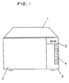
- the automatic heating appliance of this embodiment has a housing 1 equipped with an openable and closable door 2 at its front face, the housing 1 being further provided with an operating panel 3 in the vicinity of the door 2.
- the keyboard 4 On the operating panel 3 are disposed a keyboard 4 and an indication section 5, the keyboard 4 having various instruction keys such as a thawing key for giving an instruction of automatically thawing a frozen object and a heating key for providing an instruction of automatically heating an object to be heated up to a predetermined temperature.
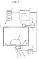
- Fig. 2 is a block diagram showing an system arrangement of the automatic heating appliance of this embodiment. Illustrated at numeral 6 is a control section which is responsive to various instructions inputted through the various operating keys of the keyboard 4 and gives indications corresponding to the instruction on the indication section 5.
- the appliance has therein a heating chamber 7 where a rotatable turntable 8 is disposed to place thereon an object 9 such as a food to be heated or cooked.
- a heating means 10 such as a magnetron which is operable in response to an electric power supply from a driver 11 under control of the control section 6.
- the turntable 8 has a rotating shaft which is coupled to a drive shaft of a drive source 12, disposed at the outside of the heating chamber 7, to as to be rotatable during heating by the magnetron 10 to prevent uneven heating of the object 9 to be heated.
- the drive shaft of drive source 12 is arranged to be movable in the directions (thrust direction) of the axis of the rotating shaft of the turntable 8 and, at its lower end portion, mechanically engaged with a weight-detecting means 15.
- a temperature compensation means 16 is disposed in the vicinity of the weight-detecting means 15.
- the weight-detecting means 15 and the temperature compensation means 16 are electrically coupled through a detection circuit 17 to the control section 6.
- the weight-detecting means may be of any one of various types weight sensors or detecting-devices such as strain gauge, electrical capacitance type pressure sensor and displacement sensor.
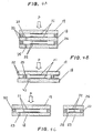
- Figs. 3A and 3B show an example of electrical capacitance type weight sensors where the weight detecting means 15 and the temperature compensation means 16 are constructed as one-piece device.
- the electrical capacitance type weight sensor 15 comprises a base plate 18 and a diaphragm which are constructed of an insulating flat plate made of an alumina, for example, and which are vertically spaced by a predetermined distance d from each other by means of a circular, or cylindrical, sealing member 20 so as to form therein a cylindrical space.
- the base plate 18 and the diaphragm 19 respectively have detection electrodes 21 which act as the weight-detection means 15 and which are disposed on substantial center portions of the inner surfaces thereof so as to face each other in the cylindrical space.
- a reference electrode 22 which acts as the temperature compensation means 16.
- the diaphragm 19 In response to application of a load P onto the diaphragm 19, the diaphragm 19 is bent as illustrated in Fig. 3A whereby the electrical capacitance Cw developed between the detection electrodes 21 varies.
- the reference electrode 22 provided around the detection electrode 21 of the diaphragm 19 is not virtually bent thereby because it is positioned near the sealing member 20 so that the electrical capacitance Cr developed between the reference electrodes 22 is substantially kept as it is.
- the reference electrodes 22 are made of the same material as the detection electrodes 21 and are respectively disposed near the detection electrodes 21, and therefore the temperature characteristics of both the detection electrode 21 and the reference electrode 22 are substantially equal to each other. While the electrical capacitance due to the detection electrodes 21 depends upon both the the load variation and the temperature, the electrical capacitance due to the reference electrodes 22 substantially depends on only the temperature variation. Accordingly, by subtracting the variation of the electrical capacitance due to the reference electrodes 22 from the variation of the electrical capacitance due to the detection electrodes 21, it is possible to attain the variation of the electrical capacitance corresponding to only the weight (load) variation of the object 9 placed on the turntable 8. In Fig.
- numeral 23 is a through-hole formed in the base plate 18, whereby the air within the cylindrical space are communicated with the outside air so as to prevent expansion and contraction of the air therewithin due to variation of the atmosphere temperature which adversely affects the temperature characteristic of the weight-detecting means.
- Figs. 4A through 4C show other weight sensors
- Figs. 4A and AB illustrating weight sensors integrally including both the weight-detecting means 15 and the temperature compensation means 16
- Fig. 4C illustrating a weight sensor in which the weight-detecting means 15 and the temperature compensation means are separated from each other but the temperature compensation means 16 is positioned near the weight-detecting means 15.
- the weight sensor is of the double layer type that a diaphragm 19 and two base plates 18 and 24 are arranged vertically so as to form two spaces therebetween by means of two sealing members 20.
- Detection electrodes 21 are respectively placed on the lower surface of the diaphragm 19 and the upper surface of the base plate 18 so as to be disposed in the upper space between the diaphragm 19 and the base plate 18 to be in opposed relation to each other, whereas reference electrodes 22 are disposed in the lower space between the two base plates 18 and 24.
- Numeral 25 is a through-hole for establishing the communication between the air within the lower space and the outside air.
- detection electrodes 21 are disposed inside a sealing member 20, while reference electrodes 22 are arranged outside the sealing member 20. Similarly, the detection electrodes 21 and the reference electrodes 22 are respectively placed on the lower surface of the diaphragm 19 and the upper surface of the base plate 18 so as to face each other.
- the weight sensor is of the two-piece structure type that reference electrodes 22 are disposed between newly provided base plates 26 and 28, made of the same material as the base plate 18, so that the weight-detecting means 15 and the temperature-compensation means 16 are formed independently, but near from each other.
- Numeral 28 represents a through-hole for establishing the communication between the air within the space between the base plates 26, 27 and the outside air.
- a capacitor such as ceramic capacitor with the same temperature characteristic and same capacitance as the detection electrodes 21.
- weight sensing devices such as piezoelectric device and inductance device other than the above-described electrical capacitance type device.
- a device being the same as the weight-detection means, is disposed in the vicinity of the weight-detecting means and at a position that does not imposes virtually no loading regardless of placing the object to be heated on the turntable 8.
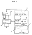
- Fig. 5 is a control block diagram showing the control relation between the detection circuit 17 and the control section 6.
- the detection circuit 17 is used a CR oscillating circuit 29 which is provided with a resistor R and responsive to the reference electrical capacitance Cr developed due to the reference electrodes 22 and further the detection electrical capacitance Cw developed due to the detection electrodes 21.
- Illustrated at numeral 30 is a switching means which is controlled by a change-over gate signal control means 31 of the control section 6 so that the reference electrical capacitance Cr and the detection electrical capacitance Cw are selectively coupled to the oscillating circuit 29 which in turn outputs a signal with an oscillating frequency fr corresponding to the reference electrical capacitance Cr and a signal with an oscillating frequency fw corresponding to the detection electrical capacitance Cw to a counter means 32 of the control section 6.
- the outputs (fr, fw) of the counter means 32 are temporarily stored in a random access memory (RAM) 33, before directing to a calculation means 34 to calculate a frequency ratio r of the output frequencies fr and fw, for example.
- Fig. 6A shows variations of the output frequencies fr and fw of the oscillating circuit 29 with respect to time during heating operation.
- the detection oscillating frequency fw due to the detection capacitance Cw is affected by both the weight variation and temperature variation, whereas the reference oscillating frequency fr due to the reference capacitance Cr is affected by only the temperature variation.
- the frequencies fw and fr it is possible to obtain only a value corresponding to only the weight variation through subtraction or division in the calculation means 34 of the control section 6.
- a description of the division process will be given hereinbelow.
- Fig. 6B shows variation of the calculated frequency ratio r with respect time.
- Fig. 7 is a graphic illustration showing the relation between the frequency, frequency ratio and the weight.
- Fig. 8 illustrates the entire circuit arrangement of an automatic heating appliance of this embodiment.
- the control section 6 comprises a well known microcomputer including a central processing unit (CPU) and is coupled to the keyboard 4 which has a key matrix which is in turn coupled to input terminals I0 to I3.
- the indication means 5 comprising a fluorescence indicating tube effects dynamic lighting in response to digit signals S0 to S4 and indication data signal 00 to 07.
- the driver 11 comprises a relay 35 and a voltage-increasing section 36 and supplies an electric power to the magnetron 10 in accordance with a RLY signal.
- the detection circuit 17 includes a single oscillating circuit 29 (operational amplifier TL082, for example) comprising a combination of a sawtooth oscillator and a waveform shaping circuit and further includes the switching means 30.
- the switching means 30 alternately switches the detection capacitance Cw and the reference capacitance Cr which are in turn inputted into an input terminal TC of a counter (counter means 32) encased in the microcomputer 6 (for example, MB88515).
- the switching operation is effected in accordance with a switching gate signal Eo.
- the switching means comprises an analog switch ( ⁇ PC4066, for example), it is also appropriate to use a semiconductor switching means or a relay circuit.
- Illustrated at numeral 37 is a level shift circuit for voltage transformation and waveform shaping, which is incorporated thereinto, if required.
- Fig. 9 is a flow chart showing operation to be executed in the microcomputer 6 in accordance with a predetermined program prestored in a memory thereof.
- the microcomputer starts with a step 101 to check the contents of the operated instruction key, for example, whether the thawing key is operated by a user. If so, control goes to a step 102 in order to detect the total weight Wo of an object to be heated prior to heating.
- a step 101 to check the contents of the operated instruction key, for example, whether the thawing key is operated by a user. If so, control goes to a step 102 in order to detect the total weight Wo of an object to be heated prior to heating.
- an attachment made of an appropriate resin, which is arranged so as to drop down water or gravy from a frozen food onto the turntable 8 to allow the food to be separated from the water or gravy.
- a step 104 is executed in order to calculate a thrawing time T D as a function of the obtained net weight W F .
- the heating time is determined in stages with the heating power being gradually decreased.
- the thawing time T D may be set as follows.
- T D T1 + T2 + T3 + T4 (5)
- T1 represents time for a high-power heating stage
- T2 designates time for a heating interruption stage
- T3 denotes time for a middle-power thawing stage
- T4 is time for a low-power finishing stage.
- the time Tn for each of the stages can be expressed as follows.
- Tn An W F + Bn (6)
- control advances to a step 105 to start the heating, followed by a step 106 to control the heating time and the high-frequency output to the heating means 10.
- the heating is automatically terminated in a step 107.
- Fig. 10A is a time chart for an understanding of the power supply to the heating means 10.
- control goes to a step 108 in order to check whether the heating instruction key is operated. If the answer of the step 108 is "NO", other process will be effected. If so, control goes to a step 109 to start the heating operation.
- the heating operation should be required to be executed so as not to receive influence of vibration and disturbance with respect to the weight sensor. Therefore, after the start of the heating, a step 110 is executed to detect the initial weight Wi of the object to be heated and a step 111 is then executed to have a wait for a predetermined time period.
- a step 112 is performed to detect the weight Wn of the heated object, then followed by a step 113 to calculate the difference DW between the successively detected weights as follows.
- DW Wn - Wn-1 (7)
- the weight of the heated object is not virtually varied and therefore the value of DW corresponds to only the output variation due to the temperature characteristics of the circuits and elements.
- vapors and so on are started to be generated from the heated object so as to decrease the weight of the heated object.
- the completion timing of th heating can be controlled in accordance with the variation of the weight of the heated object.
- the difference DW can be considered to be the time change rate of the weight variation, i.e., the time differential value. Accordingly, it is possible to check whether the obtained difference value DW results from the normal weight decrease of the heated object by comparing the difference value DW with predetermined values.
- the difference value DW is compared with two predetermined values (constants) C1 and C2 as follows. C1 ⁇ DW ⁇ C2 (8) That is, if the difference value DW is greater than the value C1, the difference value DW includes the decrease in the weight of the heated object in addition to the value due to the temperature characteristics of the devices. Further, if smaller than the value C2, the difference value DW is the normal weight decrease value of the heated object without including the value due to the noises such as vibration from the external.
- control advances to a step 115 to add the difference value DW so that the difference weight DW is integrated so as to obtain the weight variation ⁇ W as follows.
- ⁇ W ⁇ DW (9)
- the difference value DW is considered to be a value due to the output variation caused by the temperature characteristics of the devices and others and therefore the difference value DW is not used in this process.
- the difference value DW is greater than the value C2
- the difference value Dw is considered to be based on noises and so on and is not used as data in this process.
- the difference value integration weight ⁇ W accurately corresponds to the weight variation of the heated object.
- the integration value ⁇ W is compared with a threshold value W TH in a step 116 so as to check whether the weight variation reaches a predetermined value. If exceeding the threshold value W TH , the heating of the object advances to a predetermined level and hence the power supply to the heating means 10 is changed or terminated in a step 117.
- Fig. 10B is a time chart for understanding the above-mentioned heating operation due to the operation of the heating instruction key. The time T1 reaching the threshold value W TH is counted, and then the heating is continuously performed with a low output for a predetermined time period KT1 where K is a constant, for example.
- Fig. 11 is a flow chart showing a control program for the weight sensor.
- This program starts with a step 201 to set the gate signal Eo to the high-level state, then followed by a step 202 to provide a delay time and further followed by a step 203 to start the counter coupled to the TC terminal, thereby starting the detection of the reference frequency fr.
- Control further advances to a step 204 to count the gate time (for example, 1 second). After elapse of the time, the counter is stopped in a step 205. and the result fr is stored in the RAM 33 in a step 206. Thereafter, control goes to a step 207 to change the gate signal Eo to the low-level state, then followed by steps208 to 212 to similarly perform the measurement of the detection frequency fw.
- the frequencies fr and fw stored in the RAM 33 are processed so as to obtain the frequency ratio r in a step 213 and the weight w is calculated on the basis of the obtained frequency ratio r.
- Fig. 12 showing the measurement results of the temperature characteristic of the operating frequency f of an oscillating circuit, where the operating frequency f indicated on the horizontal axis is varied by variation of the capacitance or resistance and the temperature characteristic ⁇ f is obtained in accordance with the following equation.
- ⁇ f (f20 - f ⁇ )/ ⁇ f20 x ( ⁇ - 20) ⁇ (10) where f20 represent a frequency under the condition of the temperature of 20°C and f ⁇ designates a frequency under the condition of the temperature of ⁇ °C.
- Fig. 12 shows that irrespective of keeping small the temperature characteristic of the sensor, the temperature characteristic of the oscillating circuit is kept as it is and developed in accordance with the operating frequency so that the temperature characteristic increases with the heightening frequency.
- the temperature characteristic depends upon the operating frequency.
- the temperature characteristic can be completely eliminated.
- the temperature characteristic due to the circuit is developed accordingly.
- the capacitances of the detection electrodes and the reference electrodes are selectively determined with respect to the weight of the turntable 8.
- Fig. 13 shows the relation between the capacitances of the detection electrodes and reference electrodes (reference and detection frequencies) and the weight of the object to be measured (heated) (load applied to the sensor), where the horizontal axis represents the weight w of the object to be measured and the vertical axis represents the output frequency of the detection means and the frequency ratio r.
- Fig. 14 is a graphic illustration of the relation between the capacitances of the detection electrodes and reference electrodes and the weight of the object to be measured in another example.
- an automatic heating appliance for controlling heating of an object in response to operation of instruction keys and on the basis of the weight of an object to be heated.
- the appliance includes therein a heating chamber for housing the object, a heater provided on or in the heating chamber for heating the object placed therein, and a turntable provided in the heating chamber for keeping thereon the object during heating.
- a weight detector for obtaining first weight data in response to the object being placed on the turntable and a temperature compensator for obtaining a second weight data in response to the object being placed thereon, the temperature compensator substantially having the same temperature characteristic as the weight detector.
- a control unit of the appliance is responsive to the first and second weight data in order to remove an error component due to variation of the characteristic of the weight detector by variation of temperature in accordance with the result of comparison between the first and second weight data so as to determine a weight resulting from only the object.
- the control unit controls the heating of the object in accordance with variation of the determined object weight.
Landscapes
- Physics & Mathematics (AREA)
- Electromagnetism (AREA)
- Engineering & Computer Science (AREA)
- Chemical & Material Sciences (AREA)
- Combustion & Propulsion (AREA)
- Mechanical Engineering (AREA)
- General Engineering & Computer Science (AREA)
- Electric Ovens (AREA)
- Control Of High-Frequency Heating Circuits (AREA)
Claims (9)
- Automatische Heizvorrichtung mit einer darin befindlichen Heizkammer (7) zum Aufnehmen eines zu erhitzenden Gegenstandes (9), mit:
einer Heizeinrichtung (10), die auf oder in der Heizkammer (7) zum Erhitzen des in die Heizkammer (7) gelegten Gegenstands (9) gemäß einem Heizsteuersignal gebildet ist;
einer Tischvorrichtung (8), die in der Heizkammer (7) zum Aufnehmen des Gegenstands (9) während des Heizens gebildet ist;
einer Befehlstasteneinrichtung (4) einschließlich einer Auftau-Befehlstaste zum Vorgeben von Befehlen, um den Gegenstand (9) von einer Temperatur unter Null aufzutauen, und einer Heiz-Befehlstaste zum Vorgeben von Befehlen, um den Gegenstand (9) auf eine vorbestimmte Temperatur zu erhitzen;
einer Gewichtserfassungseinrichtung (15) zum Erhalten erster Gewichtsdaten ansprechend auf den auf die Tischvorrichtung (8) gelegten Gegenstand (9);
einer Temperaturausgleichseinrichtung (16) mit im wesentlichen gleicher Temperatur-Charakteristik wie die Gewichtserfassungseinrichtung (15) zum Erhalten zweiter Gewichtsdaten ansprechend auf den auf die Tischvorrichtung (16) gelegten Gegenstand (9);
einer Steuereinrichtung (6), die mit der Befehlstasteneinrichtung (4) gekoppelt ist, um ansprechend auf eine Betätigung der Befehlstasteneinrichtung (4) eine Erhitzung des Gegenstands (9) durch Ausgeben des Heizsteuersignals an die Heizeinrichtung (10) zu steuern, und die weiter mit der Gewichtserfassungseinrichtung (15) und der Temperaturausgleichseinrichtung (16) gekoppelt ist, um die Erhitzung des Gegenstands (9) auf der Grundlage des erfaßten Gewichts des Gegenstands (9) zu steuern,
dadurch gekennzeichnet, daß
die Steuereinrichtung (6) eine Fehlerkomponente aufgrund einer durch Temperaturveränderung veränderten Charakteristik der Gewichtserfassungseinrichtung (15) gemäß dem Vergleichsergebnis zwischen den von der Gewichtserfassungseinrichtung (15) erhaltenen ersten Gewichtsdaten und den von der Temperaturausgleichseinrichtung (16) erhaltenen zweiten Gewichtsdaten beseitigt, um ausschließlich ein Gewicht des Gegenstands (9) zu bestimmen, und
die Steuereinrichtung (6) ansprechend auf eine Betätigung der Auftau-Befehlstaste stufenweise eine Heizzeit mit allmählich abnehmender Heizenergie auf der Grundlage des Gewichts des Gegenstands (9) vor dem Erhitzen berechnet und ansprechend auf eine Betätigung der Heiz-Befehlstaste, die Gewichtsveränderung des Gegenstands (9) während dem Erhitzen erfaßt und zum Beenden des Heizens bestimmt ist. - Automatische Heizvorrichtung nach Anspruch 1,
dadurch gekennzeichnet, daß
die Gewichtserfassungseinrichtung (15, 16) aus einem elektrischen kapazitiven Druckmeßwertgeber besteht, der ein Paar aus flachen Platten gebildete und einander in einem vorbestimmten Abstand gegenüberstehende Erfassungselektroden (21) enthält, die jeweils um das Paar Erfassungselektroden (21) herum gebildet sind. - Automatische Heizvorrichtung nach Anspruch 2,
dadurch gekennzeichnet, daß
die Temperaturausgleichseinrichtung (16) in der Nähe der Gewichtserfassungseinrichtung (15) angeordnet ist. - Automatische Heizvorrichtung nach Anspruch 3,
dadurch gekennzeichnet, daß
die Gewichtserfassungseinrichtung (15, 16) eine Erfassungseinrichtung zum Erfassen einer elektrischen Kapazität (Cw) des Erfassungselektrodenpaars (21) und einer elektrischen Kapazität (Cr) des Bezugselektrodenpaars (22) enthält und die Steuereinrichtung (6) auf die erfaßte Kapazität (Cw) der Erfassungselektroden (21) und die erfaßte Kapazität (Cr) der Bezugselektroden (22) reagiert, um das Gewicht des Gegenstands (9) auf der Grundlage der beiden erfaßten Kapazitäten (Cw, Cr) zu berechnen. - Automatische Heizvorrichtung nach Anspruch 4,
dadurch gekennzeichnet, daß
die erfaßte Kapazität (Cw) der Erfassungselektroden (21) und die erfaßte Kapazität (Cr) der Bezugselektroden (22) abwechselnd der Steuereinrichtung (6) zugeführt werden. - Automatische Heizvorrichtung nach Anspruch 4,
dadurch gekennzeichnet, daß
die Steuereinrichtung (6) das Gewicht des Gegenstands (9) auf der Grundlage des Verhältnisses (r) der erfaßten Kapazität (Cw) der Erfassungselektroden (21) und der Kapazität (Cr) der Bezugselektroden (22) berechnet. - Automatische Heizvorrichtung nach Anspruch 2 oder 3,
dadurch gekennzeichnet, daß
die Erfassungselektroden (21) und die Bezugselektroden (22) derart angeordnet sind, daß eine auf die Gewichtserfassungseinrichtung (15, 16) aufgebrachte Last (P), bei der eine elektrische Kapazität der Erfassungselektroden (21) und eine elektrische Kapazität der Bezugselektroden (22) im wesentlichen gleich groß sind, einen Wert zwischen dem Gewicht der Tischvorrichtung (8) allein und einem maximal auf die Gewichtserfassungseinrichtung (15, 16) aufzubringenden Gewicht besitzt. - Automatische Heizvorrichtung nach Anspruch 2 oder 3,
dadurch gekennzeichnet, daß
die Erfassungselektroden (21) und die Bezugselektroden (22) derart angeordnet sind, daß eine auf die Gewichtserfassungseinrichtung (15, 16) aufgebrachte Last (P), bei der eine elektrische Kapazität (Cw) der Erfassungselektroden (21) und eine elektrische Kapazität (Cr) der Bezugselektroden (22) im wesentlichen gleich groß sind, das gleiche Gewicht wie die Tischvorrichtung (8) allein besitzt. - Automatische Heizvorrichtung nach Anspruch 7,
dadurch gekennzeichnet, daß
die auf die Gewichtserfassungseinrichtung (15, 16) aufgebrachte Last (P), bei der die elektrische Kapazität (Cw) der Erfassungselektroden (21) und die elektrische Kapazität (Cr) der Bezugselektroden (22) im wesentlichen gleich groß sind, die Hälfte der Differenz zwischen dem Gewicht der Tischvorrichtung (8) allein und einem maximal auf die Gewichtserfassungseinrichtung (15, 16) aufzubringenden Gewicht beträgt.
Applications Claiming Priority (4)
| Application Number | Priority Date | Filing Date | Title |
|---|---|---|---|
| JP220962/88 | 1988-09-02 | ||
| JP63220963A JP2553659B2 (ja) | 1988-09-02 | 1988-09-02 | 高周波加熱装置 |
| JP63220962A JPH0823514B2 (ja) | 1988-09-02 | 1988-09-02 | 圧力検出装置 |
| JP220963/88 | 1988-09-02 |
Publications (2)
| Publication Number | Publication Date |
|---|---|
| EP0359976A1 EP0359976A1 (de) | 1990-03-28 |
| EP0359976B1 true EP0359976B1 (de) | 1994-06-01 |
Family
ID=26523996
Family Applications (1)
| Application Number | Title | Priority Date | Filing Date |
|---|---|---|---|
| EP89114758A Expired - Lifetime EP0359976B1 (de) | 1988-09-02 | 1989-08-09 | Automatische Heizvorrichtung mit Gewichtsmesswertgeber |
Country Status (6)
| Country | Link |
|---|---|
| US (1) | US4970374A (de) |
| EP (1) | EP0359976B1 (de) |
| KR (1) | KR920003433B1 (de) |
| AU (1) | AU620435B2 (de) |
| CA (1) | CA1323668C (de) |
| DE (1) | DE68915662T2 (de) |
Families Citing this family (29)
| Publication number | Priority date | Publication date | Assignee | Title |
|---|---|---|---|---|
| KR930001675B1 (ko) * | 1989-04-14 | 1993-03-08 | 가부시끼가이샤 히다찌세이사꾸쇼 | 비디오카메라의 화이트밸런스 조정장치 |
| IT1237959B (it) * | 1990-02-01 | 1993-06-19 | Eurodomestici Ind Riunite | Metodo e dispositivo per il rilevamento del peso di alimenti posti in un forno a microonde e per controllarne il trattamento |
| IT1238453B (it) * | 1990-02-01 | 1993-08-18 | Eurodomestici Ind Riunite | Metodo e dispositivo per il rilevamento del peso di un alimento posto in un forno a microonde al fine di comandare la potenza di funzionamento del magnetron e controllare il trattamento dell'alimento stesso |
| US5349138A (en) * | 1992-04-21 | 1994-09-20 | Goldstar Co., Ltd. | Food weight sensing device for microwave oven |
| KR950004637Y1 (ko) * | 1992-09-09 | 1995-06-12 | 구자홍 | 전자레인지의 조리물 중량 검출장치 |
| US5565655A (en) * | 1992-11-19 | 1996-10-15 | Goldstar Co., Ltd. | Method of detecting food weight in microwave oven by processing weight sensor signals |
| SE500823C2 (sv) * | 1993-01-29 | 1994-09-12 | Whirlpool Europ | Mikrovågsugn med vägningsanordning |
| US5553486A (en) * | 1993-10-01 | 1996-09-10 | Hysitron Incorporated | Apparatus for microindentation hardness testing and surface imaging incorporating a multi-plate capacitor system |
| US5576483A (en) * | 1993-10-01 | 1996-11-19 | Hysitron Incorporated | Capacitive transducer with electrostatic actuation |
| EP0721564B1 (de) * | 1993-10-01 | 2000-09-13 | Hysitron Incorporated | Hochpräzisionswaage und positionssensor |
| US6026677A (en) * | 1993-10-01 | 2000-02-22 | Hysitron, Incorporated | Apparatus for microindentation hardness testing and surface imaging incorporating a multi-plate capacitor system |
| US5661235A (en) * | 1993-10-01 | 1997-08-26 | Hysitron Incorporated | Multi-dimensional capacitive transducer |
| US5652710A (en) * | 1993-12-10 | 1997-07-29 | Matsushita Electric Industrial Co., Ltd. | Solid/liquid determination apparatus |
| SE502883C2 (sv) * | 1994-06-13 | 1996-02-12 | Whirlpool Europ | Styrförfarande för en mikrovågsugn, mikrovågsugn och dess användning för tillagning/uppvärmning av en matvara enligt styrförfarandet |
| KR100218958B1 (ko) * | 1996-02-23 | 1999-09-01 | 윤종용 | 전자렌지의 트레이 구동 제어방법 |
| KR0182714B1 (ko) * | 1996-02-23 | 1999-03-20 | 김광호 | 전자렌지의 구동제어방법 |
| US6227041B1 (en) | 1998-09-17 | 2001-05-08 | Cem Corporation | Method and apparatus for measuring volatile content |
| DE19964217A1 (de) * | 1999-06-10 | 2001-05-17 | Bsh Bosch Siemens Hausgeraete | Kochfeld mit Wägeeinheit |
| KR20030060667A (ko) * | 2002-01-10 | 2003-07-16 | 최승팔 | 장식용 목판 |
| EP1991813B1 (de) * | 2006-03-08 | 2011-09-07 | Premark FEG L.L.C. | Kochverfahren für einen kombiofen |
| EP1994360A4 (de) * | 2006-03-13 | 2012-03-14 | Asylum Research Corp | Nanoindenter |
| WO2007133675A2 (en) * | 2006-05-11 | 2007-11-22 | Loadstar Sensors, Inc. | Capacitive force-measuring device based load sensing platform |
| TWI295557B (en) * | 2006-09-05 | 2008-04-11 | Fego Prec Ind Co Ltd | Roast device for controlling fixes power and roast method for the same |
| GB0913704D0 (en) * | 2009-08-05 | 2009-09-16 | Next Row Ltd | Induction heating unit for hair rollers |
| WO2015135788A1 (en) * | 2014-03-11 | 2015-09-17 | Koninklijke Philips N.V. | Method and apparatus for controlling a cooking process of a food |
| US20180268358A1 (en) * | 2015-01-09 | 2018-09-20 | Apex Industrial Technologies Llc | Order fulfillment system and method with item sensor |
| CN112996161B (zh) * | 2019-12-13 | 2022-08-23 | 青岛海尔电冰箱有限公司 | 用于加热装置的控制方法及加热装置 |
| CN114459586B (zh) * | 2020-11-09 | 2023-04-18 | 青岛海尔电冰箱有限公司 | 冷冻冷藏装置内称重装置的校准方法和冷冻冷藏装置 |
| CN118854739B (zh) | 2024-08-19 | 2025-05-02 | 鄂尔多斯市路泰新材料科技发展有限公司 | 一种厂拌温、热再生沥青混合料生产工艺、装备及系统 |
Family Cites Families (14)
| Publication number | Priority date | Publication date | Assignee | Title |
|---|---|---|---|---|
| GB1215060A (en) * | 1967-07-28 | 1970-12-09 | Lauro Ferrarini | Process and apparatus for heat processing salted meats |
| FR2475231A1 (fr) * | 1980-02-04 | 1981-08-07 | Testut Aequitas | Dispositif de mesure de capacite, en particulier pour instrument de pesage |
| US4441002A (en) * | 1980-09-24 | 1984-04-03 | Raytheon Company | Cook-by-weight microwave oven |
| US4649759A (en) * | 1981-05-19 | 1987-03-17 | Setra Systems, Inc. | Force transducer |
| GB2123157B (en) * | 1982-06-22 | 1986-10-15 | Peter Caleb Frederi Wolfendale | Load cells |
| US4461363A (en) * | 1982-07-26 | 1984-07-24 | Hoffmann-La Roche Inc. | High-speed capacitive weighing method and apparatus |
| US4521658A (en) * | 1984-01-16 | 1985-06-04 | Amana Refrigeration, Inc. | Microwave oven scale apparatus |
| US4595827A (en) * | 1984-05-02 | 1986-06-17 | Matsushita Electric Industrial Co., Ltd. | Cooking apparatus with weighing device |
| JPS60258895A (ja) * | 1984-06-04 | 1985-12-20 | 松下電器産業株式会社 | 高周波加熱装置 |
| US4672181A (en) * | 1984-07-30 | 1987-06-09 | Matsushita Electric Industrial, Co., Ltd. | Heating apparatus having a weight detector |
| KR900002321B1 (ko) * | 1984-10-18 | 1990-04-11 | 샤프 가부시끼가이샤 | 가열 조리기의 중량 검출장치 |
| GB2173902B (en) * | 1985-04-16 | 1988-12-21 | Sharp Kk | Food weight measuring device for cooking appliance |
| US4591684A (en) * | 1985-04-16 | 1986-05-27 | Sharp Kabushiki Kaisha | Cooking completion detection in a cooking appliance |
| SE452838B (sv) * | 1985-07-18 | 1987-12-14 | Philips Norden Ab | Forfarande for uppvermning av livsmedel i ugn samt mikrovagsugn for utforande enligt forfarandet |
-
1989
- 1989-08-02 US US07/388,389 patent/US4970374A/en not_active Expired - Lifetime
- 1989-08-09 EP EP89114758A patent/EP0359976B1/de not_active Expired - Lifetime
- 1989-08-09 DE DE68915662T patent/DE68915662T2/de not_active Expired - Lifetime
- 1989-08-21 KR KR1019890011860A patent/KR920003433B1/ko not_active Expired
- 1989-08-28 AU AU40847/89A patent/AU620435B2/en not_active Expired
- 1989-08-30 CA CA000609874A patent/CA1323668C/en not_active Expired - Lifetime
Also Published As
| Publication number | Publication date |
|---|---|
| AU620435B2 (en) | 1992-02-20 |
| KR920003433B1 (ko) | 1992-05-01 |
| DE68915662T2 (de) | 1994-10-20 |
| CA1323668C (en) | 1993-10-26 |
| AU4084789A (en) | 1990-03-08 |
| EP0359976A1 (de) | 1990-03-28 |
| DE68915662D1 (de) | 1994-07-07 |
| US4970374A (en) | 1990-11-13 |
| KR910004998A (ko) | 1991-03-29 |
Similar Documents
| Publication | Publication Date | Title |
|---|---|---|
| US4970374A (en) | Automatic heating appliance with weight sensor | |
| EP0238022B1 (de) | Heizgerät | |
| US5530229A (en) | Heating time control apparatus and method thereof for microwave oven | |
| EP0595569B1 (de) | Heizapparat | |
| EP0146406B1 (de) | Automatisches Heizgerät | |
| KR890003255A (ko) | 전자 제어식 조리기 | |
| KR0154643B1 (ko) | 증기센서의 출력신호를 이용한 적응 제어방법 | |
| EP0093173A1 (de) | Hochfrequenz-heizvorrichtung | |
| US4442344A (en) | Sensor controlled cooking apparatus | |
| US6670591B2 (en) | Microwave oven | |
| EP0517433A1 (de) | Heizapparat | |
| KR0128559B1 (ko) | 전자렌지의 습도센서 리드타임 제어방법 | |
| EP1353535B1 (de) | Verfahren und Vorrichtung zur Steuerung eines Mikrowellenofen | |
| KR940004978B1 (ko) | 전자레인지의 가열 제어장치 및 제어방법 | |
| KR0162322B1 (ko) | 전자레인지의 가열시간 제어장치 및 방법 | |
| JPH02106617A (ja) | 加熱装置 | |
| JP2532603B2 (ja) | 高周波加熱装置 | |
| KR0154625B1 (ko) | 중량센서의 영점 조정방법 | |
| KR0142491B1 (ko) | 증기센서를 이용한 전자렌지의 오동작 제어장치 및 제어방법 | |
| KR940003015B1 (ko) | 초전센서를 이용한 전자레인지의 자동 가열장치 | |
| JPH0317132Y2 (de) | ||
| KR940008520B1 (ko) | 전자레인지의 자동 해동장치와 방법 | |
| KR950001466B1 (ko) | 초전센서와, 이 초전센서를 이용한 전자레인지의 자동 가열장치와 방법 | |
| JPS63101626A (ja) | 調理器 | |
| JP2521689B2 (ja) | 調理器 |
Legal Events
| Date | Code | Title | Description |
|---|---|---|---|
| PUAI | Public reference made under article 153(3) epc to a published international application that has entered the european phase |
Free format text: ORIGINAL CODE: 0009012 |
|
| 17P | Request for examination filed |
Effective date: 19890809 |
|
| AK | Designated contracting states |
Kind code of ref document: A1 Designated state(s): DE FR GB IT SE |
|
| 17Q | First examination report despatched |
Effective date: 19930401 |
|
| GRAA | (expected) grant |
Free format text: ORIGINAL CODE: 0009210 |
|
| AK | Designated contracting states |
Kind code of ref document: B1 Designated state(s): DE FR GB IT SE |
|
| ET | Fr: translation filed | ||
| REF | Corresponds to: |
Ref document number: 68915662 Country of ref document: DE Date of ref document: 19940707 |
|
| ITF | It: translation for a ep patent filed | ||
| PG25 | Lapsed in a contracting state [announced via postgrant information from national office to epo] |
Ref country code: SE Effective date: 19940901 |
|
| PLBE | No opposition filed within time limit |
Free format text: ORIGINAL CODE: 0009261 |
|
| STAA | Information on the status of an ep patent application or granted ep patent |
Free format text: STATUS: NO OPPOSITION FILED WITHIN TIME LIMIT |
|
| 26N | No opposition filed | ||
| REG | Reference to a national code |
Ref country code: GB Ref legal event code: IF02 |
|
| PGFP | Annual fee paid to national office [announced via postgrant information from national office to epo] |
Ref country code: DE Payment date: 20080821 Year of fee payment: 20 |
|
| PGFP | Annual fee paid to national office [announced via postgrant information from national office to epo] |
Ref country code: IT Payment date: 20080827 Year of fee payment: 20 Ref country code: FR Payment date: 20080818 Year of fee payment: 20 |
|
| PGFP | Annual fee paid to national office [announced via postgrant information from national office to epo] |
Ref country code: GB Payment date: 20080820 Year of fee payment: 20 |
|
| PG25 | Lapsed in a contracting state [announced via postgrant information from national office to epo] |
Ref country code: GB Free format text: LAPSE BECAUSE OF EXPIRATION OF PROTECTION Effective date: 20090808 |