EP0360001B1 - Dispositif de fixation de plaques à un mur, notamment des plaques en céramique - Google Patents
Dispositif de fixation de plaques à un mur, notamment des plaques en céramique Download PDFInfo
- Publication number
- EP0360001B1 EP0360001B1 EP89115208A EP89115208A EP0360001B1 EP 0360001 B1 EP0360001 B1 EP 0360001B1 EP 89115208 A EP89115208 A EP 89115208A EP 89115208 A EP89115208 A EP 89115208A EP 0360001 B1 EP0360001 B1 EP 0360001B1
- Authority
- EP
- European Patent Office
- Prior art keywords
- mounting element
- panels
- panel
- stem
- foot
- Prior art date
- Legal status (The legal status is an assumption and is not a legal conclusion. Google has not performed a legal analysis and makes no representation as to the accuracy of the status listed.)
- Expired - Lifetime
Links
- 239000000919 ceramic Substances 0.000 title claims abstract description 5
- 235000001674 Agaricus brunnescens Nutrition 0.000 claims abstract description 3
- 238000005253 cladding Methods 0.000 claims description 10
- 229910052782 aluminium Inorganic materials 0.000 claims description 2
- XAGFODPZIPBFFR-UHFFFAOYSA-N aluminium Chemical compound [Al] XAGFODPZIPBFFR-UHFFFAOYSA-N 0.000 claims description 2
- 239000002991 molded plastic Substances 0.000 claims description 2
- 239000004411 aluminium Substances 0.000 claims 1
- 238000002347 injection Methods 0.000 claims 1
- 239000007924 injection Substances 0.000 claims 1
- 239000000243 solution Substances 0.000 description 7
- 230000008878 coupling Effects 0.000 description 3
- 238000010168 coupling process Methods 0.000 description 3
- 238000005859 coupling reaction Methods 0.000 description 3
- 238000004873 anchoring Methods 0.000 description 2
- 238000010276 construction Methods 0.000 description 2
- 241000238876 Acari Species 0.000 description 1
- 230000015572 biosynthetic process Effects 0.000 description 1
- 230000000694 effects Effects 0.000 description 1
- 230000005484 gravity Effects 0.000 description 1
- 230000037431 insertion Effects 0.000 description 1
- 238000003780 insertion Methods 0.000 description 1
- 229910052751 metal Inorganic materials 0.000 description 1
- 239000002184 metal Substances 0.000 description 1
Images

Classifications
-
- E—FIXED CONSTRUCTIONS
- E04—BUILDING
- E04F—FINISHING WORK ON BUILDINGS, e.g. STAIRS, FLOORS
- E04F13/00—Coverings or linings, e.g. for walls or ceilings
- E04F13/07—Coverings or linings, e.g. for walls or ceilings composed of covering or lining elements; Sub-structures therefor; Fastening means therefor
- E04F13/08—Coverings or linings, e.g. for walls or ceilings composed of covering or lining elements; Sub-structures therefor; Fastening means therefor composed of a plurality of similar covering or lining elements
- E04F13/0801—Separate fastening elements
- E04F13/0803—Separate fastening elements with load-supporting elongated furring elements between wall and covering elements
- E04F13/081—Separate fastening elements with load-supporting elongated furring elements between wall and covering elements with additional fastening elements between furring elements and covering elements
- E04F13/0814—Separate fastening elements with load-supporting elongated furring elements between wall and covering elements with additional fastening elements between furring elements and covering elements fixed by means of clamping action
Definitions
- the present invention relates to a wall covering with a device for fastening plates to a wall, in particular ceramic plates.
- a device according to this invention is described, for example, in CH-A-563510.
- This prior publication shows a ceiling and wall cladding, consisting of plate-shaped cladding elements which are separately detachably attached to parallel mounting rails with the aid of holders, the heads of which can be moved in a groove and through Can be fixed in the groove around an axis running at right angles to the wall surface. These holders are not secured against the risk of rotation.
- EP-A-0223106 also shows, in a frame construction made of two components, a rotating part as a releasable coupling, which can be rotated from the outside in its longitudinal axis by approximately 90 ° into its coupling or decoupling position. In its coupling position, this rotating part is positively secured at one end with anchoring means against the risk of rotation.
- DE-A-2634774 shows a locking of the securing members provided for fastening by means of positive engagement of two parts with one another.
- EP-A-0 287 973 which is considered a European application and whose content is prior art in accordance with Articles 54 (3) and (4) EPC, shows a wall covering with a device for fastening panels to a wall.
- this device includes an arrangement of horizontal supports, the mutual distance of which corresponds to the height of each facade element, the horizontal supports having a double groove in their horizontal plane of symmetry, consisting of two retaining lips, for receiving and fixing a fastening T-piece by rotation.
- the T-piece has the shape of a mushroom and its base, the two corners of which are opposite to the plane of symmetry and have a strong rounding, is thus designed for the bayonet-type closure with the double groove of the horizontal profile, the web of the T-piece having a rectangular cross section.
- the dead weight of the upper facade element rests on the wider side of the rectangular web of the T-piece, which prevents the fastening element from twisting.
- the head of the fastener holds the subsequent facade elements against lateral tilting.
- the object of the present invention is therefore a wall covering with a device for fastening panels to a wall, in particular Kera microplates, to create, in which the panels can be fixed in a simple but safe manner to the vertical wall of a building, for example as a so-called ventilated facade or just as a weatherproof skin of the building, both the assembly of the panels and their disassembly can be carried out easily and without the use of special tools.
- the foot of the fastening element consists of a rectangular piece, the two corners of which lie opposite the axis of symmetry and have a strong curve, while the mounting rail for fastening the fastening elements has a centrally symmetrical groove profile which forms the opening towards the front and has two retaining lips, in which the foot of the fastener engages.
- the head carries an extension with a rectangular cross-section, on which the upper plate rests at least partially.
- 1 denotes the top plate of a row of plates (not shown) of a facade cladding.
- the plate 1 is preferably, but not exclusively, a ceramic plate.
- panel 1 is a weatherproof cladding panel for building facades, the weight of which is relatively high and also normally has a thickness of several millimeters.
- Such panels are attached to the masonry (not shown) of the facade directly above a support profile 3 or as a so-called ventilated facade.
- the type of substructure of the facade does not form the subject of this invention, in which it is only important that each row of panels is supported by its own horizontal support rail 3.
- the present invention can be used not only for so-called ventilated facades, but wherever a facade made of panels has to be realized.
- FIG. 2 in FIG. 2 denotes the lower plate of a lower row of plates, and between the plate 1 and the similar plate 2 there is a horizontal joint 4, which is formed from the distance of the two plates in height.
- the plates 1 and 2 of each row are, as mentioned, carried by a horizontal support profile 3. It does not matter how this profile 3 is designed in detail.
- the only decisive factor in the sense of the invention is the fact that the profile 3 has a double groove 5.
- This term is to be understood here to mean a groove formed from two opposing L-profiles, which form the retaining lips 6 and 7, which protrudes from a perpendicular arm of the supporting profile 3 and thus forms a longitudinal double groove 5 which is open towards the front.
- the foot 9 of a fastening element 10 can engage, which has a narrower side a , smaller than the width b of the opening of the double groove 5, and a wider side c , wider than the width b of the opening of the double groove, but narrower than that inner width d of the double groove itself.
- the foot 9 can thus be inserted into the double groove 5 from its narrow side a and fixed in the double groove 5 by twisting.
- the foot 9 of the fastening element has a rectangular shape Form, the two corners 11 and 12 of which are opposite the axis of symmetry (see FIG. 2) have a strong rounding, so that the fastening element can only be rotated in one direction of rotation when it is introduced into the double groove 5, since after it has been screwed into the double groove 5 the other two sharp corners of the foot 9 prevent further rotation in the same sense.
- This solution offers the advantage of safe assembly, especially if, as explained later, the web of the fastening element has a bent shape and the bends all have to look on the same side.
- the fastening element 10 further has a web 13 and a head 14 according to the invention.
- the web 13 has a rectangular cross section with a wide and a narrow side and, in the assembled state of the fastening element 10, as shown in FIG. 1, an upper plate 1 rests with its weight on one of the wider sides of the web 13.
- the weight of the Plate 1 thus very effectively prevents the fastener 10 from rotating under the action of external forces, such as vibrations, gusts of wind, etc., and thus could move into such a transverse position of its foot that the fastener itself slips out of the Double groove permitted.
- the desired rotation lock of the fastening element 10, which corresponds to the object of the invention, is thus realized without special fixing elements and without any deformation of the parts of the fastening element or other parts, but only by gravity.
- the head 14 of the fastening element has no supporting function, but rather ensures that at least one plate 1 of the upper row and one plate 2 of the lower row are held against lateral tilting. For this purpose it is sufficient that the head 14 guides the plates 1 and 2 with or without play. As a rule, each head 14 holds only an upper and a lower plate 1 or 2 without tilting. But if the fastener at the intersection between four adjacent plates, two of the upper and two of the lower row, the head 14 can hold all four plates in the appropriate place against lateral tilting.
- the plates are assembled in a simple manner starting from the bottom. This means that first the fastening elements 10 of the lowest row of plates are mounted, which is done by screwing into the double groove 5, and then the plates are supported on the lower edge thereof. By mounting the fasteners 10 of the next higher row of plates, the plates of the lower row are secured against lateral tilting. This work is then repeated for each row of panels until the entire facade is occupied.
- each plate with the web 13 of the upper fastening element 10 has such a play that by lifting each plate of a row of plates between the same and the plate below, a gap is created, the width of which is greater than the width a of the narrower side of the foot 9 . It is thus possible, by simply lifting the upper plate, to create space for the rotation of the fastening element 10 in the sense of its solution from the double groove 5, with which the fastening element can be threaded out and removed. Each panel can thus be removed and replaced individually without having to move additional panels when the facade is fully assembled. It goes without saying that the dimensions of the head 14 must take into account the corresponding play between the plates and the web 13.
- FIGS. 2, 3 and 4 it is further provided that the web 13 of the fastening element 10 is bent.
- This has the advantage that the horizontal gap formed between the two plates of two plates standing one above the other lies in the plane of symmetry of the support profile 3, although the lower plate is at a given distance from the web 13.
- This is merely an advantage in terms of assembly, since it is easier to mount the support profiles 3 symmetrically with respect to the horizontal joints than to produce the support profiles asymmetrically. This prevents assembly errors due to incorrect assembly of the profiles.
- the head 14 of the fastening element 10 has a slot 15, as can be seen in FIG. 4, for the use of a screwdriver for the convenient rotation of the fastening element 10.
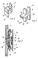
- Figures 5 and 6 also show a further preferred embodiment of the invention, namely Figure 5 in a perspective view and Figure 6 in the assembled state and seen from the side.
- the head 14 of the fastening element 10 of this variant carries an extension 16 with a rectangular cross-section, which extension 16 is essentially an extension of the web 13 and on which the upper plate 1 rests at least partially and according to the invention.
- the web 13 and / or the extension 16 can also have a bent shape in the sense of the solution in FIGS. 2 to 4 in order to achieve the same effect as explained in connection with these figures.
- the head 14 of the fastener 10 of Figures 5 and 6 performs the same task as the head of the other solutions shown. It differs from those previously described only in that it does not prevent the plates 1 or 2 from tipping sideways from the front, i.e. from the external surface of the panels, but from behind, i.e. from the back of the plates.
- the plates 1 and 2 have a e.g. formed by a bent sheet metal strip holding groove 17, in which the head 14 can be screwed or hooked into the double groove 5 in a manner similar to the foot 9.
- the fastening element 10 can also be made from a drawn aluminum profile or from an injection-molded plastic.
Landscapes
- Engineering & Computer Science (AREA)
- Architecture (AREA)
- Civil Engineering (AREA)
- Structural Engineering (AREA)
- Finishing Walls (AREA)
Claims (7)
- Revêtement mural comportant, pour fixer des plaques (1, 2) à un mur et en particulier des plaques de céramique à un mur de façade d'un bâtiment, un dispositif constitué par des profilés porteurs horizontaux (3) dont l'écartement correspond à la hauteur de chaque plaque (1, 2) et qui présentent dans leur plan horizontal de symétrie une ouverture pour recevoir un élément de fixation (10) qu'on peut mettre en place et enlever en le faisant tourner, cet élément de fixation (10) ayant la forme d'un champignon pourvu d'un pied (9), d'une tige (13) et d'une tête (14), et ce pied (9) étant prévu pour assurer une fixation à baïonnette dans l'ouverture du profilé porteur (3), la tige (13) présentant une section transversale rectangulaire, et le grand côté de cette section rectangulaire de la tige (13) étant orienté à l'horizontale en position de montage, de telle manière que dans deux rangées de plaques adjacentes dans le sens de la hauteur une plaque supérieure (1) repose sur l'un des grands côtés de cette section rectangulaire de la tige (13) d'un élément de fixation (10), empêchant ainsi cet élément de tourner, et la tête (14) de l'élément de fixation (10) retenant au moins une plaque (1) de la rangée supérieure et une plaque (2) de la rangée inférieure pour en empêcher le basculement latéral , chaque plaque (1, 2) présentant vis-à-vis de l'élément de fixation (10) qui la surmonte un jeu tel qu'en soulevant chaque plaque (1, 2) on provoque entre celle-ci et la plaque sous-jacente l'apparition d'un interstice dont la largeur est supérieure à la largeur (a) du petit côté du pied (9).
- Dispositif selon la revendication 1, caractérisé en ce que le pied (9) de l'élément de fixation (10) est constitué par une pièce rectangulaire dont deux coins (11, 12) opposés par rapport au plan de symétrie sont largement arrondis, et en ce que le profilé porteur (3) présente une rainure double et symétrique (5) formée par deux lèvres de retenue (6, 7) en saillie vers l'avant, et constituant l'ouverture dans laquelle on peut engager par son petit côté le pied (9) de l'élément de fixation (10), la largeur de cette rainure (5) permettant ensuite la rotation de l'élément de fixation (10) dans le sens où se trouvent ses coins arrondis (11, 12) mais empêchant une rotation dans le sens opposé.
- Revêtement mural selon la revendication 1, caractérisé en ce que la tige (13) de l'élément de fixation est coudée et en ce que la plaque (1) d'une rangée supérieure de plaques repose sur la partie coudée vers le haut de la tige (13), tandis que le bord supérieur de la plaque (2) d'une rangée sous-jacente présente par rapport à la tige (13) un écartement tel que l'interstice horizontal ainsi créé entre les deux plaques (1, 2) se trouve dans le plan de symétrie du profilé porteur (3).
- Revêtement mural selon la revendication 1, caractérisé en ce que l'a tête (14) de l'élément de fixation (10) présente une fente (15) pour recevoir un tournevis servant à faire tourner cet élément.
- Revêtement mural selon la revendication 1, caractérisé en ce que la tête (14) porte une saillie (16) de section transversale rectangulaire, cette saillie formant sensiblement un prolongement de la tige (13), sur lequel la plaque supérieure (1) repose au moins en partie.
- Revêtement mural selon la revendication 1, caractérisé en ce que l'élément de fixation (10) est constitué par un profilé en aluminium.
- Revêtement mural selon la revendication 1, caractérisé en ce que l'élément de fixation (10) est en matière plastique moulée par injection.
Priority Applications (1)
| Application Number | Priority Date | Filing Date | Title |
|---|---|---|---|
| AT89115208T ATE85832T1 (de) | 1988-09-22 | 1989-08-18 | Vorrichtung zum befestigen von platten an einer wand, insbesondere keramikplatten. |
Applications Claiming Priority (2)
| Application Number | Priority Date | Filing Date | Title |
|---|---|---|---|
| CH3521/88 | 1988-09-22 | ||
| CH352188 | 1988-09-22 |
Publications (2)
| Publication Number | Publication Date |
|---|---|
| EP0360001A1 EP0360001A1 (fr) | 1990-03-28 |
| EP0360001B1 true EP0360001B1 (fr) | 1993-02-17 |
Family
ID=4257799
Family Applications (1)
| Application Number | Title | Priority Date | Filing Date |
|---|---|---|---|
| EP89115208A Expired - Lifetime EP0360001B1 (fr) | 1988-09-22 | 1989-08-18 | Dispositif de fixation de plaques à un mur, notamment des plaques en céramique |
Country Status (3)
| Country | Link |
|---|---|
| EP (1) | EP0360001B1 (fr) |
| AT (1) | ATE85832T1 (fr) |
| DE (1) | DE58903563D1 (fr) |
Families Citing this family (5)
| Publication number | Priority date | Publication date | Assignee | Title |
|---|---|---|---|---|
| DE102009033389A1 (de) * | 2009-07-16 | 2011-01-20 | PINUFIN Oberflächentechnik GmbH & Co. KG | Schalung aus Profilelementen |
| WO2011150035A2 (fr) | 2010-05-28 | 2011-12-01 | The Diller Corporation | Système de bardage pour stratifiés de bâtiment |
| US9903123B1 (en) * | 2016-02-19 | 2018-02-27 | David Simonsen | Apparatus for mounting a plurality of panels to a facade |
| WO2017142614A1 (fr) * | 2016-02-19 | 2017-08-24 | Simonsen David | Appareil amélioré permettant de monter une pluralité de panneaux sur une façade |
| EP4536918A1 (fr) * | 2023-06-16 | 2025-04-16 | Martin Sonne | Raccord de panneau et panneau plat, raccord de panneau, outil d'installation pour raccords de panneau et utilisation d'un raccord de panneau |
Family Cites Families (7)
| Publication number | Priority date | Publication date | Assignee | Title |
|---|---|---|---|---|
| US2857995A (en) * | 1955-12-21 | 1958-10-28 | Kawneer Co | Wall facing |
| US3300934A (en) * | 1963-08-05 | 1967-01-31 | Robertson Co H H | Building outer wall structure |
| DE2326129A1 (de) * | 1973-05-23 | 1974-11-28 | Seger & Angermeyer Desco Werk | Befestigungsanordnung fuer eine wandverkleidung |
| DE2633171A1 (de) * | 1976-07-23 | 1978-01-26 | Herbert Lehmann | Tragkonstruktion fuer wandverkleidungen |
| DE3015255A1 (de) * | 1980-04-21 | 1981-10-22 | Grünzweig + Hartmann Montage GmbH, 6700 Ludwigshafen | Hinterlueftete fassadenbekleidung aus mechanisch an der wand befestigten bekleidungsplatten |
| DE3636565A1 (de) * | 1986-10-28 | 1988-05-05 | Cpm Ceramic Patent Management | Keramik-fassadenplatten und aus derartigen platten hergestellte fassaden |
| CH672518A5 (fr) * | 1987-04-22 | 1989-11-30 | Werner Mueller |
-
1989
- 1989-08-18 DE DE8989115208T patent/DE58903563D1/de not_active Expired - Fee Related
- 1989-08-18 EP EP89115208A patent/EP0360001B1/fr not_active Expired - Lifetime
- 1989-08-18 AT AT89115208T patent/ATE85832T1/de not_active IP Right Cessation
Also Published As
| Publication number | Publication date |
|---|---|
| DE58903563D1 (de) | 1993-03-25 |
| EP0360001A1 (fr) | 1990-03-28 |
| ATE85832T1 (de) | 1993-03-15 |
Similar Documents
| Publication | Publication Date | Title |
|---|---|---|
| EP1878847B1 (fr) | Structure de mur rideau | |
| DE69125572T2 (de) | Tragschiene für eine gläserne Tür oder Trennwand | |
| DE3711609C2 (fr) | ||
| DE3029576A1 (de) | Stuetz- und haltevorrichtung fuer tafeln, insbesondere vitrinengestell | |
| DE10344201A1 (de) | Solarmodulbefestigung, Verfahren zum Montieren einer Solaranlage und Anordnung aus einem Solarmodul und einem Solarmodulrahmen | |
| DE9109605U1 (de) | Bausatz eines Montagegerüstes zur Dachbefestigung von Solarmodulen | |
| DE102006045225B4 (de) | Präsentationsanordnung | |
| DE102007033323B4 (de) | Befestigungseinrichtung für an einem Gestellaufbau anzuordnende flächige Bauteile, insbesondere Solarmodule | |
| DE10041775C1 (de) | Befestigungssystem für Wandelemente an Gebäudewänden | |
| DE3841179C2 (fr) | ||
| EP0360001B1 (fr) | Dispositif de fixation de plaques à un mur, notamment des plaques en céramique | |
| DE102012002595B4 (de) | Beplankungsanordnung | |
| EP0262090A1 (fr) | Elément de fixation pour la fixation d'accessoires aux parois latérales d'un meuble | |
| EP0520132B1 (fr) | Revêtement pour façades de bâtiments ou semblables | |
| DE9013167U1 (de) | Fenster mit abnehmbarer Vorsatzscheibe | |
| DE3432513A1 (de) | Vorrichtung zur befestigung von plattenfoermigen fassadenverkleidungen, insbesondere von platten aus naturstein | |
| DE60037063T2 (de) | Geländer aus mehreren miteinander verbindbaren Einzelelementen, insbesondere für Balkone und Treppen | |
| DE10044969A1 (de) | Wandprofilleiste | |
| DE3822621C2 (fr) | ||
| DE2335916A1 (de) | Schutzschirm | |
| DE3337711C2 (de) | Befestigung einer Platte mit Zwischenraum an einem stabilen Träger | |
| DE202009001539U1 (de) | Beschlagsystem zur wandhängenden Montage von Möbelkorpussen | |
| EP0092650A1 (fr) | Revêtement préfabriqué pour des têtes de cheminée, de hottes de fumée ou de ventilateurs anguleux | |
| EP0433656A1 (fr) | Façade de bâtiment fixée sur une structure porteuse | |
| DE1773173U (de) | Rahmenbauweck fuer die verwendung beim bau von schraenken, kaesten, tischen, einrichtungsgegenstaenden od. dgl. |
Legal Events
| Date | Code | Title | Description |
|---|---|---|---|
| PUAI | Public reference made under article 153(3) epc to a published international application that has entered the european phase |
Free format text: ORIGINAL CODE: 0009012 |
|
| AK | Designated contracting states |
Kind code of ref document: A1 Designated state(s): AT CH DE FR GB IT LI |
|
| 17P | Request for examination filed |
Effective date: 19900907 |
|
| 17Q | First examination report despatched |
Effective date: 19910731 |
|
| GRAA | (expected) grant |
Free format text: ORIGINAL CODE: 0009210 |
|
| AK | Designated contracting states |
Kind code of ref document: B1 Designated state(s): AT CH DE FR GB IT LI |
|
| PG25 | Lapsed in a contracting state [announced via postgrant information from national office to epo] |
Ref country code: IT Free format text: LAPSE BECAUSE OF FAILURE TO SUBMIT A TRANSLATION OF THE DESCRIPTION OR TO PAY THE FEE WITHIN THE PRESCRIBED TIME-LIMIT;WARNING: LAPSES OF ITALIAN PATENTS WITH EFFECTIVE DATE BEFORE 2007 MAY HAVE OCCURRED AT ANY TIME BEFORE 2007. THE CORRECT EFFECTIVE DATE MAY BE DIFFERENT FROM THE ONE RECORDED. Effective date: 19930217 Ref country code: GB Effective date: 19930217 Ref country code: FR Effective date: 19930217 |
|
| REF | Corresponds to: |
Ref document number: 85832 Country of ref document: AT Date of ref document: 19930315 Kind code of ref document: T |
|
| REF | Corresponds to: |
Ref document number: 58903563 Country of ref document: DE Date of ref document: 19930325 |
|
| EN | Fr: translation not filed | ||
| GBV | Gb: ep patent (uk) treated as always having been void in accordance with gb section 77(7)/1977 [no translation filed] |
Effective date: 19930217 |
|
| PLBE | No opposition filed within time limit |
Free format text: ORIGINAL CODE: 0009261 |
|
| STAA | Information on the status of an ep patent application or granted ep patent |
Free format text: STATUS: NO OPPOSITION FILED WITHIN TIME LIMIT |
|
| 26N | No opposition filed | ||
| REG | Reference to a national code |
Ref country code: CH Ref legal event code: PUE Owner name: SARNA-GRANOL AG |
|
| PGFP | Annual fee paid to national office [announced via postgrant information from national office to epo] |
Ref country code: AT Payment date: 19960829 Year of fee payment: 8 |
|
| PG25 | Lapsed in a contracting state [announced via postgrant information from national office to epo] |
Ref country code: AT Free format text: LAPSE BECAUSE OF NON-PAYMENT OF DUE FEES Effective date: 19970818 |
|
| PGFP | Annual fee paid to national office [announced via postgrant information from national office to epo] |
Ref country code: DE Payment date: 20040826 Year of fee payment: 16 |
|
| REG | Reference to a national code |
Ref country code: CH Ref legal event code: NV Representative=s name: TROESCH SCHEIDEGGER WERNER AG |
|
| PG25 | Lapsed in a contracting state [announced via postgrant information from national office to epo] |
Ref country code: DE Free format text: LAPSE BECAUSE OF NON-PAYMENT OF DUE FEES Effective date: 20060301 |
|
| PGFP | Annual fee paid to national office [announced via postgrant information from national office to epo] |
Ref country code: CH Payment date: 20081024 Year of fee payment: 20 |
|
| REG | Reference to a national code |
Ref country code: CH Ref legal event code: PL |