EP0360020B1 - Installation de réglage en hauteur et de fixation de la surface de travail d'une table - Google Patents
Installation de réglage en hauteur et de fixation de la surface de travail d'une table Download PDFInfo
- Publication number
- EP0360020B1 EP0360020B1 EP89115544A EP89115544A EP0360020B1 EP 0360020 B1 EP0360020 B1 EP 0360020B1 EP 89115544 A EP89115544 A EP 89115544A EP 89115544 A EP89115544 A EP 89115544A EP 0360020 B1 EP0360020 B1 EP 0360020B1
- Authority
- EP
- European Patent Office
- Prior art keywords
- members
- table top
- piece
- furniture
- effected
- Prior art date
- Legal status (The legal status is an assumption and is not a legal conclusion. Google has not performed a legal analysis and makes no representation as to the accuracy of the status listed.)
- Expired - Lifetime
Links
- 238000010276 construction Methods 0.000 description 3
- 238000003780 insertion Methods 0.000 description 2
- 230000037431 insertion Effects 0.000 description 2
- 238000000034 method Methods 0.000 description 2
- 230000015572 biosynthetic process Effects 0.000 description 1
- 230000001419 dependent effect Effects 0.000 description 1
Images


Classifications
-
- A—HUMAN NECESSITIES
- A47—FURNITURE; DOMESTIC ARTICLES OR APPLIANCES; COFFEE MILLS; SPICE MILLS; SUCTION CLEANERS IN GENERAL
- A47B—TABLES; DESKS; OFFICE FURNITURE; CABINETS; DRAWERS; GENERAL DETAILS OF FURNITURE
- A47B17/00—Writing-tables
- A47B17/02—Writing-tables with vertically-adjustable parts
-
- A—HUMAN NECESSITIES
- A47—FURNITURE; DOMESTIC ARTICLES OR APPLIANCES; COFFEE MILLS; SPICE MILLS; SUCTION CLEANERS IN GENERAL
- A47B—TABLES; DESKS; OFFICE FURNITURE; CABINETS; DRAWERS; GENERAL DETAILS OF FURNITURE
- A47B9/00—Tables with tops of variable height
- A47B9/18—Tables with tops of variable height with additional top or additional legs for varying the height of the top
- A47B2009/185—Tables with tops of variable height with additional top or additional legs for varying the height of the top being positioned between the table top and the legs or underframe
-
- A—HUMAN NECESSITIES
- A47—FURNITURE; DOMESTIC ARTICLES OR APPLIANCES; COFFEE MILLS; SPICE MILLS; SUCTION CLEANERS IN GENERAL
- A47B—TABLES; DESKS; OFFICE FURNITURE; CABINETS; DRAWERS; GENERAL DETAILS OF FURNITURE
- A47B2200/00—General construction of tables or desks
- A47B2200/0035—Tables or desks with features relating to adjustability or folding
- A47B2200/004—Top adjustment
- A47B2200/0043—Inclination adjustable work top
Definitions
- the present invention relates to a device for adjusting the height and fixing the table top of a table, in particular office furniture.
- the aim is to fix the table frame at the desired working height with as little play as possible by means of spindles and form-fitting guides.
- the force for fastening the table frame is ideally non-positive, screws have to be loosened at several points, which makes easy assembly and height adjustment of the table frame difficult.
- a piece of furniture with an adjustable table top with a front working side has also become known.
- the table top is arranged between two side parts connected to one another by a rear, overhead support.
- Protruding pins are anchored in the rear and side edges of the table top, each of which is detachably latched into one of several recesses arranged one above the other in the carrier and the side parts.
- a protruding bolt which is mounted in the rear edge of the table top and moves back and forth, engages with its head under a vertical slot of the carrier, such that when the plate is disengaged for the purpose of adjusting it, it remains suspended in the carrier via the bolts.
- the German utility model G 87 11 298 finally describes a work table with a height-adjustable table top, the table top being held by two side support arms, which are each arranged on a side foot.
- the two support arms or support elements arranged in the feet are height-adjustable with a thread and crank.
- the two support elements or support arms are open with a set screw on each side fixable at a certain height. This also results in the disadvantage of this worktable that a continuous height adjustment is not possible and a change in height is only possible by unscrewing and screwing in the mentioned adjusting screws.
- the object of the present invention is, starting from the device according to the above German utility model, to provide a simple and robust device of this type which is practical to use and ensures absolute stability between the parts to be connected.
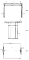
- the table 1 to be described designed as office furniture, has three lateral table legs 2 and 3 with a rhombus-shaped cross section.
- the table top 5 of the table 1 rests on a table frame 6 with two cross members 7.
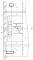
- the two table legs 2 and 3 have a cavity 8 which serves to accommodate two devices for height adjustment and fixing the table top 5. These devices are marked according to FIGS. 3 and 4 in the two table legs 2 and 3 with two crosses each. Two of these devices of a table leg 2 or 3 are held in a bearing plate 12 by means of screw spindles 13 and 14. These devices each comprise a transport plate 9, arranged in the cavity 8 of the table leg 2, and a clamping plate 10 located outside the leg 2.
- the transport plate 9 is provided with an outer-center, continuous bore 16.
- a side opening 17 in the plate 9 enables the insertion of a nut 18, which is inserted into the side opening 17 with a corresponding clearance with respect to the three-dimensional transport plate 9.
- the nut 18 has a threaded bore which serves to receive the screw spindle 14.
- the screw spindles 13 and 14 are rotatably held in the bearing plates 12, so that when they are rotated their transport plates 9 are correspondingly adjusted in height.
- the mounting of the nut 18 with a large amount of play in the side opening 17 ensures a jam-free adjustment. This adjustment is carried out effortlessly by means of an Allen key 38, without any dismantling of table parts, through corresponding openings, for example in the table top 5.
- the clamping plate 10 in turn has a passage 22 in its upper half and a bore 24 opposite the passage 21 in its lower part. This serves to receive a pin 25 which projects into the passage 21 of the transport plate 9, as shown in FIG. 5 shows. Due to the formation of the passage 21 in the transport plate 9, the clamping plate 9 can be pivoted about the pivot axis 26 by a few, e.g. 10 ° possible, so that the table top 5 can assume an inclined position in the desired frame.
- the table frame 6, on which the table top 5 is mounted is attached to bearing arms 15, which in turn are firmly connected to the device.
- the transport plate 9 and with it are adjusted in height.
- a clamping device 27 with a horizontal bearing part 28 and a vertical bearing part 29 is used. These parts serve to accommodate an angular drive 30 with a horizontally mounted driven bevel gear 31 and a vertical drive bevel gear 32.
- the bevel gear 31 points an extension in the form of a screw bolt 33, which, inserted through the passage 22, is screwed into the threaded bore 19 of the transport plate 9.
- the bevel gear 32 in turn is provided with an Allen key socket 34, by means of the Allen key 38, without dismantling the table top 5, after adjusting the height and possibly tilting the table top, by turning the bevel gear 32, the bevel gear 31 with its screw bolt 33, the tensioning device 27 to the transport plate 9 moves there.
- the inner wall of the table leg 2, 3 is sandwiched between the two plates 9 and 10, so that the table top 5 on the table frame 6, connected to the clamping device 27, is connected to the table legs 2 and 3 without play.
- the clamping plate 10 is clamped via the clamping surface 36, which is roughened like a cord, for example.
- the height adjustment and possibly inclination of the table top 5 is carried out as follows without any disassembly of parts:
- the table top 5 should be lowered and tilted. Inserted into the socket 34 by means of the Allen key 38, the bevel gear 32 and with it the bevel gear 31 are rotated such that (FIG. 5) the screw bolt 33 is extended when the transport plate 9 is stationary and the clamping plate 10 is pushed to the right. As a result, the fixation between the clamping device 27 or the table top 5 and the table leg 2 is released.
- the screw bolt 33 is screwed into the transport plate 9 by means of the Allen key 38 via the angle drive 30.
- the clamping surface 36 presses the clamping plate 10 against the inner wall of the table level 2 until the fixing between the transport plate 9, the table leg 2 and the clamping plate 10 has been carried out without play.
- a corresponding longitudinal groove is provided in the inside of the table leg 2, as can be seen in FIG. 5.
- Each table leg 2 or 3 is provided for receiving two screw spindles 13 and 14 in the bearing plate 12, so that only three legs are required for two table tops 5 lying next to one another, the two table tops 5 being able to be adjusted individually and without impairing the secondary plate.
- the table frame 6, support for the table top 5, is connected to the bearing arms 15, e.g. welded or screwed.
- the two side box profiles of the table frame 6 are of different heights. The smaller profile leaves a passage between its top wall and the table top 5, which allows the insertion of cables for lighting, telephone, computer and other electrical connections without these cables disruptively occupying the table surface of the table top 5. Corresponding laying of these cables is also ensured by the cavities 8 of the table legs 2 and 3.
Landscapes
- Tables And Desks Characterized By Structural Shape (AREA)
- Forklifts And Lifting Vehicles (AREA)
- Vehicle Cleaning, Maintenance, Repair, Refitting, And Outriggers (AREA)
- Exposure And Positioning Against Photoresist Photosensitive Materials (AREA)
- Legs For Furniture In General (AREA)
- Electrical Discharge Machining, Electrochemical Machining, And Combined Machining (AREA)
- Constitution Of High-Frequency Heating (AREA)
- Sewing Machines And Sewing (AREA)
- Electrophotography Configuration And Component (AREA)
- Accessory Devices And Overall Control Thereof (AREA)
- Exposure Or Original Feeding In Electrophotography (AREA)
Claims (13)
- Dispositif pour le réglage en hauteur et la fixation du plateau de table (5) d'une table (1), telle qu'une table de bureau ou de travail, au moyen d'un dispositif porteur (9, 10) déplaçable verticalement et apte à être bloqué, caractérisé en ce que le dispositif porteur comprend une paire d'éléments (9, 10) en forme de plaque, des moyens (13, 14 ; 33) étant prévus pour le déplacement de ces éléments, le premier élément (9) étant réglable en hauteur et le second (10) étant déplaçable transversalement au premier, en direction de celui-ci, afin de bloquer une partie fixe (2, 3) de la table (1) telle que la paroi verticale d'un pied de table (2, 3), à l'aide des moyens de déplacement, en sandwich entre les deux éléments (9, 10), et de relier ceux-ci sans jeu l'un à l'autre dans la position voulue par l'intermédiaire des moyens de déplacement.
- Dispositif selon la revendication 1, caractérisé en ce que le déplacement des éléments (9, 10) dans deux directions perpendiculaires entre elles est effectué au moyen de mouvements de rotation, en particulier au moyen de boulons filetés (13, 14 ; 33), dont l'actionnement est assuré de préférence depuis l'extérieur, par exemple à l'aide d'une clé, à partir du haut.
- Dispositif selon l'une des revendications 1 ou 2, caractérisé en ce que l'élément déplaçable transversalement (10) est déplacé à l'aide d'un engrenage (30), de préférence une commande par engrenage d'angle, en particulier un engrenage à roues coniques.
- Dispositif selon l'une quelconque des revendications 1 à 3, caractérisé en ce que les éléments (9, 10) peuvent être débloqués et pivoter l'un par rapport à l'autre.
- Dispositif selon l'une quelconque des revendications 1 à 4, caractérisé en ce que le premier élément (9) est une plaque transporteuse, et en ce que le réglage en hauteur est effectué au moyen d'une tige filetée (13, 14) accessible depuis le haut et qui est en prise avec un écrou (18) monté avec du jeu, par exemple dans l'espace, dans la plaque transporteuse (9).
- Dispositif selon l'une quelconque des revendications 1 à 5, caractérisé en ce que le premier élément (9) est pourvu d'une ouverture (21) et le second élément (10) est muni d'un téton (25) faisant saillie dans l'ouverture (21), lesquels sont dimensionnés de manière à permettre un mouvement de pivotement relatif des éléments (9, 10).
- Dispositif selon l'une quelconque des revendications 1 à 6, caractérisé en ce que dans la position non fixée, les deux éléments (9, 10) présentent un jeu mutuel sensible afin de pouvoir, lors du changement de la position du plateau (5), immobiliser celui-ci sans blocage.
- Dispositif selon l'une quelconque des revendications 1 à 7, caractérisé en ce que la fixation du plateau de table (5) est effectuée au moyen d'un excentrique.
- Meuble comportant au moins un dispositif selon l'une quelconque des revendications 1 à 8, caractérisé en ce que l'un au maximum des deux éléments (9, 10) est situé à l'intérieur (8) du pied de table (2, 3).
- Meuble (1) comportant au moins un dispositif pour le réglage en hauteur et la fixation du plateau de table (5) du meuble selon l'une quelconque des revendications 1 à 8, caractérisé en ce que le déblocage, le réglage en hauteur, le pivotement et la fixation du plateau (5) sont effectués de manière continue de l'extérieur par des mouvements de rotation.
- Meuble selon l'une des revendications 9 ou 10, caractérisé en ce qu'au moins un pied (2, 3) présente deux dispositifs.
- Meuble selon l'une quelconque des revendications 9 à 11, caractérisé en ce qu'il est prévu, entre le plateau de table (5) et le châssis de table (6) portant ce dernier, un espace libre pour la mise en place de câbles.
- Meuble selon l'une quelconque des revendications 9 à 12, caractérisé en ce que le pied (2, 3) présente une section transversale en forme de losange.
Priority Applications (1)
| Application Number | Priority Date | Filing Date | Title |
|---|---|---|---|
| AT89115544T ATE90186T1 (de) | 1988-09-02 | 1989-08-23 | Einrichtung zum hoehenverstellen und fixieren der tischplatte eines tisches. |
Applications Claiming Priority (2)
| Application Number | Priority Date | Filing Date | Title |
|---|---|---|---|
| CH329888 | 1988-09-02 | ||
| CH3298/88 | 1988-09-02 |
Publications (2)
| Publication Number | Publication Date |
|---|---|
| EP0360020A1 EP0360020A1 (fr) | 1990-03-28 |
| EP0360020B1 true EP0360020B1 (fr) | 1993-06-09 |
Family
ID=4252961
Family Applications (1)
| Application Number | Title | Priority Date | Filing Date |
|---|---|---|---|
| EP89115544A Expired - Lifetime EP0360020B1 (fr) | 1988-09-02 | 1989-08-23 | Installation de réglage en hauteur et de fixation de la surface de travail d'une table |
Country Status (10)
| Country | Link |
|---|---|
| EP (1) | EP0360020B1 (fr) |
| JP (1) | JPH02189106A (fr) |
| AT (1) | ATE90186T1 (fr) |
| AU (1) | AU4100289A (fr) |
| DE (1) | DE58904616D1 (fr) |
| DK (1) | DK433089A (fr) |
| ES (1) | ES2041915T3 (fr) |
| FI (1) | FI894057A7 (fr) |
| NO (1) | NO893440L (fr) |
| PT (1) | PT91614A (fr) |
Families Citing this family (1)
| Publication number | Priority date | Publication date | Assignee | Title |
|---|---|---|---|---|
| US8215241B2 (en) * | 2010-02-25 | 2012-07-10 | Msb Design | Vertical linear actuator mechanism |
Family Cites Families (2)
| Publication number | Priority date | Publication date | Assignee | Title |
|---|---|---|---|---|
| US4627364A (en) * | 1985-12-20 | 1986-12-09 | Lear Siegler, Inc. | Vertically-adjustable desk structure |
| DE8711298U1 (de) * | 1987-08-20 | 1987-10-01 | Schroff Gmbh, 7541 Straubenhardt | Arbeitstisch mit verstellbarer Tischplatte |
-
1989
- 1989-08-23 DE DE8989115544T patent/DE58904616D1/de not_active Expired - Fee Related
- 1989-08-23 ES ES198989115544T patent/ES2041915T3/es not_active Expired - Lifetime
- 1989-08-23 EP EP89115544A patent/EP0360020B1/fr not_active Expired - Lifetime
- 1989-08-23 AT AT89115544T patent/ATE90186T1/de not_active IP Right Cessation
- 1989-08-28 NO NO89893440A patent/NO893440L/no unknown
- 1989-08-30 FI FI894057A patent/FI894057A7/fi not_active IP Right Cessation
- 1989-08-31 AU AU41002/89A patent/AU4100289A/en not_active Abandoned
- 1989-09-01 PT PT91614A patent/PT91614A/pt not_active Application Discontinuation
- 1989-09-01 JP JP1224750A patent/JPH02189106A/ja active Pending
- 1989-09-01 DK DK433089A patent/DK433089A/da not_active Application Discontinuation
Also Published As
| Publication number | Publication date |
|---|---|
| ATE90186T1 (de) | 1993-06-15 |
| FI894057A0 (fi) | 1989-08-30 |
| JPH02189106A (ja) | 1990-07-25 |
| FI894057A7 (fi) | 1990-03-03 |
| NO893440L (no) | 1990-03-05 |
| AU4100289A (en) | 1990-03-08 |
| EP0360020A1 (fr) | 1990-03-28 |
| DK433089A (da) | 1990-03-03 |
| NO893440D0 (no) | 1989-08-28 |
| ES2041915T3 (es) | 1993-12-01 |
| DK433089D0 (da) | 1989-09-01 |
| PT91614A (pt) | 1990-03-30 |
| DE58904616D1 (de) | 1993-07-15 |
Similar Documents
| Publication | Publication Date | Title |
|---|---|---|
| DE60012314T2 (de) | Warenschaustand | |
| WO1996012423A1 (fr) | Table | |
| EP1432330A1 (fr) | Plaque orientable dotee de pieds | |
| EP0225609B1 (fr) | Charnière | |
| DE3635108A1 (de) | Bausatz fuer moebelelemente | |
| EP0360020B1 (fr) | Installation de réglage en hauteur et de fixation de la surface de travail d'une table | |
| EP0274569B1 (fr) | Bureau avec tablette supplémentaire | |
| EP0681891A1 (fr) | Table de travail et de montage | |
| DE3014489A1 (de) | Montagewagen | |
| DE3438313A1 (de) | Arbeitstisch, insbesondere buerotisch | |
| DE3036109C2 (de) | Artikulator für gnathologische Zwecke | |
| DE69626843T2 (de) | Schwenkbare trageeinrichtung und entfaltbare panele | |
| DE202004013401U1 (de) | Montageplatte zur verstellbaren Halterung von Möbelscharnieren am Korpus von Möbelstücken | |
| DE29808140U1 (de) | Schneidgerät für Schaumstoffplatten | |
| WO1986001267A1 (fr) | Systeme a bras oscillants | |
| DE19613167A1 (de) | Gerät zum Ausrichten einer Türzarge innerhalb einer Türöffnung einer Gebäudewand | |
| DE4437227C2 (de) | Bürotisch mit einem Bildschirmtablar | |
| DE102019131467B4 (de) | Arbeitstisch mit verstellbarer Fußablage sowie Montageset zur Ausrüstung eines Arbeitstisches mit einer Fußablage | |
| DE3415850A1 (de) | Tragsockel fuer ein bildschirmgeraet z.b. ein fernsehgeraet | |
| DE19642387C1 (de) | Tischfußgestell | |
| DE4000957C1 (en) | Workpiece clamping, depositing, and stop appts. - has clamping or holding addition with two bearing plates for threaded spindle | |
| WO2002094060A1 (fr) | Meuble combine | |
| DE4128277C1 (fr) | ||
| DE3918626C2 (fr) | ||
| DE29914640U1 (de) | Verstellbare Tischlampe |
Legal Events
| Date | Code | Title | Description |
|---|---|---|---|
| PUAI | Public reference made under article 153(3) epc to a published international application that has entered the european phase |
Free format text: ORIGINAL CODE: 0009012 |
|
| AK | Designated contracting states |
Kind code of ref document: A1 Designated state(s): AT BE CH DE ES FR GB GR IT LI LU NL SE |
|
| 17P | Request for examination filed |
Effective date: 19900808 |
|
| 17Q | First examination report despatched |
Effective date: 19911211 |
|
| ITF | It: translation for a ep patent filed | ||
| GRAA | (expected) grant |
Free format text: ORIGINAL CODE: 0009210 |
|
| AK | Designated contracting states |
Kind code of ref document: B1 Designated state(s): AT BE CH DE ES FR GB GR IT LI LU NL SE |
|
| PG25 | Lapsed in a contracting state [announced via postgrant information from national office to epo] |
Ref country code: GR Free format text: LAPSE BECAUSE OF FAILURE TO SUBMIT A TRANSLATION OF THE DESCRIPTION OR TO PAY THE FEE WITHIN THE PRESCRIBED TIME-LIMIT Effective date: 19930609 Ref country code: GB Effective date: 19930609 |
|
| REF | Corresponds to: |
Ref document number: 90186 Country of ref document: AT Date of ref document: 19930615 Kind code of ref document: T |
|
| PGFP | Annual fee paid to national office [announced via postgrant information from national office to epo] |
Ref country code: BE Payment date: 19930625 Year of fee payment: 5 |
|
| PGFP | Annual fee paid to national office [announced via postgrant information from national office to epo] |
Ref country code: SE Payment date: 19930713 Year of fee payment: 5 |
|
| REF | Corresponds to: |
Ref document number: 58904616 Country of ref document: DE Date of ref document: 19930715 |
|
| ET | Fr: translation filed | ||
| PGFP | Annual fee paid to national office [announced via postgrant information from national office to epo] |
Ref country code: ES Payment date: 19930805 Year of fee payment: 5 |
|
| PGFP | Annual fee paid to national office [announced via postgrant information from national office to epo] |
Ref country code: FR Payment date: 19930825 Year of fee payment: 5 |
|
| PGFP | Annual fee paid to national office [announced via postgrant information from national office to epo] |
Ref country code: AT Payment date: 19930826 Year of fee payment: 5 |
|
| PG25 | Lapsed in a contracting state [announced via postgrant information from national office to epo] |
Ref country code: LU Free format text: LAPSE BECAUSE OF NON-PAYMENT OF DUE FEES Effective date: 19930831 |
|
| PGFP | Annual fee paid to national office [announced via postgrant information from national office to epo] |
Ref country code: NL Payment date: 19930831 Year of fee payment: 5 |
|
| REG | Reference to a national code |
Ref country code: GR Ref legal event code: FG4A Free format text: 3008115 |
|
| PGFP | Annual fee paid to national office [announced via postgrant information from national office to epo] |
Ref country code: DE Payment date: 19931009 Year of fee payment: 5 |
|
| PGFP | Annual fee paid to national office [announced via postgrant information from national office to epo] |
Ref country code: CH Payment date: 19931028 Year of fee payment: 5 |
|
| REG | Reference to a national code |
Ref country code: ES Ref legal event code: FG2A Ref document number: 2041915 Country of ref document: ES Kind code of ref document: T3 |
|
| GBV | Gb: ep patent (uk) treated as always having been void in accordance with gb section 77(7)/1977 [no translation filed] |
Effective date: 19930609 |
|
| PLBE | No opposition filed within time limit |
Free format text: ORIGINAL CODE: 0009261 |
|
| STAA | Information on the status of an ep patent application or granted ep patent |
Free format text: STATUS: NO OPPOSITION FILED WITHIN TIME LIMIT |
|
| 26N | No opposition filed | ||
| PG25 | Lapsed in a contracting state [announced via postgrant information from national office to epo] |
Ref country code: AT Effective date: 19940823 |
|
| PG25 | Lapsed in a contracting state [announced via postgrant information from national office to epo] |
Ref country code: SE Effective date: 19940824 Ref country code: ES Free format text: LAPSE BECAUSE OF THE APPLICANT RENOUNCES Effective date: 19940824 |
|
| PG25 | Lapsed in a contracting state [announced via postgrant information from national office to epo] |
Ref country code: LI Effective date: 19940831 Ref country code: CH Effective date: 19940831 Ref country code: BE Effective date: 19940831 |
|
| REG | Reference to a national code |
Ref country code: GR Ref legal event code: MM2A Free format text: 3008115 |
|
| EAL | Se: european patent in force in sweden |
Ref document number: 89115544.2 |
|
| BERE | Be: lapsed |
Owner name: STILO A.G. Effective date: 19940831 |
|
| PG25 | Lapsed in a contracting state [announced via postgrant information from national office to epo] |
Ref country code: NL Effective date: 19950301 |
|
| NLV4 | Nl: lapsed or anulled due to non-payment of the annual fee | ||
| PG25 | Lapsed in a contracting state [announced via postgrant information from national office to epo] |
Ref country code: FR Effective date: 19950428 |
|
| REG | Reference to a national code |
Ref country code: CH Ref legal event code: PL |
|
| PG25 | Lapsed in a contracting state [announced via postgrant information from national office to epo] |
Ref country code: DE Effective date: 19950503 |
|
| EUG | Se: european patent has lapsed |
Ref document number: 89115544.2 |
|
| REG | Reference to a national code |
Ref country code: FR Ref legal event code: ST |
|
| REG | Reference to a national code |
Ref country code: ES Ref legal event code: FD2A Effective date: 19991007 |
|
| PG25 | Lapsed in a contracting state [announced via postgrant information from national office to epo] |
Ref country code: IT Free format text: LAPSE BECAUSE OF NON-PAYMENT OF DUE FEES;WARNING: LAPSES OF ITALIAN PATENTS WITH EFFECTIVE DATE BEFORE 2007 MAY HAVE OCCURRED AT ANY TIME BEFORE 2007. THE CORRECT EFFECTIVE DATE MAY BE DIFFERENT FROM THE ONE RECORDED. Effective date: 20050823 |