EP0360090A1 - Chaudière à gaz avec brûleur atmosphérique - Google Patents
Chaudière à gaz avec brûleur atmosphérique Download PDFInfo
- Publication number
- EP0360090A1 EP0360090A1 EP89116600A EP89116600A EP0360090A1 EP 0360090 A1 EP0360090 A1 EP 0360090A1 EP 89116600 A EP89116600 A EP 89116600A EP 89116600 A EP89116600 A EP 89116600A EP 0360090 A1 EP0360090 A1 EP 0360090A1
- Authority
- EP
- European Patent Office
- Prior art keywords
- gas
- insert
- burner
- shell
- displacer
- Prior art date
- Legal status (The legal status is an assumption and is not a legal conclusion. Google has not performed a legal analysis and makes no representation as to the accuracy of the status listed.)
- Granted
Links
- 238000002485 combustion reaction Methods 0.000 claims abstract description 21
- 238000012546 transfer Methods 0.000 claims abstract description 14
- 238000006073 displacement reaction Methods 0.000 claims description 14
- 238000010438 heat treatment Methods 0.000 claims description 6
- 230000002093 peripheral effect Effects 0.000 claims description 6
- 239000007789 gas Substances 0.000 abstract description 26
- 238000005266 casting Methods 0.000 abstract description 5
- 239000002912 waste gas Substances 0.000 abstract 2
- 239000003110 molding sand Substances 0.000 description 5
- 238000004519 manufacturing process Methods 0.000 description 4
- 229910001018 Cast iron Inorganic materials 0.000 description 2
- 230000015572 biosynthetic process Effects 0.000 description 2
- 238000001816 cooling Methods 0.000 description 2
- 238000013461 design Methods 0.000 description 2
- 238000011161 development Methods 0.000 description 2
- 230000018109 developmental process Effects 0.000 description 2
- 230000000694 effects Effects 0.000 description 2
- 239000000463 material Substances 0.000 description 2
- 238000000465 moulding Methods 0.000 description 2
- 238000007493 shaping process Methods 0.000 description 2
- 239000011230 binding agent Substances 0.000 description 1
- 150000001875 compounds Chemical class 0.000 description 1
- 238000003780 insertion Methods 0.000 description 1
- 230000037431 insertion Effects 0.000 description 1
- 238000009434 installation Methods 0.000 description 1
- 230000010354 integration Effects 0.000 description 1
- 239000002184 metal Substances 0.000 description 1
- 229910052751 metal Inorganic materials 0.000 description 1
- 230000000630 rising effect Effects 0.000 description 1
- 239000000565 sealant Substances 0.000 description 1
- 238000007789 sealing Methods 0.000 description 1
- 231100000331 toxic Toxicity 0.000 description 1
- 230000002588 toxic effect Effects 0.000 description 1
Images


Classifications
-
- F—MECHANICAL ENGINEERING; LIGHTING; HEATING; WEAPONS; BLASTING
- F24—HEATING; RANGES; VENTILATING
- F24H—FLUID HEATERS, e.g. WATER OR AIR HEATERS, HAVING HEAT-GENERATING MEANS, e.g. HEAT PUMPS, IN GENERAL
- F24H1/00—Water heaters, e.g. boilers, continuous-flow heaters or water-storage heaters
- F24H1/22—Water heaters other than continuous-flow or water-storage heaters, e.g. water heaters for central heating
- F24H1/24—Water heaters other than continuous-flow or water-storage heaters, e.g. water heaters for central heating with water mantle surrounding the combustion chamber or chambers
- F24H1/26—Water heaters other than continuous-flow or water-storage heaters, e.g. water heaters for central heating with water mantle surrounding the combustion chamber or chambers the water mantle forming an integral body
- F24H1/28—Water heaters other than continuous-flow or water-storage heaters, e.g. water heaters for central heating with water mantle surrounding the combustion chamber or chambers the water mantle forming an integral body including one or more furnace or fire tubes
-
- F—MECHANICAL ENGINEERING; LIGHTING; HEATING; WEAPONS; BLASTING
- F24—HEATING; RANGES; VENTILATING
- F24H—FLUID HEATERS, e.g. WATER OR AIR HEATERS, HAVING HEAT-GENERATING MEANS, e.g. HEAT PUMPS, IN GENERAL
- F24H2230/00—Solid fuel fired boiler
Definitions
- the invention relates to a gas boiler with an atmospheric burner according to the preamble of the main claim.
- a gas boiler of this type is known from FR-A-20 86 966. Furthermore, a relevant gas boiler according to DE-U-80 02 621 is known. A gas boiler according to DE-A-22 89 019 has a similar structure.
- the displacer body of the boiler according to DE-U-80 02 621 is a kind of pot-shaped combustion chamber which, with its open end, faces the atmospheric gas burner arranged underneath is directed. The heat transfer to the heat transfer medium can therefore only take place via the ribbed shaft walls, and since this displacer insert cannot be cooled and thus becomes very hot, this displacer can also have a non-NOX-reducing effect on the combustion process.
- a water-carrying sheet metal cylinder is used in the burner shaft, occupying practically its entire height, which is connected to the water-carrying double wall of the burner shaft with supply and return connections.
- the outer wall of the cylinder is covered with longitudinal ribs formed and attached from special profiles.
- This cylindrical displacement insert is particularly thermally highly stressed on the inflow side and is therefore also inevitably exposed to condensate attacks, whereby, as far as heat transfer is concerned, an imbalance between the non-finned, water-cooled combustion chamber on the one hand and the externally finned, water-cooled displacement insert on the other consists.
- FR-A-20 86 966 does not show how the displacement insert is actually designed to be able to meet all heating requirements, namely a sufficiently long burnout distance, condensate resistance, NOX reduction with the largest possible heat transfer area and still simple production.
- the invention is therefore based on the object of improving a gas boiler of the generic type in such a way that, in the case of condensate-resistant design of its hot gas-charged areas, the central shaft area within the fins also, as in the case of the boiler according to FR-A-20 86 966, for heat transfer to the heat transfer medium can be used with the proviso that these elements involved in their manufacture and assembly can be made condensate-proof in a simple manner and at the same time have a NOX-reducing effect on the combustion process, the production of the displacement insert also taking into account environmentally friendly aspects.
- the principle of a water-carrying displacement insert is therefore not simple, which would be obvious, in such a way that the displacement insert according to FR-A-20 86 966 is replaced by one made of cast iron, but this displacement insert is made of two liquid-tight materials joinable shells formed, which are "green shaped” formed of condensate-resistant cast. “Green-shaped” is understood to mean that the casting can be formed without a core, ie the positive model of the two shells is designed in such a way that it can be removed from the molding sand and no cores of molding sand are arranged between the two molding sand parts Need to become.
- the entire displacement insert is therefore very easy to produce by casting, which can be kept considerably shorter or smaller than the displacement insert according to FR-A-20 86 due to the fact that the combustion chamber wall should also be provided with longitudinal ribs 966.
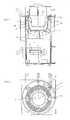
- the gas boiler consists of a cylindrical, water-cooled burner shaft 1, in the lowest area of which the atmospheric gas burner 2 and, via this, a displacer insert 4, which is circular in cross-section and is delimited by ribbing and is delimited by ribbing, is connected to the water-cooled burner shaft 1 and above it there is an exhaust gas collection chamber 5 with a central exhaust gas outlet connection.
- the displacer insert 4 is formed from two shells 6, 7 which can be joined together in a liquid-tight manner and which are “green-shaped” and are formed from condensate-resistant cast.
- the lower, burner-side shell 6 has a sprue extension 8 for connecting the inflow channel 9, which connects the displacement insert 4 with the water-carrying double jacket of the combustion shaft 1.
- two or three inflow channels 9, correspondingly distributed over the circumference, can also be provided. In the embodiment shown in FIG.
- the upper shell 7 is formed as a pot 7 'and this is inserted into the likewise cup-shaped lower shell 6, the peripheral edge 20 of the upper shell 7' being placed on the peripheral edge 21 of the lower shell in a sealed manner
- Case is provided both with the connection extension 8 for the lower inflow channel 9 and for the upper outflow channel 10.
- both the lower shell 6 is provided with radially outwardly directed longitudinal ribs 12 and the combustion chamber wall 14 is provided with radially inwardly directed longitudinal ribs 15, the ribs 12 engaging in the spaces between the ribs 15.
- the lower shells 6 in all of the exemplary embodiments are provided with cast-on heat transfer surface enlargements 11 in the form of knobs 17 on their bottom wall 16, which can easily be taken into account in the production of the lower shell 6, since this makes the molding from casting material readily and allows without much effort.
- the gas boiler is designed such that the upper shell 7, which is designed as a pot and is inserted into the lower shell 6, has a circumferential edge 21 which bulges back in the direction of its base 16, and the connecting extension 8 for the upper outflow channel 10 has.
- the curved peripheral edge 21 also has radially outwardly directed longitudinal ribs 12 '.
- the upper shell 7 is also provided with radially outwardly directed longitudinal ribs 12.
- the upper shell 7 is, as shown, designed as an arch 18 over the opening 18 of the lower, cup-shaped shell 6, which is provided with an outflow region 19 rising to the outflow channel connection 10.
- Such a shaping can also be carried out without a core, with only the hole for the connection of the upper overflow channel 10 having to be drilled out.
- the connection extension 8 on the lower shell 6 points downwards and the overflow channel 9 is connected very deeply, as can be seen, to the water-carrying double wall of the combustion shaft 1.
- the two shells 6, 7 are connected to one another at their connecting edges 22, which of course have to be machined accordingly, with screws 23, including an annular seal 24.
- FIG. 6 it is also possible, and this also applies to the embodiment of FIG. 7, to provide the connecting edges 22 of the two shells 6, 7 with internal and external threads 25 and to screw the two shells together in a sealed manner.
- the installation in the combustion shaft 1 takes place, of course, in the screwed-together state of the displacer body 4.
- the displacer body 4 has a pot-like upper bowl 7 projecting into the interior of the lower bowl 6, as is the case with the exemplary embodiments according to FIGS.
- the combustion shaft wall 14 is double-walled, that is, according to the exemplary embodiment, the combustion shaft wall is formed from individual cast rings 14 ', on which the radially inward directed longitudinal ribs 15 are cast with.
- the inflow and outflow ducts 9, 10, like the combustion shaft wall 14 are double-walled.
- the inner channel piece is sealed and screwed into the molded-on connection extension 8 of the displacement insert 4, the outer channel piece 28 then simply being pushed over the opening 27 in the combustion shaft wall 14.
Landscapes
- Engineering & Computer Science (AREA)
- Physics & Mathematics (AREA)
- Thermal Sciences (AREA)
- Chemical & Material Sciences (AREA)
- Combustion & Propulsion (AREA)
- Mechanical Engineering (AREA)
- General Engineering & Computer Science (AREA)
- Devices For Medical Bathing And Washing (AREA)
- Incineration Of Waste (AREA)
- Molds, Cores, And Manufacturing Methods Thereof (AREA)
- Heat-Exchange Devices With Radiators And Conduit Assemblies (AREA)
Priority Applications (1)
| Application Number | Priority Date | Filing Date | Title |
|---|---|---|---|
| AT89116600T ATE83552T1 (de) | 1988-09-14 | 1989-09-08 | Gasheizkessel mit atmosphaerischem brenner. |
Applications Claiming Priority (2)
| Application Number | Priority Date | Filing Date | Title |
|---|---|---|---|
| DE3831237 | 1988-09-14 | ||
| DE3831237A DE3831237A1 (de) | 1988-09-14 | 1988-09-14 | Gasheizkessel mit atmosphaerischem brenner |
Publications (2)
| Publication Number | Publication Date |
|---|---|
| EP0360090A1 true EP0360090A1 (fr) | 1990-03-28 |
| EP0360090B1 EP0360090B1 (fr) | 1992-12-16 |
Family
ID=6362936
Family Applications (1)
| Application Number | Title | Priority Date | Filing Date |
|---|---|---|---|
| EP89116600A Expired - Lifetime EP0360090B1 (fr) | 1988-09-14 | 1989-09-08 | Chaudière à gaz avec brûleur atmosphérique |
Country Status (4)
| Country | Link |
|---|---|
| EP (1) | EP0360090B1 (fr) |
| AT (1) | ATE83552T1 (fr) |
| DE (2) | DE3831237A1 (fr) |
| ES (1) | ES2037359T3 (fr) |
Families Citing this family (1)
| Publication number | Priority date | Publication date | Assignee | Title |
|---|---|---|---|---|
| AT411492B (de) * | 1999-01-19 | 2004-01-26 | Vaillant Gmbh | Anordnung mit einem wandheizgerät |
Citations (1)
| Publication number | Priority date | Publication date | Assignee | Title |
|---|---|---|---|---|
| DE8420869U1 (de) * | 1984-07-12 | 1987-07-23 | Vießmann, Hans, Dr.h.c., 3559 Battenberg | Heizungskessel für flüssige und gasförmige Brennstoffe |
Family Cites Families (4)
| Publication number | Priority date | Publication date | Assignee | Title |
|---|---|---|---|---|
| DE451368C (de) * | 1927-10-25 | Vosswerke Akt Ges | Dampfbadkochkessel | |
| FR2086966A5 (fr) * | 1970-04-15 | 1971-12-31 | Vidalenq Maurice | |
| DE8002621U1 (de) * | 1980-02-01 | 1982-01-14 | Vießmann, Hans, 3559 Battenberg | Heizungskessel mit atmosphaerischem gasbrenner |
| DE3425667A1 (de) * | 1984-07-12 | 1986-01-23 | Hans Dr.h.c. 3559 Battenberg Vießmann | Heizungskessel fuer fluessige und gasfoermige brennstoffe |
-
1988
- 1988-09-14 DE DE3831237A patent/DE3831237A1/de not_active Withdrawn
-
1989
- 1989-09-08 EP EP89116600A patent/EP0360090B1/fr not_active Expired - Lifetime
- 1989-09-08 AT AT89116600T patent/ATE83552T1/de not_active IP Right Cessation
- 1989-09-08 ES ES198989116600T patent/ES2037359T3/es not_active Expired - Lifetime
- 1989-09-08 DE DE8989116600T patent/DE58903021D1/de not_active Expired - Fee Related
Patent Citations (1)
| Publication number | Priority date | Publication date | Assignee | Title |
|---|---|---|---|---|
| DE8420869U1 (de) * | 1984-07-12 | 1987-07-23 | Vießmann, Hans, Dr.h.c., 3559 Battenberg | Heizungskessel für flüssige und gasförmige Brennstoffe |
Also Published As
| Publication number | Publication date |
|---|---|
| EP0360090B1 (fr) | 1992-12-16 |
| ES2037359T3 (es) | 1993-06-16 |
| ATE83552T1 (de) | 1993-01-15 |
| DE58903021D1 (de) | 1993-01-28 |
| DE3831237A1 (de) | 1990-03-22 |
Similar Documents
| Publication | Publication Date | Title |
|---|---|---|
| DE3332200C2 (fr) | ||
| EP0451234B1 (fr) | Chaudiere pour combustibles liquides ou gazeux | |
| DE3807189A1 (de) | Heizgeraet, insbesondere fahrzeugzusatzheizgeraet | |
| EP0360090B1 (fr) | Chaudière à gaz avec brûleur atmosphérique | |
| EP0994313B1 (fr) | Procédé pour fabriquer un échangeur de chaleur et échangeur de chaleur produit par ce procédé | |
| DE2906362C2 (de) | Heizungskessel für flüssige oder gasförmige Brennstoffe | |
| DE69903771T2 (de) | Heizkörper für einen gas- oder ölbeheizten kessel und module zur herstellung davon | |
| EP0414925B1 (fr) | Chaudière pour brûler des combustibles fluides ou gazeux | |
| EP0680586A1 (fr) | Chaudiere de chauffage | |
| EP0387627B1 (fr) | Chaudière | |
| AT281353B (de) | Kachelofen-einsatz | |
| EP0209703B1 (fr) | Cartouche incandescente pour fours, en particulier pour chaudières ainsi que four avec une telle cartouche | |
| AT386676B (de) | Heizkessel | |
| AT395649B (de) | Kaminkopf fuer luft-abgas-kamine | |
| AT406705B (de) | Endabschnitt für rohre, stutzen od.dgl. | |
| DE8707499U1 (de) | Heizungskessel | |
| DE3108452C2 (de) | Öl/Gas-Heizkessel | |
| DE3425667A1 (de) | Heizungskessel fuer fluessige und gasfoermige brennstoffe | |
| DE9418056U1 (de) | Luft/Abgas-Schornstein | |
| EP0430061B1 (fr) | Chaudière de chauffage | |
| DE703278C (de) | Gliederheizkoerper, besonders fuer Kraftfahrzeuge | |
| EP0217320A2 (fr) | Chaudière pour combustibles liquides ou gazéiformes | |
| DE705026C (de) | Herd- und Ofensparplatte | |
| EP0563589A1 (fr) | Chaudière | |
| AT397553B (de) | Heizkessel für feste brennstoffe |
Legal Events
| Date | Code | Title | Description |
|---|---|---|---|
| PUAI | Public reference made under article 153(3) epc to a published international application that has entered the european phase |
Free format text: ORIGINAL CODE: 0009012 |
|
| AK | Designated contracting states |
Kind code of ref document: A1 Designated state(s): AT BE CH DE ES FR GB IT LI LU |
|
| 17P | Request for examination filed |
Effective date: 19900317 |
|
| 17Q | First examination report despatched |
Effective date: 19910115 |
|
| GRAA | (expected) grant |
Free format text: ORIGINAL CODE: 0009210 |
|
| AK | Designated contracting states |
Kind code of ref document: B1 Designated state(s): AT BE CH DE ES FR GB IT LI LU |
|
| REF | Corresponds to: |
Ref document number: 83552 Country of ref document: AT Date of ref document: 19930115 Kind code of ref document: T |
|
| ET | Fr: translation filed | ||
| REF | Corresponds to: |
Ref document number: 58903021 Country of ref document: DE Date of ref document: 19930128 |
|
| ITF | It: translation for a ep patent filed | ||
| GBT | Gb: translation of ep patent filed (gb section 77(6)(a)/1977) |
Effective date: 19930426 |
|
| REG | Reference to a national code |
Ref country code: ES Ref legal event code: FG2A Ref document number: 2037359 Country of ref document: ES Kind code of ref document: T3 |
|
| PLBE | No opposition filed within time limit |
Free format text: ORIGINAL CODE: 0009261 |
|
| STAA | Information on the status of an ep patent application or granted ep patent |
Free format text: STATUS: NO OPPOSITION FILED WITHIN TIME LIMIT |
|
| 26N | No opposition filed | ||
| EPTA | Lu: last paid annual fee | ||
| PGFP | Annual fee paid to national office [announced via postgrant information from national office to epo] |
Ref country code: LU Payment date: 19960801 Year of fee payment: 8 |
|
| PGFP | Annual fee paid to national office [announced via postgrant information from national office to epo] |
Ref country code: BE Payment date: 19960830 Year of fee payment: 8 |
|
| PGFP | Annual fee paid to national office [announced via postgrant information from national office to epo] |
Ref country code: GB Payment date: 19960906 Year of fee payment: 8 |
|
| PGFP | Annual fee paid to national office [announced via postgrant information from national office to epo] |
Ref country code: ES Payment date: 19960910 Year of fee payment: 8 |
|
| PGFP | Annual fee paid to national office [announced via postgrant information from national office to epo] |
Ref country code: CH Payment date: 19960920 Year of fee payment: 8 |
|
| PGFP | Annual fee paid to national office [announced via postgrant information from national office to epo] |
Ref country code: FR Payment date: 19960927 Year of fee payment: 8 |
|
| PGFP | Annual fee paid to national office [announced via postgrant information from national office to epo] |
Ref country code: AT Payment date: 19960930 Year of fee payment: 8 |
|
| PG25 | Lapsed in a contracting state [announced via postgrant information from national office to epo] |
Ref country code: LU Free format text: LAPSE BECAUSE OF NON-PAYMENT OF DUE FEES Effective date: 19970908 Ref country code: GB Free format text: LAPSE BECAUSE OF NON-PAYMENT OF DUE FEES Effective date: 19970908 Ref country code: AT Free format text: LAPSE BECAUSE OF NON-PAYMENT OF DUE FEES Effective date: 19970908 |
|
| PG25 | Lapsed in a contracting state [announced via postgrant information from national office to epo] |
Ref country code: ES Free format text: LAPSE BECAUSE OF EXPIRATION OF PROTECTION Effective date: 19970910 |
|
| PG25 | Lapsed in a contracting state [announced via postgrant information from national office to epo] |
Ref country code: LI Free format text: LAPSE BECAUSE OF NON-PAYMENT OF DUE FEES Effective date: 19970930 Ref country code: FR Free format text: THE PATENT HAS BEEN ANNULLED BY A DECISION OF A NATIONAL AUTHORITY Effective date: 19970930 Ref country code: CH Free format text: LAPSE BECAUSE OF NON-PAYMENT OF DUE FEES Effective date: 19970930 Ref country code: BE Free format text: LAPSE BECAUSE OF NON-PAYMENT OF DUE FEES Effective date: 19970930 |
|
| BERE | Be: lapsed |
Owner name: VIESSMANN HANS Effective date: 19970930 |
|
| GBPC | Gb: european patent ceased through non-payment of renewal fee |
Effective date: 19970908 |
|
| REG | Reference to a national code |
Ref country code: CH Ref legal event code: PL |
|
| REG | Reference to a national code |
Ref country code: FR Ref legal event code: ST |
|
| PGFP | Annual fee paid to national office [announced via postgrant information from national office to epo] |
Ref country code: DE Payment date: 19990924 Year of fee payment: 11 |
|
| REG | Reference to a national code |
Ref country code: ES Ref legal event code: FD2A Effective date: 20010201 |
|
| PG25 | Lapsed in a contracting state [announced via postgrant information from national office to epo] |
Ref country code: DE Free format text: LAPSE BECAUSE OF NON-PAYMENT OF DUE FEES Effective date: 20010601 |
|
| PG25 | Lapsed in a contracting state [announced via postgrant information from national office to epo] |
Ref country code: IT Free format text: LAPSE BECAUSE OF NON-PAYMENT OF DUE FEES;WARNING: LAPSES OF ITALIAN PATENTS WITH EFFECTIVE DATE BEFORE 2007 MAY HAVE OCCURRED AT ANY TIME BEFORE 2007. THE CORRECT EFFECTIVE DATE MAY BE DIFFERENT FROM THE ONE RECORDED. Effective date: 20050908 |