EP0360123A2 - Unité de stockage de données à très grande capacité - Google Patents
Unité de stockage de données à très grande capacité Download PDFInfo
- Publication number
- EP0360123A2 EP0360123A2 EP89116786A EP89116786A EP0360123A2 EP 0360123 A2 EP0360123 A2 EP 0360123A2 EP 89116786 A EP89116786 A EP 89116786A EP 89116786 A EP89116786 A EP 89116786A EP 0360123 A2 EP0360123 A2 EP 0360123A2
- Authority
- EP
- European Patent Office
- Prior art keywords
- data
- access
- recording surface
- record
- representative
- Prior art date
- Legal status (The legal status is an assumption and is not a legal conclusion. Google has not performed a legal analysis and makes no representation as to the accuracy of the status listed.)
- Withdrawn
Links
Images


Classifications
-
- G—PHYSICS
- G11—INFORMATION STORAGE
- G11B—INFORMATION STORAGE BASED ON RELATIVE MOVEMENT BETWEEN RECORD CARRIER AND TRANSDUCER
- G11B19/00—Driving, starting, stopping record carriers not specifically of filamentary or web form, or of supports therefor; Control thereof; Control of operating function ; Driving both disc and head
- G11B19/20—Driving; Starting; Stopping; Control thereof
-
- G—PHYSICS
- G06—COMPUTING OR CALCULATING; COUNTING
- G06F—ELECTRIC DIGITAL DATA PROCESSING
- G06F3/00—Input arrangements for transferring data to be processed into a form capable of being handled by the computer; Output arrangements for transferring data from processing unit to output unit, e.g. interface arrangements
- G06F3/06—Digital input from, or digital output to, record carriers, e.g. RAID, emulated record carriers or networked record carriers
- G06F3/0601—Interfaces specially adapted for storage systems
-
- G—PHYSICS
- G11—INFORMATION STORAGE
- G11B—INFORMATION STORAGE BASED ON RELATIVE MOVEMENT BETWEEN RECORD CARRIER AND TRANSDUCER
- G11B21/00—Head arrangements not specific to the method of recording or reproducing
-
- G—PHYSICS
- G11—INFORMATION STORAGE
- G11B—INFORMATION STORAGE BASED ON RELATIVE MOVEMENT BETWEEN RECORD CARRIER AND TRANSDUCER
- G11B27/00—Editing; Indexing; Addressing; Timing or synchronising; Monitoring; Measuring tape travel
- G11B27/10—Indexing; Addressing; Timing or synchronising; Measuring tape travel
- G11B27/102—Programmed access in sequence to addressed parts of tracks of operating record carriers
- G11B27/105—Programmed access in sequence to addressed parts of tracks of operating record carriers of operating discs
-
- G—PHYSICS
- G11—INFORMATION STORAGE
- G11B—INFORMATION STORAGE BASED ON RELATIVE MOVEMENT BETWEEN RECORD CARRIER AND TRANSDUCER
- G11B5/00—Recording by magnetisation or demagnetisation of a record carrier; Reproducing by magnetic means; Record carriers therefor
- G11B5/48—Disposition or mounting of heads or head supports relative to record carriers ; arrangements of heads, e.g. for scanning the record carrier to increase the relative speed
- G11B5/54—Disposition or mounting of heads or head supports relative to record carriers ; arrangements of heads, e.g. for scanning the record carrier to increase the relative speed with provision for moving the head into or out of its operative position or across tracks
- G11B5/55—Track change, selection or acquisition by displacement of the head
- G11B5/5521—Track change, selection or acquisition by displacement of the head across disk tracks
- G11B5/5569—Track change, selection or acquisition by displacement of the head across disk tracks details of specially adapted mobile parts, e.g. electromechanical control devices
- G11B5/5578—Multiple actuators addressing the same disk, e.g. to improve data rate or access rate
-
- G—PHYSICS
- G06—COMPUTING OR CALCULATING; COUNTING
- G06F—ELECTRIC DIGITAL DATA PROCESSING
- G06F3/00—Input arrangements for transferring data to be processed into a form capable of being handled by the computer; Output arrangements for transferring data from processing unit to output unit, e.g. interface arrangements
- G06F3/06—Digital input from, or digital output to, record carriers, e.g. RAID, emulated record carriers or networked record carriers
- G06F3/0601—Interfaces specially adapted for storage systems
- G06F3/0668—Interfaces specially adapted for storage systems adopting a particular infrastructure
- G06F3/0671—In-line storage system
- G06F3/0673—Single storage device
-
- G—PHYSICS
- G11—INFORMATION STORAGE
- G11B—INFORMATION STORAGE BASED ON RELATIVE MOVEMENT BETWEEN RECORD CARRIER AND TRANSDUCER
- G11B2220/00—Record carriers by type
- G11B2220/20—Disc-shaped record carriers
-
- G—PHYSICS
- G11—INFORMATION STORAGE
- G11B—INFORMATION STORAGE BASED ON RELATIVE MOVEMENT BETWEEN RECORD CARRIER AND TRANSDUCER
- G11B2220/00—Record carriers by type
- G11B2220/40—Combinations of multiple record carriers
- G11B2220/41—Flat as opposed to hierarchical combination, e.g. library of tapes or discs, CD changer, or groups of record carriers that together store one title
-
- G—PHYSICS
- G11—INFORMATION STORAGE
- G11B—INFORMATION STORAGE BASED ON RELATIVE MOVEMENT BETWEEN RECORD CARRIER AND TRANSDUCER
- G11B27/00—Editing; Indexing; Addressing; Timing or synchronising; Monitoring; Measuring tape travel
- G11B27/36—Monitoring, i.e. supervising the progress of recording or reproducing
Definitions
- the present invention relates to a high-density and large-capacity storage drive and, more particularly, to a storage drive capable of permitting fast writes or reads. Fast writes and reads are permitted even where the storage drive is simultaneously accessed by a plurality of users.
- Storage drives of the prior art have typically had low recording densities which have rendered large capacities difficult to realize, even in such cases where high speed access is possible, such as in magnetic disk drives.
- storage drives using magnetic tapes or optical disks arrayed in a "juke box" form provide high capacity, but have a low throughput given their extremely slow access periods.
- Earlier technology therefore renders it difficult to allow for concurrent access to a mass storage medium from a plurality of terminals.
- the subject invention solves the above referred problems, and others, and provides a single medium mass-storage system which is capable of providing fast and efficient access to mass storage by a plurality of users.
- each surface of plurality of optical disk surfaces there are provided, on each surface of plurality of optical disk surfaces, either at least one writing and readout head, and at least one readout head or at least two writing and readout heads, which are controlled independently or simultaneously.
- frequently accessed data on the recording surfaces is relocated to a recording surface which is accessed less frequently.
- a writing and readout head or a readout head capable of moving between recording surface.
- data access is simultaneously provided to at least two recording surfaces.
- An advantage of the present invention is the provision of an inexpensive data storage drive which has a super large capacity but can be accessed at a high speed simultaneously and instantly from a plurality of terminals.
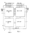
- Fig. 1 is a diagram showing the structure of a super-large capacity data storage drive according to the present invention.
- a common spindle 1 there are fixed eight disks of a dual-sided or dual surfaced recording media 2, which are rotated by a motor 3.
- an optical head 4 For each recording surface, there is provided an optical head 4, and a target address which is accessed by an access device 5.
- Data input and output are supervised by an input/output control unit 6.
- a numbering representation has been utilized which is as follows: [reference no.] - [recording surface no.] - [head in the surface]
- the super-large capacity data storage drive of the subject system is suitably connected with a CPU 7 through channels 8, as shown in Fig. 1.
- the present storage drive is accessed by the user from the CPU 7 or through the channels 8, terminal control equipment 9 and terminals 10.
- the storage drive may also be accessed from another CPU 14 through a network 12 and communication control processors 11 and 13.
- the CPU is naturally connected through channels 15 and a terminal control equipment 16 with terminals 17.
- the decline of throughput due to busy channels can be prevented if the channels 8 are increased to provide a plurality of paths.
- these channel paths are usually selected by the dynamic control method.
- the present invention provides the super-large capacity data storage drive which are so connected with the plural terminals that it can handle the access requirements of many users simultaneously.
- Fig. 2 shows one example in which one recording surface is equipped with two optical heads. Since readout frequency is generally higher than the writing frequency, the structure can be made at a reduced cost by incorporating two read/write heads read-only head.
- the optical heads are suitably arranged such that optical heads 4-1-1 and 4-1-2, which can be independently accessed by the access devices 5-1-1 and 5-1-2, are opposed to one another on a recording surface 2-1 of the recording medium 2.
- the optical heads 4-2-1 and 4-2-2 which are independently accessed by the access devices 5-2-1 and 5-2-2, are likewise arranged to oppose one another.
- each of the recording surfaces is equipped with two or more optical heads. Throughput may be further improved by utilizing greater numbers of recording surfaces and optical heads per surface, as has been described above.
- the present embodiment is exemplified as having thirty two optical heads given that each of sixteen recording surfaces is equipped with one read/write head and one readout head, which are driven independently of one another.
- the recording medium 2 is exemplified by a dual-side recording phase change optical disk.
- the recording file to be used is exemplified by a phase change recording film suitably made of In-Se-Tl-Co which will crystallize for 100 ns or less, as disclosed in Japanese Journal of Applied Physics (J.J.A.P.), Vol. 26, pp. 67, (1987) Suppl. 26-4.
- Data is written by changing the intensity of a coherent optical beam over a time between an intermediate level for crystallization, and a high level for non-crystallization, in accordance with encoded information, and by changing a phase state of the phase change recording film into a crystalline or non-crystalline state.
- the refractive index is changed with the optical path of the effect of multiple interface and the reflectivity of the recording film.
- Data reads are accomplished by illuminating the recording film with an optical beam so weak as to cause no phase change, and by the amount of the light reflected from the recording film by means of the optical head 4.
- the recording medium 2 is exemplified by the phase change recording film in the present embodiment but may be replaced by a magneto-optic recording film represented by Tb-Fe-Co. If the recording medium 2 is used as a data base requiring no data rewrites, on the other hand, it may be exemplified by either a perforated recording film, such as is disclosed in Japanese Patent Publication No. 59 19836 or a ROM disk such as a video disk.
- a tracking guide mark may be exemplified by a pre-groove or a known pre-wobbled mark.
- the guide groove may be written by the read/write head after the disk has been fixed.
- the header may be formed in advance with the mark but is desirably formatted by the read/write head after the disk has been fixed.
- the optical head 4 has substantially the same structure as that of a head of a write-once-read-many (“WORM”) optical disk now commercially available. Accordingly a dedicated description thereto will be omitted.
- WORM write-once-read-many
- the present optical head 4 is made movable within a range from the innermost to outermost tracks to perform a coarse access by the access device 5, which access device has a linear motor. However, this access device 5 may be driven by a rotary motor.
- the tracking method is accomplished like the WORM optical disk drive, for example, by a two-step control to control the slow tracking by the access device, 5 and the fast tracking by an actuator in the optical head.
- the data transfer rate is improved if the optical head 4 is exemplified by the parallel read/write optical head using a semiconductor laser array, as disclosed in Japanese Patent Application No. 62 - 173930.
- the optical head can be made light to shorten the access time if a semiconductor laser and a signal detecting optical system are stationary whereas the optical system consisted of objective lens is movable, as disclosed in 0 Plus E, Vol 67, pp. 8 (March, 1986).
- the optical head can be made thin and light if it uses the optical fibers, as disclosed in Japanese Patent Application No. 62 - 249938.
- the input/output control unit 6 includes, as shown in Fig. 3, an input/output supervision unit 18, a buffer unit 19, an access control unit 22, and a data input/output unit 25.
- the input/output supervision unit 18 first accesses a directory in the buffer unit 19 on the basis of data accessed through the channel 8.
- the supervision unit 18 extracts the data, if any, from the buffer unit 19, and otherwise accesses the disk-shaped recording medium 2.
- the buffer unit 19 function similarly to existing semiconductor cache memories. However, the buffer unit 19 is stored with the directory.
- the input/output supervision unit 18 issues an access command to the access control unit 22 to move the optical head based on the physical address on the disk stored with the data.
- the access control unit 22 accomplishes the head drive control to the recording address expressed by the recording surface, track or sector, the auto-focusing and the auto-tracking.
- the data input/output unit 25 functions primarily to modulate and demodulate, and to correct and save data.
- One access device 5 is provided for each of the optical heads so as to drive each of them independently. Since, however, all the optical heads are not always operating, the numbers of the circuits of the access control unit 22 and the data input/output unit 25 may be less than that of the optical heads. Then, a switch control unit 20 and switches 21, 23, 24 and 26 select the circuits of the access control unit and the data input/output unit. On the other hand, the circuits in the access control unit 22 and data input/output unit 25 have a one-to-one correspondence so that the switches 21, 23, 24 and 26 are associated with one another.
- the present embodiment is equipped with five access control circuits and data input/output circuits, but the decline in throughput due to busy control circuits and data input/output circuits can be better prevented for a larger number of the circuits.
- Data and commands to be stored are transferred from the channel 8 to the input/output supervision unit 18.
- This input/output supervision unit determines the recording numbers, such as the numbers of the recording surfaces, tracks or sectors, which are usually saved in the direction region of the buffer unit 19.
- the recording surface is also partially formed with the directory region, in which either a fixed head having a fine actuator 4-DIR or a movable head having a small moving distance so that it may rewrite occasionally, periodically or when power is interrupted.
- the fine actuator is independently controlled by the access control unit.
- Directory information is wholly loaded in the buffer unit 19 from the directory region of the recording medium 2 when power is suppled.
- an access command is issued to the access control unit 22 to transfer the recording data to the buffer unit 19.
- the data input/output unit 25 always issues the used state and position (i.e., track) of each head as its signal to the access control unit 22, so that this access control unit drives the optical head belonging to the appointed recording surface of the access device 5 to start the coarse access.
- the tracking actuator in the optical head is driven to start the fine access.
- the automatic focusing is accomplished by controlling the objective lenses to the focal plane at all times by the auto-focusing actuator.
- the data transferred to the buffer unit 19 is written in the semiconductor memory of the buffer unit and transferred to the data input/output unit 25.
- a large-scale data such as motion picture data
- the data input/output unit 25 the transferred data is transformed into codes suited for the recording medium.
- the 2-7 modulation, the 4-15 modulation and the MFN modulation are suitable. As these modulators have know structures, their description will be omitted.
- the modulated data is saved in the buffer of the data input/output unit.
- the access control unit 22 always read out the readout signal from the optical head 4 through the data input/output unit 25 and issues the data output command to the data input/output unit 25, simultaneously as the optical spot reaches the target sector, so that it sends out and writes the data from the buffer of the data input/output unit. Since, however, the numbers of the circuits of the access control unit 22 and the data input/output unit 25 are smaller than that of the optical heads, the free circuits of the access control unit 22 and the data input/output unit 25 are selected by the switch control unit 20 and switched by the switch units 21, 23, 24 and 26.
- the directory of the access requirement data is read out from the directory region of the buffer unit 19.
- the directory dictates whether or not it is in the buffer, its address, if the answer is YES, and the recording surface number, track number and sector number of the data recording medium.
- the access requirement data is read out in the event that it is in the buffer unit. If NOT, an access command is issued to the access control unit 22. If the optical head 4 is free, like in the writing case, the data input/output unit 25 starts demodulating the encoded data to the original data to save the data in the buffer of the data input/output unit 25 simultaneously as the optical spot reaches the target sector.
- the data of one block is read out and demodulated and is instantly transferred to the buffer unit 19.
- the access is suspended until completion of the data transfer from the optical head.
- the buffer unit 19 stores the readout data in the semiconductor memory and transfers it to the CPU through the channel 8.
- the readout head is preferentially used for the readout.
- This embodiment has a basic structure similar to that of the foregoing embodiment, but is equipped with two read/write heads for each recording surface and circuits in a number equal to the total number of the read/write heads in the access control circuit and the data input/output unit.
- the structure of the input/output control unit 6 is shown in Fig. 4.
- the input/output control unit 6 is equipped with two optical heads at both sides of each of eight disks, giving a total of thirty two read/write heads. Moreover, each head is always controlled by the individually assigned circuits in an access control unit 27 and a data I/O unit 28.
- the head is usually positioned in the track which has been accessed most recently, but may be held standby in the standby position appointed. This standby position is appointed, for example, by dividing the access range by the number of the heads per recording surface, and by determining the respective centers of the divided ranges.
- the average access time can be shortened, but the access near by time is frequently appointed at the physically near address, so that the head is desirably held standby in the track which has been most recently accessed.
- the access control unit 27 which is different from that of the foregoing embodiment, is shown in Fig. 5.
- This access control unit 27 includes a switch unit 29, a head selection unit 30, a buffer for command 31, and a control unit 32.
- the switch unit 29 makes a switching to the circuit corresponding to the appointed recording surface in accordance with the physical address (e.g., the recording surface number, the track number, or the sector number) appointed by the input/output supervision unit.
- the head selection unit 30 is provided for determining which of the two optical heads belonging to each recording surface is to be used for accomplishing the writing or readout. This determination is made from the head position data from the data input/output unit 28, and the head standby data from the command buffer 31.
- the procedures for the head selection unit 30 to select the head are shown with reference to Fig. 6. First of all, whether or not the two heads are busy is determined from the signal coming from the data input/output unit 28. If the two heads are free, the head having a smaller difference between the track number to be accessed and the track number, in which the head is positioned, is selected for the access. If one head is accessing or transferring data, the access command is issued to the free head. If, on the other hand, the two heads are busy, the command is issued to the selected optical head which has a smaller number of access standby commands.
- the command buffer 31 functions to count the number of the standby commands. This standby command number counted from the width at which the command buffer stores the commands. Moreover, the head is selected in a like manner, too, in case each recording surface is equipped with three or more heads.
- the data storage drive is therefore advantageously equipped for mounting of one or more additional head assemblies.
- An additionally mountable head assembly may be exemplified, as shown in Fig. 19. Illustrated therein is a head assembly 52 - 1 for the surface corresponding to heads 4-1-1 and 4-1-2, access devices 5, and a head assembly 52-2 for the back side of the disk. At the same time, the necessary access control circuits and data input/output circuits are provided.
- This embodiment differs from the first embodiment in the structure of the input/output supervision unit 18.
- the input/output supervision unit is equipped, as shown in Fig. 7, with an access supervision unit 33 for supervising the storage address of the data, and an access supervision unit 34 for writing the period or frequency of the writing, retrieval, readout or rewriting.
- the access supervision unit 34 is includes a timer unit 36 for perceiving the access time, and an operation unit 35 for computing the access state.
- This access state is dictated by the sum of the final access period of each data element written, the access period of each recording surface, and the capacity of the recording medium.
- the access state is computed in the following manner. Upon each access, the access supervision unit 34 writes the access time in the directory of the buffer 19 and determines the difference between the access time previously written and the present access time by the operation unit 35. The access state of the buffer unit 19 is thereby rewritten each time.
- the data transfer is accomplished by the file supervision unit 33 on the basis of the access state which is written in the buffer unit 19 supervised by the access supervision unit 34, as will be described in the following.
- the data of a predetermined or less capacity than a certain average access period it is decided whether to transfer the data of a predetermined or less capacity than a certain average access period, to another recording surface (i.e., the recording surface having the highest access frequency) to a recording surface having the least frequent access periods.
- the above-specified data is in the access standby state for readout or writing, in the access or in the writing or standby state.
- the data never fails to exist in the buffer 19 if it has sufficient available capacity. However, in the event that sufficient capacity does not exist in the buffer 19, it is not transferred.
- the destination of the recording surface is then suitably determined to have the largest sum of the access periods (or the least access frequency).
- the file supervision unit determines the destination of the recording surface and commands the writing by the access control unit, simultaneously as the aforementioned data is written in the buffer unit.
- the data is copied, if the head of the recording surface of the destination is free, and is written, if the head is busy.
- the directory is rewritten to a new address.
- the old address is handled as an unwritten one.
- the data transfer may be accomplished at a high rate with less access frequency. In this case, the data to be transferred is temporarily loaded in the buffer unit 19 and then written in the destination address.
- the surface of the highest disk of Fig. 8 is used as the copy recording surface designated at 2-C.
- this recording surface 2-C is equipped with two read/write heads 4-C-1 and 4-C-2 which can be independently accessed. In order to improve the throughout, moreover, it is desirable to provide as many independently accessible read/write heads as possible.
- the recording surface 2-C does not record any new data but copies data recorded in another recording surface, which has a high readout access frequency.
- data of the recording surface having a shortest readout access period is appointed when the maximum of the sum of the readout access periods of the individual recording surfaces written in the buffer unit 19 reaches a predetermined value.
- the file supervision unit 33 issues, to the access control unit, a command for copying that data in the recording surface for copy.
- the copying method is omitted here because it is similar to that of the embodiment 3.
- the old directory of the copied data is rewritten by adding flag data indicating that the copy data is present in the recording surface for copy and the directory of the copy data.
- the data can be accessed from both the recording surface for copying.
- the flag data and the storage address data of the recording surface for copying of the directory of the copied data are deleted to provide a writable region.
- This supervision is accomplished by the access supervision unit 34.
- the access state of the recording surface for copy is stored in the directory of the buffer unit 19.
- the difference between the recording timing written and the time of the timer unit 36 is computed by the operation unit 35. If this computed value exceeds a predetermined time, the directory of the destination is deleted. In case the data copied on the recording surface for copy is rewritten, it is recognized that no data is present in the recording surface for copy. Thus, the flat of the directory and the directory of the copy destination are deleted.
- the peripheral file device to be used is exemplified by an optical library device having a large capacity and capable of using a removable medium.
- the file supervision unit 33 sends an information command representative of a full condition to a display unit 38 at the instant when the capacity written in the super-large data storage drive according to the present invention reaches a predetermined ratio of the writable capacity.
- the display unit 38 warns of the impending filling of this storage drive (system), preferably through a visual indicator such as an LED or terminal screen.
- the file supervision unit 32 transfers the data having the longest access period of the data written in the present storage drive, by the file supervision unit 32 in accordance with the directory of the buffer unit 19.
- the file supervision unit 33 transfers the data to be transferred to the buffer unit in a peripheral file control unit 37.
- the peripheral file control unit 37 designates the recording address of the transferred data and writes the data of the buffer at the corresponding address of the optical disk library. Simultaneously with the data recording end, the recording end signal is issued to the file supervision unit 33.
- the file supervision unit 33 having received the recording end signal, deletes the recording address in the directory of the transferred data and adds the storage address of the peripheral file in place and the accessing data to the peripheral file control unit 37.
- the replacement of the recording medium is automatically accomplished by the library type optical disk device which has already been put into practice. Thus, all the data transferred are supervised by the peripheral file control unit 37.
- the file supervision unit 33 having received the data transfer command, transfers data appointed by the directory of the buffer unit 19 and written in the present storage drive which has the longest rewriting period. The remaining operations will be omitted because they are similar to the aforementioned ones.
- Fig. 11 shows an embodiment of the super-large capacity data storage drive which also provides a high data transfer rate.
- the present drive is used as a storage system for handling large-scale data, such as image data, from a number of terminals.
- the writing and readout operations of the two upper recording surfaces are accomplished concurrently.
- the optical heads 4-1 and 4-3 are coarsely accessed by the one common access device 5-1 but may also be accessed separate access devices.
- writing and reading from the downward recording surfaces are accomplished independently of each other.
- the combination of the parallel operations is so arbitrary as to combine the downward recording surfaces into all the heads in two-face-one-parallel rows or into six optical heads 4-1, 4-3, 4-5, 4-7, 4-9 and 4-11 in parallel by the single access device.
- This parallel arrangement is effective in case the data transfer rate is to be improved even with a decline of the throughput.
- the parallel writing method will be described in the following with reference to Fig. 12.
- the data transferred from the channel 8 is first determined by the input/output supervision unit 18 as to whether the writing is to be accomplished in the two surfaces in parallel, or merely in a single surface. This decision is made in accordance with the size or kind of the data. For example, code data is written in the single surface, whereas the image data is written in the two surfaces in parallel. For this operation, a flag (or discriminator) for specifying the size and kind has to be added to the data.
- the input/output supervision unit 18 determines the writing address. In a single surface writing case, one address is determined similarly to the foregoing embodiment.
- the input/output supervision unit 18 transfers the data to the large-capacity buffer unit 19 and issues the access command to an access control unit 41 to drive the access device.
- This access device is capable of accessing the two optical heads together, i.e., the access device 5-1 for accessing the recording surfaces 2-1 and 2-3.
- the data is converted into two-channel parallel data in a conversion unit 40 from the buffer unit 19. Since, however, no conversion is required in the case in which the channel numbers of the data from the channels and the parallel recording are equal, the data is transferred without change to a data input/output unit 42.
- Coding and error correcting codes are added by a modulator 43 in the data input/output unit 42 shown in Fig. 14 and temporarily saved in a buffer 44 in the same unit, writing timing is awaited.
- the access control unit 41 drives the access unit 5-1 and accesses the heads 4-1 and 4-3 simultaneously in a coarse manner.
- the header signals which are read out from the respective heads determined to the appointed tracks, are translated by a demodulator 45 in the data input/output unit 42.
- a timing generator 46 provides start signals conforming to the respective timings to start the writing operations.
- the parallel signals may possible be written with a delay of about one round in the event that a relative sector or head positions of the recording surfaces are displaced or in case the fine access end times are different.
- the parallel signals are written with the delay of about one round.
- the writing operation is started by the following method.
- the sector one-sector on this side of the target sector is isolated within a predetermined time (corresponding to about one sector) by another recording surface (namely, the fine access is ended at or before point B of Fig. 13).
- the individual recording surfaces start their writing operations in conformity to the timing of the target sector to appear next.
- the recording surface 2-3 recognizes the sector one sector this side of the target sector (namely, in case the fine access is ended at point C of Fig. 13).
- the writing operation is started while leaving the recording surface 2-1 as it is, and the recording surface 2-3 starts the writing operation from the target sector to appear next.
- the supervision unit 18 If an access is requested of the input/output supervision unit 18 through the channel 8, the supervision unit 18 read outs the directory which is written in the directory region of the buffer unit 19. It is assumed that the data required for the access be written in parallel in the recording medium surfaces 2-1 and 2-3.
- the input/output supervision unit 18 judges this address (e.g., the track number or the sector number), and issues the access command to the access control unit 27 to drive the access unit 5-1.
- the data are read at the instant when the individual heads reach the target sector. If, however, the sector positions are displaced, the parallel data may be read out with a displacement of one revolution like the writing case. In accordance with the procedures like the writing operations, therefore, the readout of the data is started.
- the data is saved in a buffer 47 of the data input/output unit 42.
- the two-channel parallel data are converted into the parallel channel number by the conversion unit 40 and transferred to the buffer unit 19.
- the data thus transferred is then transferred to the input/output supervision unit 18, and then to the channel while being stored in the buffer unit 19.
- Fig. 15 shows another embodiment in which the throughput is improved while simultaneously limiting the expense of fabrication.
- each recording surface is equipped with at least one read/write head, although not shown.
- the access frequency is usually no higher than the throughput of the data storage drive, but the accesses may be temporarily concentrated at a certain recording surface.
- the access standby time is abruptly increased if the access frequency exceeds the throughput of the recording surface, although this condition is generally temporary. Therefore, the present embodiment is equipped at each recording surface with not only independently accessible read/write heads, but also with a head capable of moving between the recording surfaces. The concentrated accesses are handled by moving the movable head to the access-concentrated recording surface to accomplish the accesses.
- Fig. 16 shows the head structure according to the present embodiment.
- Each recording surface 2 is equipped with optical heads 4, which can be independently driven.
- Access devices 5 and optical heads 4′ and 4 ⁇ are made movable between the recording surfaces for accessing the upward and recording surfaces, respectively, which are driven by access devices 5′ and 5 ⁇ .
- These heads and access devices, moving between the recording surfaces, are supported in a manner to move in the spindle direction by guides 49 with scales so that they are driven in the spindle direction by turning helically threaded guides 48 by motors 50.
- Fig. 17 is a diagram showing the structure of the access control unit for controlling all the optical heads belonging to the individual recording surfaces with the optical heads made movable between the recording surfaces, in accordance with a particular system requirement.
- the input/output supervision unit 18 designates the data storage address so that the switch unit 29 accordingly sends the access command to the appointed recording surface.
- the access command is saved in either the appointed individual recording surfaces or the command buffer units 31 belonging to the access devices.
- the operation states of the optical heads are supervised by the data input/output unit 28 so that a switching unit 51 issues the command as it is from the command buffer units 31 to the control units 32 if the heads under consideration are not being accessed. If these heads are being accessed, the switching unit 51 receives the end signal from the data input/output unit 28, when the access or transfer of the data is ended, and sends the command, which has been saved the earliest in the buffer, to the control units 32.
- the switching unit 51 issues the access command to the optical heads made movable between the recording surfaces.
- the control unit 52 having received the access command, first causes the control unit 32 to move the optical heads from the most retracted position from the recording surface. If it is confirmed that the optical heads are extracted, the optical head and the access device are driven to move to the target recording surface by the motor 50 in accordance with the information on appointment of the recording surface.
- the stop position is determined by the scale 49. Alternatively, a fixed target or light source may be provided and detected. After movement to the target recording surface, the access is started like the other optical heads. In case, however, the heads and the access devices should not be moved between the recording surfaces, the heads never fail to be brought into the positions the remotest from the recording surfaces.
- the switching unit 51 switches the command destination to the ordinary movable head to set the movable head free.
- the numbers of the recording surfaces, the heads, and the heads movable between the recording surfaces can be also be increased, and those embodiments can be combined. These have a different throughput and drive prices so that the embodiments and their combinations can be determined according to the field and method of application and budget.
- the present invention provides a data storage drive which has a small occupancy volume, a low cost and a high throughput although it has a super-large capacity. There can be attained an effect that the simultaneous accesses from a large number of terminals can be responded instantly with little standby time. This effect is improved the better for the larger number of recording surfaces.
- Fig. 18 presents the results which are obtained by simulating the transaction time for the access frequency.
- the transaction time is a time period from the start of an access request to the end of writing or reading out the data.
- the seek time is set at 100 ms, the number of revolutions of the recording medium at 3,600 r.p.m., and the data unit at 32 KB. It is further assumed that the recording surfaces be accessed randomly.
- the simulations are performed in accordance with the first embodiment, wherein two independent heads are arranged for each recording surface.
- the transaction time increases when the access frequency exceeds a predetermined value, as shown in Fig. 18, because a recording surface is newly requested for an access so that the standby time increases while all the heads of the recording surface are being accessed, written or read out.
- Fig. 18 illustrates that the throughput is improved by arranging two independent heads at each recording surface. It is also found that the effect is the higher for the more recording surfaces. Under the above-specified conditions, for example, the throughput improvement is about two times in case the total recording surfaces are 12 or less, but the improvement is four times or higher for the 16 or more total recording surfaces. The reason why the throughput improvement is higher for the larger number of heads per recording surface if the number of recording surfaces is more is as follows.
- N disk surfaces for recording each of which is accessed with an equal probability.
- a certain recording surface is requested for an access, and this access request occurs A times while the heads are busy.
- the probability of one of those access requests to a common recording surface is about one N-th, and the probability of another access is about one N2-th.
- the probability for one head to become busy is about one N-th in case the head is provided for one recording surface
- the probability for the two heads to become busy is about one N2-th in case the two independently accessible heads are provided for one recording surface.
- the probability of accessing a common recording surface while the head is busy is drastically reduced as the number of the independently accessible writing and readout heads for each recording surface is increased. Therefore the throughput can be drastically improved. This effect is the higher for the larger number N of the recording surfaces.
- the seek time and revolution standby time are also shortened because the data is read out by the head closer to the target sector by providing the plural heads on the recording surface.
Landscapes
- Engineering & Computer Science (AREA)
- Theoretical Computer Science (AREA)
- Human Computer Interaction (AREA)
- Physics & Mathematics (AREA)
- General Engineering & Computer Science (AREA)
- General Physics & Mathematics (AREA)
- Optical Recording Or Reproduction (AREA)
- Information Retrieval, Db Structures And Fs Structures Therefor (AREA)
- Signal Processing For Digital Recording And Reproducing (AREA)
- Automatic Disk Changers (AREA)
Applications Claiming Priority (2)
| Application Number | Priority Date | Filing Date | Title |
|---|---|---|---|
| JP63232365A JP2845901B2 (ja) | 1988-09-19 | 1988-09-19 | 超大容量情報記憶装置 |
| JP232365/88 | 1988-09-19 |
Publications (2)
| Publication Number | Publication Date |
|---|---|
| EP0360123A2 true EP0360123A2 (fr) | 1990-03-28 |
| EP0360123A3 EP0360123A3 (fr) | 1990-08-29 |
Family
ID=16938076
Family Applications (1)
| Application Number | Title | Priority Date | Filing Date |
|---|---|---|---|
| EP89116786A Withdrawn EP0360123A3 (fr) | 1988-09-19 | 1989-09-11 | Unité de stockage de données à très grande capacité |
Country Status (3)
| Country | Link |
|---|---|
| US (1) | US5574881A (fr) |
| EP (1) | EP0360123A3 (fr) |
| JP (1) | JP2845901B2 (fr) |
Cited By (3)
| Publication number | Priority date | Publication date | Assignee | Title |
|---|---|---|---|---|
| GB2293912A (en) * | 1994-10-05 | 1996-04-10 | Ibm | Disk storage device for disk array |
| WO2007039370A1 (fr) * | 2005-10-05 | 2007-04-12 | Thomson Licensing | Appareil d'enregistrement optique rapide |
| EP1793376A1 (fr) * | 2005-12-01 | 2007-06-06 | Thomson Licensing S.A. | Dispositif d'enregistrement optique à accès rapide |
Families Citing this family (22)
| Publication number | Priority date | Publication date | Assignee | Title |
|---|---|---|---|---|
| JPH02287989A (ja) * | 1989-04-28 | 1990-11-28 | Canon Inc | ビデオディスク再生装置及び画像応答システム |
| JPH06162557A (ja) * | 1992-11-18 | 1994-06-10 | Matsushita Electric Ind Co Ltd | 光学的記録再生装置 |
| JPH081116U (ja) * | 1993-11-08 | 1996-07-02 | 正雄 石川 | スタック・オブ・ディスク補助記憶方式 |
| JPH0944315A (ja) * | 1995-07-25 | 1997-02-14 | Canon Inc | 記憶装置及びその方法 |
| US5748575A (en) * | 1996-03-05 | 1998-05-05 | Intellectual Science And Technology, Inc. | Information processing apparatus having a multitasking function with one or more optical discs |
| WO1998050911A2 (fr) * | 1997-05-02 | 1998-11-12 | Lee Howard Hong Dough | Dispositif de traitement de l'information haute performance multifonction |
| US6202118B1 (en) | 1997-09-10 | 2001-03-13 | Micron Technology, Inc. | Apparatus for address translation to selectively improve data transfer rates on a disk storage device |
| US6026463A (en) * | 1997-09-10 | 2000-02-15 | Micron Electronics, Inc. | Method for improving data transfer rates for user data stored on a disk storage device |
| US6324620B1 (en) * | 1998-07-23 | 2001-11-27 | International Business Machines Corporation | Dynamic DASD data management and partitioning based on access frequency utilization and capacity |
| AU2002340714A1 (en) * | 2001-11-21 | 2003-06-10 | Adolf Flueli | Data support |
| US6912635B2 (en) * | 2002-05-08 | 2005-06-28 | Hewlett-Packard Development Company, L.P. | Distributing workload evenly across storage media in a storage array |
| FR2842015A1 (fr) * | 2002-07-04 | 2004-01-09 | Cuche Richard | Systeme de stockage de donnees sur support magnetique et/ou optique avec : lecture et ecriture sumultanee par separation physique des moteurs et tetes (rws-reading & wrinting simlultaneously) |
| US20050125566A1 (en) * | 2003-12-09 | 2005-06-09 | Thomas Szolyga | Storage capacity indicator for removable mass storage device |
| JP2006113648A (ja) * | 2004-10-12 | 2006-04-27 | Hitachi Ltd | ディスクアレイ装置 |
| WO2007116401A1 (fr) * | 2006-04-10 | 2007-10-18 | Mempile Inc. | support d'information optique sécurisé, méthode d'encryptage des données et appareillage pour l'enregistrement des données sur le support d'information optique |
| JP2010061702A (ja) * | 2008-09-01 | 2010-03-18 | Hitachi Ltd | 情報記録再生装置、情報記録再生システム、情報処理装置および情報再生装置 |
| US9104629B2 (en) | 2009-07-09 | 2015-08-11 | International Business Machines Corporation | Autonomic reclamation processing on sequential storage media |
| US8935469B2 (en) * | 2011-01-12 | 2015-01-13 | International Business Machines Corporation | Autonomic reclamation processing for tapes |
| JP2014137838A (ja) * | 2013-01-18 | 2014-07-28 | Taiyo Yuden Co Ltd | 光記録方法、光記録装置および光記録媒体セット |
| JP6799752B2 (ja) | 2016-10-13 | 2020-12-16 | パナソニックIpマネジメント株式会社 | 光ディスク装置、光ディスク読み出し方法 |
| JP2021015659A (ja) * | 2019-07-10 | 2021-02-12 | 株式会社東芝 | ハードディスクドライブ |
| JP2022047912A (ja) | 2020-09-14 | 2022-03-25 | 株式会社東芝 | 磁気ディスク装置 |
Family Cites Families (7)
| Publication number | Priority date | Publication date | Assignee | Title |
|---|---|---|---|---|
| JPS5179314A (ja) * | 1974-12-30 | 1976-07-10 | Fujitsu Ltd | Jikikirokusaiseisochi |
| US4270154A (en) * | 1978-03-01 | 1981-05-26 | Crawford John E | Head selection technique |
| US4577240A (en) * | 1982-11-15 | 1986-03-18 | Digital Engineering, Ltd. | Multiple zone multiple disk video recording system |
| DE3318279A1 (de) * | 1983-05-17 | 1984-11-22 | Erik Dipl.-Ing. 1000 Berlin Notthoff | Magnetplattenlaufwerk mit unabhaengigen mehrfachkoepfen |
| JPS6050767A (ja) * | 1983-08-31 | 1985-03-20 | Toshiba Corp | デイスクレコ−ド再生装置 |
| ES8607596A1 (es) * | 1984-03-30 | 1986-05-16 | Fay Stefan De | Perfeccionamientos en un lector de video-disco |
| JPS62285243A (ja) * | 1986-06-04 | 1987-12-11 | Hitachi Ltd | 積層光デイスク装置 |
-
1988
- 1988-09-19 JP JP63232365A patent/JP2845901B2/ja not_active Expired - Lifetime
-
1989
- 1989-09-11 EP EP89116786A patent/EP0360123A3/fr not_active Withdrawn
-
1995
- 1995-08-10 US US08/511,779 patent/US5574881A/en not_active Expired - Lifetime
Cited By (4)
| Publication number | Priority date | Publication date | Assignee | Title |
|---|---|---|---|---|
| GB2293912A (en) * | 1994-10-05 | 1996-04-10 | Ibm | Disk storage device for disk array |
| US5659677A (en) * | 1994-10-05 | 1997-08-19 | International Business Machines Corporation | Data storage apparatus for disk array |
| WO2007039370A1 (fr) * | 2005-10-05 | 2007-04-12 | Thomson Licensing | Appareil d'enregistrement optique rapide |
| EP1793376A1 (fr) * | 2005-12-01 | 2007-06-06 | Thomson Licensing S.A. | Dispositif d'enregistrement optique à accès rapide |
Also Published As
| Publication number | Publication date |
|---|---|
| JP2845901B2 (ja) | 1999-01-13 |
| JPH0281383A (ja) | 1990-03-22 |
| US5574881A (en) | 1996-11-12 |
| EP0360123A3 (fr) | 1990-08-29 |
Similar Documents
| Publication | Publication Date | Title |
|---|---|---|
| US5574881A (en) | High capacity data storage method and system using independently controlled heads and circuitry for monitoring access frequency of data records | |
| EP0297634B1 (fr) | Endroits de mémoire alternatifs pour des supports magnéto-optiques | |
| US4611314A (en) | Method for accessing to a rotating record medium and an access control system | |
| EP0328240B1 (fr) | Exploitation de l'espace de mémorisation de données sur des supports d'enregistrement à grande capacité | |
| US8041921B2 (en) | Apparatus, system, and method for utilizing tape media segmentation | |
| US6490648B1 (en) | Virtual tape storage apparatus | |
| US6834033B2 (en) | Optical disk and optical disk drive device | |
| US5132853A (en) | Allocation procedures for optical disk recorders | |
| US5214626A (en) | Information recording/reproducing apparatus for writing on and reading from a rewritable optical disk have tracks divided into a plurality of sectors | |
| US7143309B2 (en) | Information storage apparatus that can relocate data to be stored in defective sectors | |
| JP2000235457A (ja) | 階層型データ蓄積装置及びキャッシュデータ作成方法 | |
| KR100662290B1 (ko) | 광 기록매체 상의 데이터 복사 및 이동 방법 | |
| US5539711A (en) | Optical disc drive apparatus | |
| US5093819A (en) | System having optical disk and disk drive unit | |
| JPH02273370A (ja) | 情報処理装置 | |
| JPS6159627A (ja) | 光デイスク装置 | |
| JP3329083B2 (ja) | データ記憶装置及び方法 | |
| JP2002216426A (ja) | 情報記録システム | |
| JPH06325494A (ja) | 記憶装置の欠陥救済装置 | |
| JP2601615B2 (ja) | 情報記録方法 | |
| KR910006654B1 (ko) | 대기억 용량을 갖는 데이타 기억용 기록 매체 및 방법 | |
| JP2791703B2 (ja) | 情報記録再生装置 | |
| KR940011377B1 (ko) | 정보기억용 디스크의 섹터배열방법 | |
| WO2005013271A2 (fr) | Dispositif et procede permettant l'enregistrement de blocs de donnees | |
| JPS6149229A (ja) | 情報処理装置 |
Legal Events
| Date | Code | Title | Description |
|---|---|---|---|
| PUAI | Public reference made under article 153(3) epc to a published international application that has entered the european phase |
Free format text: ORIGINAL CODE: 0009012 |
|
| AK | Designated contracting states |
Kind code of ref document: A2 Designated state(s): DE FR GB |
|
| PUAL | Search report despatched |
Free format text: ORIGINAL CODE: 0009013 |
|
| RHK1 | Main classification (correction) |
Ipc: G06F 3/06 |
|
| AK | Designated contracting states |
Kind code of ref document: A3 Designated state(s): DE FR GB |
|
| 17P | Request for examination filed |
Effective date: 19901212 |
|
| 17Q | First examination report despatched |
Effective date: 19930604 |
|
| STAA | Information on the status of an ep patent application or granted ep patent |
Free format text: STATUS: THE APPLICATION IS DEEMED TO BE WITHDRAWN |
|
| 18D | Application deemed to be withdrawn |
Effective date: 19960202 |