EP0360193B1 - Verfahren, um ein Luft/Kraftstoffverhältnis in einer Innenbrennkraftmaschine zu steuern und Einrichtung, um dasselbe zu steuern - Google Patents
Verfahren, um ein Luft/Kraftstoffverhältnis in einer Innenbrennkraftmaschine zu steuern und Einrichtung, um dasselbe zu steuern Download PDFInfo
- Publication number
- EP0360193B1 EP0360193B1 EP89117223A EP89117223A EP0360193B1 EP 0360193 B1 EP0360193 B1 EP 0360193B1 EP 89117223 A EP89117223 A EP 89117223A EP 89117223 A EP89117223 A EP 89117223A EP 0360193 B1 EP0360193 B1 EP 0360193B1
- Authority
- EP
- European Patent Office
- Prior art keywords
- fuel
- engine
- pulse width
- injection pulse
- fuel injection
- Prior art date
- Legal status (The legal status is an assumption and is not a legal conclusion. Google has not performed a legal analysis and makes no representation as to the accuracy of the status listed.)
- Expired - Lifetime
Links
- 239000000446 fuel Substances 0.000 title claims description 128
- 238000002485 combustion reaction Methods 0.000 title claims description 30
- 238000000034 method Methods 0.000 title claims description 12
- 238000002347 injection Methods 0.000 claims description 38
- 239000007924 injection Substances 0.000 claims description 38
- 238000004364 calculation method Methods 0.000 claims description 35
- 238000001704 evaporation Methods 0.000 claims description 21
- 230000008020 evaporation Effects 0.000 claims description 20
- 239000000498 cooling water Substances 0.000 claims description 5
- 238000010586 diagram Methods 0.000 description 5
- 230000001419 dependent effect Effects 0.000 description 4
- 230000003247 decreasing effect Effects 0.000 description 3
- 230000001133 acceleration Effects 0.000 description 2
- 230000003116 impacting effect Effects 0.000 description 2
- 238000012821 model calculation Methods 0.000 description 2
- 230000035484 reaction time Effects 0.000 description 2
- 230000004044 response Effects 0.000 description 2
- 230000007423 decrease Effects 0.000 description 1
- 239000002828 fuel tank Substances 0.000 description 1
- 239000000203 mixture Substances 0.000 description 1
- KRTSDMXIXPKRQR-AATRIKPKSA-N monocrotophos Chemical compound CNC(=O)\C=C(/C)OP(=O)(OC)OC KRTSDMXIXPKRQR-AATRIKPKSA-N 0.000 description 1
Images


Classifications
-
- F—MECHANICAL ENGINEERING; LIGHTING; HEATING; WEAPONS; BLASTING
- F02—COMBUSTION ENGINES; HOT-GAS OR COMBUSTION-PRODUCT ENGINE PLANTS
- F02D—CONTROLLING COMBUSTION ENGINES
- F02D41/00—Electrical control of supply of combustible mixture or its constituents
-
- F—MECHANICAL ENGINEERING; LIGHTING; HEATING; WEAPONS; BLASTING
- F02—COMBUSTION ENGINES; HOT-GAS OR COMBUSTION-PRODUCT ENGINE PLANTS
- F02D—CONTROLLING COMBUSTION ENGINES
- F02D41/00—Electrical control of supply of combustible mixture or its constituents
- F02D41/02—Circuit arrangements for generating control signals
- F02D41/04—Introducing corrections for particular operating conditions
- F02D41/047—Taking into account fuel evaporation or wall wetting
Definitions
- the present invention relates to a method and an apparatus for controlling the air-fuel ratio of injection type internal combustion engines according to the preamble portion of claims 1 and 6.
- An apparatus for controlling the air-fuel ratio is usually provided with a plurality of sensors and an electronic control unit or an electronic control computer which receive signals from the sensors and which control the fuel injection of the engine.
- the control units are designed to supply an amount of fuel to the engine which is adapted to different operational conditions of the engine to provide good engine operational characteristics.
- the air-fuel ratio of the air-fuel mixture can deteriorate.
- the amount of injected fuel is calculated in accordance with the above stated model calculation formulas (1) and (2) in which the amount of the fuel adhering to an inner wall surface portion of the intake air flow passage is estimated.
- the cycle time of the calculation of the fuel supply amount G f according to EP-A-0184626 is dependent on the revolutional speed of the engine Hence, during idling conditions, the reaction time on changes of the operational conditions is longer than during high speed conditions, which influences the fuel-injection control in an unwanted manner.
- the object of the invention is to realize a method and an apparatus for controlling the air-fuel ratio of injection-type internal combustion engines with consideration of the fuel adhesion amount impacting on the inner walls of the intake path with a low necessary processing and memory capacity without lowering the accuracy of the calculation of the injected fuel amount and with a decreased reaction time of the fuel injection system on changes of operational parameters.
- the method according to the invention comprises the steps of detecting operational parameters including the intake air flow (Q a ) and the rotational speed (N) of the engine and, calculating the fuel injection pulse width (T i ) from a basic fuel injection pulse width (T p ) using the operational parameters (Q a , N) with correction of the basic fuel injection pulse width (T p ) on the basis of the fuel adhesion rate (X) and the evaporation time constant ( ⁇ ) of the fuel adhering to the intake pipe (8).
- the apparatus for controlling the air-fuel ratio of injection-type internal combustion engines comprises means for detecting operational parameters of the internal combustion engine, including an air-flow meter for determining the intake air-flow (Q a ), an engine speed sensor for determining the rotational speed (N) of the engine and fuel injection means (13) and a control unit comprising an I/O circuit, an A/D converter, a RAM, a ROM and a micro- processor (MPU), which operates the fuel injection means.
- an air-flow meter for determining the intake air-flow (Q a )
- an engine speed sensor for determining the rotational speed (N) of the engine and fuel injection means (13)
- a control unit comprising an I/O circuit, an A/D converter, a RAM, a ROM and a micro- processor (MPU), which operates the fuel injection means.
- MPU micro- processor
- the correction coefficient K f(n) is calculated independently of the calculation of the basic fuel injection pulse width (T p ). Accordingly, the time basis of the calculation of the correction coefficient K f(n) is different from the time basis of the calculation of the basic injection pulse width (T p ).
- the cycle time of the calculation of (T p ) is dependent on the rotational speed (N) of the engine. Therefore, the longest cycle time of the calculation of (T p ) is gained during idling and the shortest cycle time of the calculation of (T p ) is gained at the maximum revolutional speed (N).
- the cycle time of the K f(n) -calculation is not dependent on the revolutional speed (N), it is a predetermined value shorter than the shortest cycle time of the calculation of (T p ).
- the calculation of the correction coefficient K f(n) according to formula (4) assures a high final fuel injection amount accuracy even when a one byte data processing is performed, since the correction coefficient K f(n) is calculated with a dimensionless numerator and dominator which reduces the required word length for the elements of formula (4) compared to formula (2).
- the fuel adhering to the inner wall surface of the intake pipe can be estimated with a high accuracy and the response time of the air-fuel ratio control is decreased without a high load on the central. processing unit (CPU) of the electronic control unit and without a large necessary memory capacity of the central processing unit (CPU).
- CPU central processing unit
- Fig. 1 it is shown that the calculation formula (3) is performed in the control step 1 which determines the fuel adhesion amount rate ⁇ f(n) and the calculation formula (4) is realized in the control step (4) which calculates the correction efficiency K f .
- the supply fuel amount Q a /(A/F) during normal operation of the internal combustion engine is expressed as (G f ) o .
- the fuel adhesion rate X to the inner wall surface of the intake air flow passage is determined mainly in accordance with the opening degree ⁇ th of the throttle valve and the engine temperature T w .
- the fuel adhesion rate X has a characteristic as shown in Fig. 3.
- the evaporation time constant ⁇ of the fuel adhering to the inner wall surface of the intake air flow passage is determined mainly in accordance with the opening degree ⁇ th of the throttle valve and the engine temperature T w .
- the evaporation time constant ⁇ has a characteristic as shown in Fig. 4.
- the fuel adhesion rate X and the evaporation time constant ⁇ may be determined by using an intake air flow amount Q a , an intake pipe pressure, or a basic fuel injection pulse width T p . Namely, a physical amount corresponding to the load of the internal combustion engine.
- the calculations shown in Fig. 1 are performed repeatedly at every predetermined calculation cycle T.
- the fuel adhesion rate X and the evaporation time constant ⁇ are determined using the opening degree ⁇ th of the throttle valve and the engine temperature T w , according to the characteristics shown in Fig. 3 and in Fig. 4, and the fuel adhesion amount ratio ⁇ f is calculated therefrom.
- control step 2 it is judged whether or not there is a fuel cut period.
- the fuel supply is stopped when the vehicle is operated under deceleration operational conditions, the vehicle speed of the automobile or the engine speed N are above certain maximums, etc.
- the correction coefficient K f is calculated in accordance with the above stated calculation formula (4). After the calculation the control step (4) returns to the control step 1.
- Fig. 2 is a flow-chart showing the calculation processing for calculating the fuel injection pulse width T i .
- the fuel injection pulse width T i is activated at every predetermined cycle.
- the intake air flow amount Q a , the opening degree ⁇ th of the throttle valve, the engine speed N and the engine temperature T w are detected
- the engine temperature correction coefficient K w is requested using a map shown in the control step 11.
- the calculation processing shown in Fig. 1 is carried out repeatedly, and the fuel injection pulse width T i is determined by using the correction coefficient K f which is renewed or updated successively.
- T b is an electric power source voltage correction coefficient.
- Fig. 6 is an explanatory diagram showing the value of the correction coefficient K f .
- the correction coefficient K f changes in accordance with the opening degree ⁇ th of the throttle valve shown in Fig. 5.
- the correction coefficient K f converges to a value of 1.0 in accordance with the calculation formula (4).
- the fuel adhesion rate X to the inner surface of the intake air flow passage increases rapidly Besides, during a rapid deceleration operation starting out from a normal operation period, the fuel adhesion rate X to the inner surface of the intake air flow passage decreases rapidly.
- the value of the correction coefficient K f becomes larger than 1.0 during an acceleration operation of the internal combustion engine. Besides, the value of the correction coefficient K f becomes smaller than 1.0 during a deceleration operation of the internal combustion engine.
- the fluctuation of the air-fuel ratio during a non steady-state period of the internal combustion engine can be controlled or corrected well. Also, the fluctuation of the air-fuel ratio during a non steady-state period of the internal combustion engine can be compensated and then a predetermined air-fuel ratio can be maintained.
- Fig. 7 shows a part of an internal combustion engine including an intake pipe 8, an intake valve 31 and a combustion chamber.
- Intake air flows into the combustion chamber from the intake pipe 8 by-passing the intake valve 31.
- the fuel is injected into the air flow by an injector 13 and then flows into the combustion chamber.
- a part of the injected fuel being supplied into the engine 7 adheres to an inner wall portion of the intake air flow passage in the intake pipe 8 and becomes a liquefied-like adhesion fuel 32.
- air from the inlet portion 2 of the air cleaner 1 enters the collector 6 via the hot wire type air flow meter 3 for detecting the intake air flow amount Q a , the duct 4, and flows to the throttle valve body 5 having a throttle valve for controlling the intake air flow amount Q a .
- the air is distributed into each intake pipe 8 which communicate directly with the internal combustion engine 7 which sucks the air into the cylinders of the engine 7.
- fuel from the fuel tank 9 is sucked and pressurized by the fuel pump 10, and the fuel is supplied into the fuel supply system which comprises the fuel damper 11, the fuel filter 12, the fuel injector 13, and the fuel pressure control regulator 14.
- the fuel is controlled at a predetermined pressure value by the fuel pressure control regulator 14 and injected into the respective intake pipe 8 by the fuel injector 13 being disposed at the intake pipe 8.
- a signal corresponding to the intake air flow amount Q a is outputted from the air flow meter 3.
- This output signal is inputted into the electronic control unit 15.
- the throttle valve sensor 18 for detecting the opening degree ⁇ th of the throttle valve is installed at the throttle valve body 5.
- the throttle valve sensor 18 works as a throttle valve opening degree detecting sensor and also as an idle switch
- the output signal from the throttle valve sensor 18 is inputted into the electronic control unit 15.
- the cooling water temperature detecting sensor 20 for detecting cooling water temperature of the internal combustion engine 7 is installed at the main body of the internal combustion engine 7. An output signal from the cooling water temperature detecting sensor 20 is inputted into the electronic control unit 15. A crank angle detecting sensor is installed in the distributor 16. The crank angle detecting sensor outputs a signal for determining the fuel injection time, the ignition time, a standard signal and the engine speed N. An output signal of the crank angle detecting sensor is inputted into the electronic control unit 15 The ignition coil 17 is connected to the distributor 16.
- the electronic control unit 15 comprises an execution apparatus including MPU, EP-RPM, RAM, A/D converter and input circuits as shown in Fig. 9.
- a predetermined execution is carried out with the output signals from the air flow meter 3, the distributor 16 etc.
- the fuel injector 13 is operated according to the output signals obtained as execution results of the electronic control unit 15 and the necessary amount of fuel is injected into the respective intake pipe 8.
Landscapes
- Engineering & Computer Science (AREA)
- Chemical & Material Sciences (AREA)
- Combustion & Propulsion (AREA)
- Mechanical Engineering (AREA)
- General Engineering & Computer Science (AREA)
- Electrical Control Of Air Or Fuel Supplied To Internal-Combustion Engine (AREA)
Claims (10)
- Verfahren zum Steuern des Kraftstoff/Luft-Verhältnisses von Brennkraftmaschinen mit Kraftstoffeinspritzung, mit den folgenden Schritten:(A) Erfassen von Betriebsgrößen, enthaltend- die Einlaßluftmenge (Qa)
und- die Drehzahl (N) des Motorsund(B) Berechnen der Kraftstoffeinspritz-Pulsbreite (Ti) aus einer Grund-Kraftstoffeinspritz-Pulsbreite (Tp) unter Verwendung der in Schritt (A) erfaßten Betriebsgrößen (Qa, N), wobei die Grund-Kraftstoffeinspritz-Pulsbreite (Tp) basierend auf dem Kraftstoffhaftverhältnis X und der Verdampfungszeitkonstante τ des an dem Einlaßkanal (8) haftenden Kraftstoffs korrigiert wird,gekennzeichnet durch- die Berechnung eines anhaftenden Kraftstoffmengen verhältnisses βf(n) gemäß der Gleichung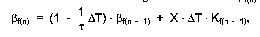
Kf(n-1) als vorangehend berechneter Korrekturkoeffizient,
und
βf(n-1) als vorangehend berechnetes anhaftendes Kraftstoffmengenverhältnis,- die Berechnung des aktuellen Korrekturkoeffizienten Kf(n) gemäß der Gleichung - das Korrigieren der Grund-Kraftstoffeinspritz-Pulsbreite (Tp) mit dem aktuellen Korrekturkoeffizienten Kf(n),- wobei die Berechnung von Kf(n) wiederholt während dem Berechnungszyklus für die Bestimmung der Kraftstoffeinspritz-Pulsbreite (Ti) durchgeführt wird.
 - Verfahren nach Anspruch 1,
dadurch gekennzeichnet, daß
das Kraftstoffhaftverhältnis (X) und/oder die Verdampfungszeitkonstante (τ) entsprechend dem Drosselklappen-Öffnungswinkel (ϑth) und der Drehzahl (N) des Motors bestimmt wird. - Verfahren nach Anspruch 1 und 2,
dadurch gekennzeichnet, daß
das Kraftstoffhaftverhältnis (X) und/oder die Verdampfungszeitkonstante (τ) aus in einer Speichereinheit gespeicherten Kennfeldwerten erhalten werden, die ein Verhältnis zwischen dem Drosselklappen-Öffnungswinkel (ϑth), der Drehzahl (N) des Motors und dem Kraftstoffhaftverhältnis (X) darstellen. - Verfahren nach Anspruch 1-3,
dadurch gekennzeichnet, daß
das Kraftstoffhaftverhältnis (X) und die Verdampfungszeitkonstante (τ) mit dem Einlaßluftstrom (Qa), dem Einlaßkanaldruck, der Grund-Kraftstoffeinspritz-Pulsbreite (Tp) oder einem der Last des Motors entsprechenden Wert bestimmt werden. - Verfahren nach Anspruch 2-4,
dadurch gekennzeichnet, daß
das Kraftstoffhaftverhältnis (X) und/oder die Verdampfungszeitkonstante (τ) in Abhängigkeit von der Kühlwassertemperatur (Tw) bestimmt werden. - Vorrichtung zum Steuern des Kraftstoff/Luft-Verhältnisses von Brennkraftmaschinen mit Kraftstoffeinspritzung, mit- Mitteln zum Erfassen von Betriebsgrößen des Motors, enthaltend:- einen Luftmengensensor (3) zum Bestimmen der Einlaßluftmenge (Qa),- einen Motordrehzahlsensor zum Bestimmen der Drehzahl (N) des Motors,- Kraftstoffeinspritzmittel (13),
und- eine Steuereinheit (15) mit einer I/O-Schaltung, einem A/D-Wandler, einem RAM, einem ROM und einem Mikroprozessor (MPU), die die Kraftstoffeinspritzpulsbreite (Ti) aus einer Grund-Einspritzpulsbreite (Tp) unter Verwendung der erfaßten Betriebsgrößen (Qa, N) berechnen, wobei die Grund-Kraftstoffeinspritzpulsbreite (Tp) basierend auf dem Kraftstoffhaftverhältnis X und der Verdampfungszeitkonstante τ des an dem Einlaßkanal (8) haftenden Kraftstoffs korrigiert wird und wobei die Steuereinheit (15) die Kraftstoffeinspritzmittel (13) betätigt,dadurch gekennzeichnet, daß die Steuereinheit (15)- zu Zeitintervallen ΔT ein anhaftendes Kraftstoffmengenverhältnis βf(n) entsprechend der Gleichung
Kf(n-1) als vorangehend berechneter Korrekturkoeffizient
und
βf(n-1) als vorangehend berechnetes anhaftendes Kraftstoffmengenverhältnis,- den aktuellen Korrekturkoeffizienten Kf(n) gemäß der Gleichung - die Grund-Kraftstoffeinspritz-Pulsbreite (Tp) mit dem aktuellen Korrekturkoeffizienten Kf(n) korrigiert,- wobei die Berechnung von Kf(n) wiederholt innerhalb des Berechnungszyklus der Bestimmung der Kraftstoffeinspritz-Pulsbreite (Ti) durchgeführt wird.
 - Vorrichtung nach Anspruch 6,
dadurch gekennzeichnet, daß
die Steuereinheit (15) das Kraftstoffhaftverhältnis (X) und/oder die Verdampfungszeitkonstante (τ) entsprechend dem erfaßten Drosselklappen-Öffnungswinkel (ϑth) und der Drehzahl (N) des Motors bestimmt. - Vorrichtung nach Anspruch 6 und 7,
dadurch gekennzeichnet, daß
die Steuereinheit (15) das Kraftstoffverhältnis (X) und/oder die Verdampfungszeitkonstante (τ) aus in einer Speichereinheit gespeicherten Werten bestimmt, die das Verhältnis zwischen dem erfaßten Drosselklappen-Öffnungswinkel (ϑth), der Drehzahl (N) des Motors und dem Kraftstoffhaftverhältnis (X) darstellen. - Vorrichtung nach Anspruch 6-8,
dadurch gekennzeichnet, daß
die Steuereinheit (15) das Kraftstoffhaftverhältnis (X) und die Verdampfungszeitkonstante (τ) unter Verwendung der Einlaßluftströmung (Qa), des Einlaßkanaldrucks, der Grund-Kraftstoffeinspritz-Pulsbreite (Tp) oder eines der Last des Motors entsprechenden Werts bestimmt. - Vorrichtung nach Anspruch 6-9,
dadurch gekennzeichnet, daß
die Steuereinheit (15) das Kraftstoffhafverhältnis (X) und/oder die Verdampfungszeitkonstante (τ) in Abhängigkeit von der Kühlwassertemperatur (Tw) bestimmt.
Applications Claiming Priority (2)
| Application Number | Priority Date | Filing Date | Title |
|---|---|---|---|
| JP63232507A JPH07116963B2 (ja) | 1988-09-19 | 1988-09-19 | 空燃比の補正方法、及び、同補正装置 |
| JP232507/88 | 1988-09-19 |
Publications (3)
| Publication Number | Publication Date |
|---|---|
| EP0360193A2 EP0360193A2 (de) | 1990-03-28 |
| EP0360193A3 EP0360193A3 (en) | 1990-06-27 |
| EP0360193B1 true EP0360193B1 (de) | 1992-12-02 |
Family
ID=16940413
Family Applications (1)
| Application Number | Title | Priority Date | Filing Date |
|---|---|---|---|
| EP89117223A Expired - Lifetime EP0360193B1 (de) | 1988-09-19 | 1989-09-18 | Verfahren, um ein Luft/Kraftstoffverhältnis in einer Innenbrennkraftmaschine zu steuern und Einrichtung, um dasselbe zu steuern |
Country Status (5)
| Country | Link |
|---|---|
| US (1) | US4995366A (de) |
| EP (1) | EP0360193B1 (de) |
| JP (1) | JPH07116963B2 (de) |
| KR (1) | KR900005046A (de) |
| DE (1) | DE68903715T2 (de) |
Families Citing this family (13)
| Publication number | Priority date | Publication date | Assignee | Title |
|---|---|---|---|---|
| JPH0460132A (ja) * | 1990-06-29 | 1992-02-26 | Mazda Motor Corp | エンジンの燃料制御装置 |
| JPH04311643A (ja) * | 1991-04-10 | 1992-11-04 | Hitachi Ltd | エンジンの気筒流入空気量算出方法 |
| US5307276A (en) * | 1991-04-25 | 1994-04-26 | Hitachi, Ltd. | Learning control method for fuel injection control system of engine |
| US5261370A (en) * | 1992-01-09 | 1993-11-16 | Honda Giken Kogyo Kabushiki Kaisha | Control system for internal combustion engines |
| JPH06264793A (ja) * | 1993-03-12 | 1994-09-20 | Mazda Motor Corp | エンジンの燃料制御装置 |
| JPH07145771A (ja) * | 1993-11-24 | 1995-06-06 | Honda Motor Co Ltd | 内燃機関の点火時期制御装置 |
| DE4420946B4 (de) * | 1994-06-16 | 2007-09-20 | Robert Bosch Gmbh | Steuersystem für die Kraftstoffzumessung bei einer Brennkraftmaschine |
| JPH0893529A (ja) * | 1994-09-21 | 1996-04-09 | Honda Motor Co Ltd | 内燃機関の燃料噴射制御装置 |
| JPH08177556A (ja) * | 1994-10-24 | 1996-07-09 | Nippondenso Co Ltd | 内燃機関の燃料供給量制御装置 |
| US5546910A (en) * | 1995-07-06 | 1996-08-20 | Ford Motor Company | Air/fuel controller with compensation for secondary intake throttle transients |
| JP3791032B2 (ja) * | 1996-01-09 | 2006-06-28 | 日産自動車株式会社 | 内燃機関の燃料噴射制御装置 |
| KR100231278B1 (ko) * | 1997-04-29 | 1999-12-01 | 류정열 | 자동차 엔진의 공연비제어방법 |
| JP2001329888A (ja) * | 2000-05-18 | 2001-11-30 | Mitsubishi Electric Corp | 内燃機関の燃料噴射制御装置 |
Family Cites Families (9)
| Publication number | Priority date | Publication date | Assignee | Title |
|---|---|---|---|---|
| CA1154121A (en) * | 1979-09-27 | 1983-09-20 | Laszlo Hideg | Fuel metering system for an internal combustion engine |
| US4357923A (en) * | 1979-09-27 | 1982-11-09 | Ford Motor Company | Fuel metering system for an internal combustion engine |
| JPS588238A (ja) * | 1981-07-06 | 1983-01-18 | Toyota Motor Corp | 燃料噴射式エンジンの燃料噴射量制御方法 |
| US4667640A (en) * | 1984-02-01 | 1987-05-26 | Hitachi, Ltd. | Method for controlling fuel injection for engine |
| JP2550014B2 (ja) * | 1984-11-26 | 1996-10-30 | 株式会社日立製作所 | エンジンの燃料噴射制御方法 |
| DE3636810A1 (de) * | 1985-10-29 | 1987-04-30 | Nissan Motor | Kraftstoffeinspritzregelsystem fuer eine brennkraftmaschine |
| JPS6361739A (ja) * | 1986-09-01 | 1988-03-17 | Hitachi Ltd | 燃料制御装置 |
| US4903668A (en) * | 1987-07-29 | 1990-02-27 | Toyota Jidosha Kabushiki Kaisha | Fuel injection system of an internal combustion engine |
| JPH01182552A (ja) * | 1988-01-18 | 1989-07-20 | Hitachi Ltd | 空燃比適応制御装置 |
-
1988
- 1988-09-19 JP JP63232507A patent/JPH07116963B2/ja not_active Expired - Fee Related
-
1989
- 1989-09-08 US US07/404,649 patent/US4995366A/en not_active Expired - Lifetime
- 1989-09-18 EP EP89117223A patent/EP0360193B1/de not_active Expired - Lifetime
- 1989-09-18 DE DE8989117223T patent/DE68903715T2/de not_active Expired - Fee Related
- 1989-09-19 KR KR1019890013439A patent/KR900005046A/ko not_active Withdrawn
Non-Patent Citations (1)
| Title |
|---|
| SAE-PAPER 81 04 94 * |
Also Published As
| Publication number | Publication date |
|---|---|
| DE68903715T2 (de) | 1993-05-13 |
| EP0360193A3 (en) | 1990-06-27 |
| JPH07116963B2 (ja) | 1995-12-18 |
| DE68903715D1 (de) | 1993-01-14 |
| EP0360193A2 (de) | 1990-03-28 |
| KR900005046A (ko) | 1990-04-13 |
| JPH0281935A (ja) | 1990-03-22 |
| US4995366A (en) | 1991-02-26 |
Similar Documents
| Publication | Publication Date | Title |
|---|---|---|
| CA1193341A (en) | Electronic engine control system | |
| EP0326065B1 (de) | Steuerung für Motor-Kraftstoffeinspritzung | |
| US4436073A (en) | Method of and apparatus for controlling the fuel feeding rate of an internal combustion engine | |
| US4964051A (en) | System and method for electronic control of internal combustion engine | |
| EP0360193B1 (de) | Verfahren, um ein Luft/Kraftstoffverhältnis in einer Innenbrennkraftmaschine zu steuern und Einrichtung, um dasselbe zu steuern | |
| US4884540A (en) | Engine speed control method | |
| US5215062A (en) | Fuel control device and method for internal combustion engine | |
| US4938195A (en) | Atmospheric pressure detecting device for engine control | |
| US4440119A (en) | Electronic fuel injecting method and device for internal combustion engine | |
| US4911133A (en) | Fuel injection control system of automotive engine | |
| US4469072A (en) | Method and apparatus for controlling the fuel-feeding rate of an internal combustion engine | |
| US4437445A (en) | Method and apparatus for controlling the fuel feeding rate of an internal combustion engine | |
| US4864997A (en) | Air-fuel ratio control system for an automotive engine | |
| EP0378814B1 (de) | Methode zur Steuerung des Luft-Kraftstoff-Verhältnisses | |
| US6368248B1 (en) | Method and device for controlling a drive unit of a vehicle | |
| US4844042A (en) | Control system for an actuator of an automotive engine | |
| US5031597A (en) | Fuel injection control system for an automotive engine | |
| JPH0251058B2 (de) | ||
| US4508084A (en) | Method for controlling a fuel metering system of an internal combustion engine | |
| JPS6088831A (ja) | 内燃エンジンの作動制御手段の動作特性量制御方法 | |
| US5490417A (en) | Method of determining air density for intake air of automobile engine | |
| EP0535671A2 (de) | Kraftstoffeinspritzsteuerungsvorrichtung für Brennkraftmaschinen | |
| EP0295651B1 (de) | Verfahren und Vorrichtung zum Steuern des Zündzeitpunktes für eine Brennkraftmaschine | |
| US4562819A (en) | Method and apparatus for controlling fuel supply of an internal combustion engine | |
| JPS60249651A (ja) | 電子制御式燃料噴射装置 |
Legal Events
| Date | Code | Title | Description |
|---|---|---|---|
| PUAI | Public reference made under article 153(3) epc to a published international application that has entered the european phase |
Free format text: ORIGINAL CODE: 0009012 |
|
| AK | Designated contracting states |
Kind code of ref document: A2 Designated state(s): DE FR GB |
|
| PUAL | Search report despatched |
Free format text: ORIGINAL CODE: 0009013 |
|
| AK | Designated contracting states |
Kind code of ref document: A3 Designated state(s): DE FR GB |
|
| 17P | Request for examination filed |
Effective date: 19900629 |
|
| 17Q | First examination report despatched |
Effective date: 19910212 |
|
| GRAA | (expected) grant |
Free format text: ORIGINAL CODE: 0009210 |
|
| AK | Designated contracting states |
Kind code of ref document: B1 Designated state(s): DE |
|
| REF | Corresponds to: |
Ref document number: 68903715 Country of ref document: DE Date of ref document: 19930114 |
|
| EN | Fr: translation not filed | ||
| PLBE | No opposition filed within time limit |
Free format text: ORIGINAL CODE: 0009261 |
|
| STAA | Information on the status of an ep patent application or granted ep patent |
Free format text: STATUS: NO OPPOSITION FILED WITHIN TIME LIMIT |
|
| 26N | No opposition filed | ||
| PGFP | Annual fee paid to national office [announced via postgrant information from national office to epo] |
Ref country code: DE Payment date: 20030908 Year of fee payment: 15 |
|
| PG25 | Lapsed in a contracting state [announced via postgrant information from national office to epo] |
Ref country code: DE Free format text: LAPSE BECAUSE OF NON-PAYMENT OF DUE FEES Effective date: 20050401 |