EP0360249A2 - Vorrichtung zum Abtasten von Warendaten - Google Patents
Vorrichtung zum Abtasten von Warendaten Download PDFInfo
- Publication number
- EP0360249A2 EP0360249A2 EP89117402A EP89117402A EP0360249A2 EP 0360249 A2 EP0360249 A2 EP 0360249A2 EP 89117402 A EP89117402 A EP 89117402A EP 89117402 A EP89117402 A EP 89117402A EP 0360249 A2 EP0360249 A2 EP 0360249A2
- Authority
- EP
- European Patent Office
- Prior art keywords
- bar code
- reading apparatus
- support post
- data reading
- commodity
- Prior art date
- Legal status (The legal status is an assumption and is not a legal conclusion. Google has not performed a legal analysis and makes no representation as to the accuracy of the status listed.)
- Withdrawn
Links
Images


Classifications
-
- G—PHYSICS
- G06—COMPUTING OR CALCULATING; COUNTING
- G06K—GRAPHICAL DATA READING; PRESENTATION OF DATA; RECORD CARRIERS; HANDLING RECORD CARRIERS
- G06K7/00—Methods or arrangements for sensing record carriers, e.g. for reading patterns
- G06K7/10—Methods or arrangements for sensing record carriers, e.g. for reading patterns by electromagnetic radiation, e.g. optical sensing; by corpuscular radiation
- G06K7/10544—Methods or arrangements for sensing record carriers, e.g. for reading patterns by electromagnetic radiation, e.g. optical sensing; by corpuscular radiation by scanning of the records by radiation in the optical part of the electromagnetic spectrum
- G06K7/10821—Methods or arrangements for sensing record carriers, e.g. for reading patterns by electromagnetic radiation, e.g. optical sensing; by corpuscular radiation by scanning of the records by radiation in the optical part of the electromagnetic spectrum further details of bar or optical code scanning devices
- G06K7/1096—Methods or arrangements for sensing record carriers, e.g. for reading patterns by electromagnetic radiation, e.g. optical sensing; by corpuscular radiation by scanning of the records by radiation in the optical part of the electromagnetic spectrum further details of bar or optical code scanning devices the scanner having more than one scanning window, e.g. two substantially orthogonally placed scanning windows for integration into a check-out counter of a super-market
-
- A—HUMAN NECESSITIES
- A47—FURNITURE; DOMESTIC ARTICLES OR APPLIANCES; COFFEE MILLS; SPICE MILLS; SUCTION CLEANERS IN GENERAL
- A47F—SPECIAL FURNITURE, FITTINGS, OR ACCESSORIES FOR SHOPS, STOREHOUSES, BARS, RESTAURANTS OR THE LIKE; PAYING COUNTERS
- A47F9/00—Shop, bar, bank or like counters
- A47F9/02—Paying counters
- A47F9/04—Check-out counters, e.g. for self-service stores
- A47F9/046—Arrangement of recording means in or on check-out counters
-
- G—PHYSICS
- G06—COMPUTING OR CALCULATING; COUNTING
- G06K—GRAPHICAL DATA READING; PRESENTATION OF DATA; RECORD CARRIERS; HANDLING RECORD CARRIERS
- G06K7/00—Methods or arrangements for sensing record carriers, e.g. for reading patterns
- G06K7/10—Methods or arrangements for sensing record carriers, e.g. for reading patterns by electromagnetic radiation, e.g. optical sensing; by corpuscular radiation
- G06K7/10544—Methods or arrangements for sensing record carriers, e.g. for reading patterns by electromagnetic radiation, e.g. optical sensing; by corpuscular radiation by scanning of the records by radiation in the optical part of the electromagnetic spectrum
- G06K7/10821—Methods or arrangements for sensing record carriers, e.g. for reading patterns by electromagnetic radiation, e.g. optical sensing; by corpuscular radiation by scanning of the records by radiation in the optical part of the electromagnetic spectrum further details of bar or optical code scanning devices
- G06K7/10861—Methods or arrangements for sensing record carriers, e.g. for reading patterns by electromagnetic radiation, e.g. optical sensing; by corpuscular radiation by scanning of the records by radiation in the optical part of the electromagnetic spectrum further details of bar or optical code scanning devices sensing of data fields affixed to objects or articles, e.g. coded labels
- G06K7/10871—Methods or arrangements for sensing record carriers, e.g. for reading patterns by electromagnetic radiation, e.g. optical sensing; by corpuscular radiation by scanning of the records by radiation in the optical part of the electromagnetic spectrum further details of bar or optical code scanning devices sensing of data fields affixed to objects or articles, e.g. coded labels randomly oriented data-fields, code-marks therefore, e.g. concentric circles-code
Definitions
- the present invention relates to a commodity data reading apparatus with a bar code reader which has scanning means supported on a support post fixed to a commodity receiving base to project in a direction crossing a commodity placing surface of the receiving base, the scanning means scanning a bar code mounted on a commodity when the commodity passes over the placing surface.
- the above described type of the commodity data reading apparatus has been used in a check out system installed in a super market, for example.
- Figs. 1 through 3 show a conventional commodity data reading apparatus of the above type, which is used in a supermarket.
- a support post 14 projecting vertically upward is mounted at the center of one side edge of the rectangular and horizontal commodity placing surface 12 of a check table 10, and the placing surface 12 is mounted on the top surface of the table 10.
- a bar code read window 16 is formed in the center portion of one side surface of the post 14, one side surface being located at the placing surface side.
- a scanner of the bar code reader (not shown) is disposed inside the post 14 to face the window 16.
- a stopper 18 as a rubber stripe lies in the right part (as viewed in the drawings of Figs. 1 and 2) of the placing surface 12 so as to be located at a position near the support post 14 and to extend in a width direction of the placing surface 12.
- the right part of the placing surface 12 with respect to the stopper 18 in Figs. 1 and 2 is used as a basket receiving area 12a on which a basket 26a containing commodities that have not been inputted their commodity data.
- the left part of the placing surface 12 of the stand 10 is used as a basket sending-out area 12b on which an empty basket 26b to be received data-inputted commodities.
- An empty basket 26b can be placed at a narrow portion 12c in front of the post 14 on the sending-out area 12b of the placing surface 12 in such a way that its longitudinal edges extend parallel to the longitudinal edges of the surface 12, as is shown in Fig. 2.
- an operator or cashier 25 stands on one side of the check stand 10, which is remote from the support post 14, while a purchaser stands on the other side of the stand 10.
- the purchaser places a basket 26a, in which commodities that he or she wants to purchase, on the basket receiving area 12a of the placing surface 12 of the check stand 10.
- the scanner which is located within the support post 14 to face the window 16, is scanning a predetermined range in a space indicated by a one-dot chain line in Fig. 3, with a laser beam, the operator 25 holding the commodity must pass the bar code on the commodity within the predetermined range. Further, the bar code displaying area on the outer surface of the commodity must be crossed the laser beam applied in the predetermined range at an angle within a predetermined range.
- the operator 25 must finally use the keyboard 20 on the support post 14 to enter the predetermined commodity data about the commodity to a cash register as a Point Of Sales terminal with which the bar code reader is connected.
- an object of the present invention is to provide a commodity data reading apparatus of the above described kind, which can surely increase the possibility of that the scanner can exactly read the bar code on the commodity by only one time passing of the commodity in front of the support post in which the scanner of the bar code reader is housed, and can reduce the attentiveness required while the operator holds the commodity and passes it in front of the support post, therefore can reduce the operator's physical and mental fatigue and can reduce a wait by the purchaser.
- a commodity data reading apparatus comprises: a commodity receiving base having a commodity placing surface; a support post projecting in a direction to cross a commodity placing surface of the receiving base; and a bar code reader having a plurality of scanners arranged at different positions on the support post.
- the scanners of the bar code reader arranged at different positions on the support post enlarge a scanning area of the bar code reader, and broadens a tolerable angle range of the inclination of the bar code displaying area on the outer surface of the commodity with respect to the laser beam direction within the scanning area.
- FIGs. 4 and 5 schematically show an appearance of a commodity data reading apparatus according to an embodiment of the present invention.
- like reference numerals are used for designating like or equivalent portions in Figs. 1 through 3 illustrating the conventional commodity data reading apparatus already mentioned.
- the structure of a check table 10 as a commodity receiving base of this embodiment is substantially the same as that of the above described conventional apparatus.
- This embodiment is, however, different from the above described conventional apparatus in the structure of the support post 14 and the construction of the bar code reader.
- a first bar code read window 30 is formed in the upper end portion of the front surface 28a (a portion of the circumferential surface located near the placing surface 12) of the vertically extending portion 28 of the support 14.
- a second bar code read window 34 is formed in the central portion of the front surface 32a of the upper-side bend portion 32.
- a scanner 35a is disposed in the vertical extending portion 28 to face the first window 30.
- Another scanner 35b is disposed in the bend portion 32 to face the second window 34.
- These scanners 35a and 35b respectively emit laser beams for reading a bar code on a commodity, through the first and second windows 30 and 34 to the space outside the support post 14. Scanning ranges by the laser beams emitted from the scanners 35a and 35b are indicated by reference marks A and B.
- these scanning ranges A, B partially overlap with each other. More exactly, the lower part of the scanning range B overlaps with the upper part of the scanning range A, so that a scanning range C by the bar code reader is substantially equal to the sum of the scanning ranges A and B by the scanners 35a and 35b.
- the scanners 35a and 35b emit the laser beams to cross each other in the outside of the support post 14.
- a keyboard 20 and a card insertion slit 36 are provided on the projected end surface 32b of the support post 14.
- a card reader (not shown) is provided inside the slit 36. When a recording card such as magnetic card that is owned by an operator is inserted into the slit 36, the card reader reads a predetermined data from the card and enter the data into a Point Of Sales (POS) terminal such as a cash register connected with the bar code reader.
- POS Point Of Sales
- a display panel 24a for an operator is arranged on the projected end surface 32b to extend along the upper edge thereof.
- Another display panel 24b for a customer is arranged on the rear surface 32c (a portion of the circumferential surface located far away from the placing surface 12) of the bend portion 32 of the post 14 to extend along the upper edge thereof.
- Fig. 6 schematically shows the construction of the bar code reader with the two scanners 35a and 35b.
- Each of the scanners 35a and 35b has CPU 40. Since the two scanners 35a, 35b have the same constructions, only the construction of one scanner 35a is shown in Fig. 1.
- a CPU 40 is connected through a communication interface 42 with a Point Of Sales terminal 44 such as a cash register.
- the keyboard 20 and the card reader mounted in the card insertion slit 36 are also connected with the POS terminal 44, such as a cash register.
- Commodity data read from a bar code on the commodity by the scanners 35a and 35b, and the data inputted by the keyboard 20 or the card reader are sent to the POS terminal 44.
- the POS terminal processes the inputted data in a predetermined manner, and a signal from the POS terminal 44 is transferred to the CPU 40.
- a priority decision circuit 46 is connected with the CPU 40.
- the circuit 46 is used to decide which one of the same two commodity data, read from one bar code on one commodity by the two scanners 35a and 35b in the overlapping region of the two scanning ranges A and B, must be processed prior to another commodity data.
- a motor controller 48 applies a laser beam to the scanning/collecting means 52.
- the means 52 scans a bar code 56 on a commodity with the laser beam.
- a laser beam reflected from the bar code is received by the means 52, and is detected by a reflected light detector 58.
- the detector 58 converts the reflected light signal corresponding to the scanned bar code into a corresponding electric signal, and transmits its electric signal through an analog amplifier 60 and an analog-digital (A/D) converter 62 to the CPU 40.
- A/D analog-digital
- the priority decision circuit 46 is connected at its two request signal terminals REQT1 and REQT2, and at its time acknowledge signal terminals ACKT1 and ACKT2 with the CPU 40 of each of the two scanners 35a and 35b.
- the two request signal terminals REQT1 and REQT2 are further connected through an OR gate 64 to a timer 66.
- the timer 66 is connected with the circuit 46 to supplies an enable signal EN to the circuit 46.
- the operation of the priority decision circuit 46 is based on the fact that when the two scanners 35a and 35b read one bar code on one commodity within the overlapping region of the two scanning areas A and B, the timings of the data readings by the two scanners 35a and 35b will never be coincident with each other. Supposing that the upper scanner 35b which is connected to one request signal terminal REQT2 reads one bar code on one commodity earlier than the lower scanner 35a which is connected to the other request signal terminal REQT1, one request signal REQ2 earlier reaches the priority decision circuit 46 and the OR gate 64 than the other request signal REQ1, as shown in Fig. 8.
- the acknowledge signal ACK1 or ACK2 corresponding to the later applied request signal REQ1 or REQ2 is not send out from the circuit 46. Therefore, the signal corresponding to one bar code will never be inputted two times to the POS terminal 44. Consequently, the commodity data relating to one commodity will never be inputted two times to the POS terminal 44.
- Fig. 9 schematically shows another circuit used, instead of the priority decision circuit 46, in the commodity data reading apparatus of Fig. 4.
- the circuit of Fig. 9 is mounted in the POS terminal 44 to process two commodity data read from one bar code on one commodity by the two scanners 35a and 35b.
- the scanners 35a and 35b are connected with a CPU 71 of the POS terminal 44, through a communication interface 68 and a data select controller 70.
- the output of the communication interface 68 is connected to an OR gate 72 whose output is connected to two timers 74 and 76 that are connected in series. These timers 74 and 76 are connected to the enable terminals ENT1 and ENT2 of the data select controller 70.
- the second timer 76 starts to operate. Neither of the bar code corresponding signals, inputted to the data select controller 70 during the period of time T2 that the second timer 76 operates, will be sent out to the CPU 71. In this way, a signal corresponding to one bar code will never be transmitted two times to the POS terminal 44.
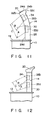
- the support post 14 may be a vertically straight shape, as is shown in Fig. 12.
- two scanners 35a and 35b must be arranged at two vertically separated positions on the straight support post 14 so that two laser beam emitted directions from the two scanners 35a, 35b cross each other and two scanning regions A and B are partially overlapped with each other, as shown.
Landscapes
- Physics & Mathematics (AREA)
- Engineering & Computer Science (AREA)
- Electromagnetism (AREA)
- Health & Medical Sciences (AREA)
- General Health & Medical Sciences (AREA)
- Toxicology (AREA)
- Artificial Intelligence (AREA)
- Computer Vision & Pattern Recognition (AREA)
- General Physics & Mathematics (AREA)
- Theoretical Computer Science (AREA)
- Cash Registers Or Receiving Machines (AREA)
- Mechanical Optical Scanning Systems (AREA)
Applications Claiming Priority (2)
| Application Number | Priority Date | Filing Date | Title |
|---|---|---|---|
| JP63237364A JP2732497B2 (ja) | 1988-09-21 | 1988-09-21 | 商品データ読取装置 |
| JP237364/88 | 1988-09-21 |
Publications (2)
| Publication Number | Publication Date |
|---|---|
| EP0360249A2 true EP0360249A2 (de) | 1990-03-28 |
| EP0360249A3 EP0360249A3 (de) | 1991-10-16 |
Family
ID=17014295
Family Applications (1)
| Application Number | Title | Priority Date | Filing Date |
|---|---|---|---|
| EP19890117402 Withdrawn EP0360249A3 (de) | 1988-09-21 | 1989-09-20 | Vorrichtung zum Abtasten von Warendaten |
Country Status (4)
| Country | Link |
|---|---|
| US (1) | US5042619A (de) |
| EP (1) | EP0360249A3 (de) |
| JP (1) | JP2732497B2 (de) |
| KR (1) | KR930000678B1 (de) |
Cited By (7)
| Publication number | Priority date | Publication date | Assignee | Title |
|---|---|---|---|---|
| EP0420643A1 (de) * | 1989-09-29 | 1991-04-03 | NCR International, Inc. | Verkaufsstellendatenterminal |
| EP0360250A3 (de) * | 1988-09-20 | 1991-10-16 | Kabushiki Kaisha TEC | Optische Abtastvorrichtung |
| EP0480348A1 (de) * | 1990-10-09 | 1992-04-15 | Datalogic S.P.A. | Laserstrahlstreifencodeleser |
| EP0490603A1 (de) * | 1990-12-10 | 1992-06-17 | Ncr International Inc. | Optischer Abtastapparat zum Lesen von verschlüsselten Symbolen |
| US5293033A (en) * | 1988-09-20 | 1994-03-08 | Tokyo Electric Co., Ltd. | Optical reading apparatus |
| US5459308A (en) * | 1991-09-30 | 1995-10-17 | Ncr Corporation | Dual aperature optical scanner |
| NL1011635C2 (nl) * | 1999-03-22 | 2000-09-27 | Beheermij Van Der Loo B V | Inrichting voor het herkennen van voorwerpen. |
Families Citing this family (31)
| Publication number | Priority date | Publication date | Assignee | Title |
|---|---|---|---|---|
| US5448046A (en) * | 1987-12-28 | 1995-09-05 | Symbol Technologies, Inc. | Arrangement for and method of expediting commercial product transactions at a point-of-sale site |
| US5128520A (en) | 1989-08-11 | 1992-07-07 | Spectra-Physics, Inc. | Scanner with coupon validation |
| US5206491A (en) * | 1990-03-02 | 1993-04-27 | Fujitsu Limited | Plural beam, plural window multi-direction bar code reading device |
| US5178234A (en) * | 1990-03-15 | 1993-01-12 | Tokyo Electric Co., Ltd. | Checkout apparatus |
| USRE35455E (en) * | 1990-03-15 | 1997-02-18 | Kabushiki Kaisha Tec | Checkout apparatus |
| JP2823022B2 (ja) * | 1990-04-02 | 1998-11-11 | 富士通株式会社 | Pos用バーコードスキャナ |
| US5491328A (en) | 1991-09-24 | 1996-02-13 | Spectra-Physics Scanning Systems, Inc. | Checkout counter scanner having multiple scanning surfaces |
| JP2727037B2 (ja) * | 1992-04-20 | 1998-03-11 | 富士通株式会社 | バーコード読取り装置 |
| US5475207A (en) * | 1992-07-14 | 1995-12-12 | Spectra-Physics Scanning Systems, Inc. | Multiple plane scanning system for data reading applications |
| JP3441580B2 (ja) | 1995-12-14 | 2003-09-02 | 富士通株式会社 | 読取装置 |
| ES2162744B1 (es) * | 1997-11-03 | 2003-02-16 | Loimil Francisco J Marque | Sistema electronico de control de suministro de agua y electricidad a barcos para puertos deportivos. |
| JP3881792B2 (ja) | 1998-10-21 | 2007-02-14 | 富士通株式会社 | 光走査装置、コード読取装置およびバーコード読取装置 |
| US6381417B1 (en) * | 1998-11-04 | 2002-04-30 | Canon Kabushiki Kaisha | Data reading apparatus |
| US6155489A (en) * | 1998-11-10 | 2000-12-05 | Ncr Corporation | Item checkout device including a bar code data collector and a produce data collector |
| US6164533A (en) * | 1998-11-12 | 2000-12-26 | Barton; Blain | Point of sale automatic savings program contribution system |
| WO2000045391A1 (en) * | 1999-01-29 | 2000-08-03 | Sharper Image Corporation | A rack for compact discs |
| US7100832B2 (en) | 2000-04-18 | 2006-09-05 | Metrologic Instruments, Inc. | Bioptical laser scanning system providing 360° of omnidirectional bar code symbol scanning coverage at point of sale station |
| US20030132291A1 (en) | 2002-01-11 | 2003-07-17 | Metrologic Instruments, Inc. | Point of sale (POS) station having bar code reading system with integrated internet-enabled customer-kiosk terminal |
| US20060038009A1 (en) | 2002-01-11 | 2006-02-23 | Metrologic Instruments, Inc. | Point of sale (POS) based bar code reading and cash register systems with integrated internet-enabled customer-kiosk terminals |
| US7296748B2 (en) | 2002-01-11 | 2007-11-20 | Metrologic Instruments, Inc. | Bioptical laser scanning system providing 360° of omnidirectional bar code symbol scanning coverage at point of sale station |
| US20030149629A1 (en) * | 2002-02-06 | 2003-08-07 | Claridge Bo. T. | Method of point of sale investment |
| US20030226813A1 (en) * | 2002-06-05 | 2003-12-11 | Taylor Charles E. | Storage and display rack for DVDs |
| US6955267B2 (en) * | 2002-06-05 | 2005-10-18 | Sharper Image Corporation | Storage and display rack for DVDs |
| JP2004249499A (ja) * | 2003-02-18 | 2004-09-09 | Canon Inc | 画像形成システム |
| US20060047589A1 (en) * | 2004-08-30 | 2006-03-02 | Mr. Edward Grau | Investment program contribution system |
| DE102005014626B4 (de) * | 2005-03-23 | 2018-06-21 | Bizerba SE & Co. KG | Waage |
| USD668656S1 (en) * | 2011-01-24 | 2012-10-09 | Datalogic ADC, Inc. | Tunnel scanner |
| US8523076B2 (en) | 2012-01-10 | 2013-09-03 | Metrologic Instruments, Inc. | Omnidirectional laser scanning bar code symbol reader generating a laser scanning pattern with a highly non-uniform scan density with respect to line orientation |
| US9004359B2 (en) | 2012-05-16 | 2015-04-14 | Datalogic ADC, Inc. | Optical scanner with top down reader |
| JP2018101365A (ja) * | 2016-12-21 | 2018-06-28 | 東芝テック株式会社 | 読取装置 |
| JP7334717B2 (ja) * | 2020-12-07 | 2023-08-29 | 株式会社ダイフク | 洗車機 |
Family Cites Families (17)
| Publication number | Priority date | Publication date | Assignee | Title |
|---|---|---|---|---|
| US3960420A (en) * | 1974-05-08 | 1976-06-01 | Ncr Corporation | Checkout system |
| JPS522445A (en) * | 1975-06-24 | 1977-01-10 | Ushio Inc | Information recording apparatus |
| JPS5326624A (en) * | 1976-08-25 | 1978-03-11 | Mitsubishi Electric Corp | Bar-code label reading device |
| FR2395080A1 (fr) * | 1977-06-21 | 1979-01-19 | Kronenbourg Brasseries | Installation pour l'identification automatique des futs |
| US4473746A (en) * | 1981-07-30 | 1984-09-25 | Bell & Howell Company | Multiple head optical scanner |
| JPS596260U (ja) * | 1982-06-30 | 1984-01-14 | 富士通株式会社 | バ−コ−ド読取り作業装置 |
| JPS5957366A (ja) * | 1982-09-28 | 1984-04-02 | Fujitsu Ltd | パタ−ン検査方法 |
| JPS59197967A (ja) * | 1983-04-25 | 1984-11-09 | Nec Corp | 固定スキヤナ装置 |
| JPS60205773A (ja) * | 1984-03-30 | 1985-10-17 | Teraoka Seiko Co Ltd | 商品デ−タ入力装置 |
| JPS61163572A (ja) * | 1985-01-11 | 1986-07-24 | Matsushita Electric Ind Co Ltd | ボタン型空気電池の製造法 |
| JPS61228584A (ja) * | 1985-04-01 | 1986-10-11 | Toshiba Corp | バ−コ−ド自動読取装置 |
| US4652732A (en) * | 1985-09-17 | 1987-03-24 | National Semiconductor Corporation | Low-profile bar code scanner |
| US4882476A (en) * | 1986-09-10 | 1989-11-21 | Norand Corporation | Bar code reader with enhanced sensitivity |
| JPH083824B2 (ja) * | 1987-02-04 | 1996-01-17 | 株式会社テック | バ−コ−ドスキヤナ |
| CA1301903C (en) * | 1987-07-28 | 1992-05-26 | Yukuo Kurimoto | Check-out counter table |
| JPS6345666A (ja) * | 1987-08-10 | 1988-02-26 | Hitachi Ltd | デイジタル制御システム |
| CA1325473C (en) * | 1988-09-20 | 1993-12-21 | Yasuhisa Yamashita | Optical reading apparatus |
-
1988
- 1988-09-21 JP JP63237364A patent/JP2732497B2/ja not_active Expired - Lifetime
-
1989
- 1989-09-15 US US07/407,939 patent/US5042619A/en not_active Expired - Lifetime
- 1989-09-19 KR KR1019890013468A patent/KR930000678B1/ko not_active Expired - Lifetime
- 1989-09-20 EP EP19890117402 patent/EP0360249A3/de not_active Withdrawn
Cited By (10)
| Publication number | Priority date | Publication date | Assignee | Title |
|---|---|---|---|---|
| EP0360250A3 (de) * | 1988-09-20 | 1991-10-16 | Kabushiki Kaisha TEC | Optische Abtastvorrichtung |
| US5293033A (en) * | 1988-09-20 | 1994-03-08 | Tokyo Electric Co., Ltd. | Optical reading apparatus |
| EP0420643A1 (de) * | 1989-09-29 | 1991-04-03 | NCR International, Inc. | Verkaufsstellendatenterminal |
| EP0480348A1 (de) * | 1990-10-09 | 1992-04-15 | Datalogic S.P.A. | Laserstrahlstreifencodeleser |
| EP0490603A1 (de) * | 1990-12-10 | 1992-06-17 | Ncr International Inc. | Optischer Abtastapparat zum Lesen von verschlüsselten Symbolen |
| US5459308A (en) * | 1991-09-30 | 1995-10-17 | Ncr Corporation | Dual aperature optical scanner |
| US6059189A (en) * | 1991-09-30 | 2000-05-09 | Ncr Corporation | Dual aperture optical scanner |
| US6536668B1 (en) | 1991-09-30 | 2003-03-25 | Ncr Corporation | Dual aperture optical scanner |
| NL1011635C2 (nl) * | 1999-03-22 | 2000-09-27 | Beheermij Van Der Loo B V | Inrichting voor het herkennen van voorwerpen. |
| WO2000057346A1 (en) * | 1999-03-22 | 2000-09-28 | Beheermaatschappij Van Der Loo B.V. | Device for recognizing objects |
Also Published As
| Publication number | Publication date |
|---|---|
| KR900005332A (ko) | 1990-04-14 |
| JPH0285983A (ja) | 1990-03-27 |
| US5042619A (en) | 1991-08-27 |
| JP2732497B2 (ja) | 1998-03-30 |
| KR930000678B1 (ko) | 1993-01-29 |
| EP0360249A3 (de) | 1991-10-16 |
Similar Documents
| Publication | Publication Date | Title |
|---|---|---|
| EP0360249A2 (de) | Vorrichtung zum Abtasten von Warendaten | |
| US5252814A (en) | Multi-scanner checkout counter using digitizer panel to determine X-Y location of scanned items | |
| EP0421673B1 (de) | Überprüfungssystem | |
| EP2168075B1 (de) | Bildgebungslesegerät mit mehreren festkörperbildgebern zum elektrooptischen lesen von freimachungsvermerken | |
| US6330973B1 (en) | Integrated code reading systems including tunnel scanners | |
| EP0288555B1 (de) | Ausgabestelle mit optischem abtaster | |
| EP0490603A1 (de) | Optischer Abtastapparat zum Lesen von verschlüsselten Symbolen | |
| KR101998525B1 (ko) | 무인 계산대 | |
| EP0390448A1 (de) | Tragbares Abschlussverfahrenssystem | |
| JP5328278B2 (ja) | セルフposシステム | |
| US7717235B2 (en) | Convertible point-of-sale checkout terminal | |
| US20100200656A1 (en) | Full-or self-service, point-of-sale, checkout terminal | |
| JP2009093424A (ja) | データコード読取装置 | |
| JP5663070B2 (ja) | セルフposシステム | |
| US5043563A (en) | Portable overhead bar code scanner | |
| US20080296388A1 (en) | Compact, ergonomic imaging reader and method | |
| US9245425B2 (en) | Produce lift apparatus | |
| JP3669630B2 (ja) | スキャナ装置および商品コードの入力方法 | |
| EP1380983B1 (de) | Kodelesesystem mit Klangregelung für hörbares Signal | |
| EP0490602A1 (de) | Optischer Abtastapparat zum Lesen von verschlüsselten Symbolen | |
| EP0490657A1 (de) | Kompaktes optisches Abtastsystem | |
| US8733651B2 (en) | Low profile tri-aperture optical code scanner | |
| US20070175996A1 (en) | Imaging reader and method with tall field of view | |
| JPH1021323A (ja) | バーコード読取装置 | |
| JP2734727B2 (ja) | バーコード読取装置 |
Legal Events
| Date | Code | Title | Description |
|---|---|---|---|
| PUAI | Public reference made under article 153(3) epc to a published international application that has entered the european phase |
Free format text: ORIGINAL CODE: 0009012 |
|
| 17P | Request for examination filed |
Effective date: 19890922 |
|
| AK | Designated contracting states |
Kind code of ref document: A2 Designated state(s): DE FR GB |
|
| PUAL | Search report despatched |
Free format text: ORIGINAL CODE: 0009013 |
|
| AK | Designated contracting states |
Kind code of ref document: A3 Designated state(s): DE FR GB |
|
| 17Q | First examination report despatched |
Effective date: 19930525 |
|
| STAA | Information on the status of an ep patent application or granted ep patent |
Free format text: STATUS: THE APPLICATION IS DEEMED TO BE WITHDRAWN |
|
| 18D | Application deemed to be withdrawn |
Effective date: 19931005 |