EP0360585A2 - Schienenwagen und dessen Konstruktionsverfahren - Google Patents
Schienenwagen und dessen Konstruktionsverfahren Download PDFInfo
- Publication number
- EP0360585A2 EP0360585A2 EP89309563A EP89309563A EP0360585A2 EP 0360585 A2 EP0360585 A2 EP 0360585A2 EP 89309563 A EP89309563 A EP 89309563A EP 89309563 A EP89309563 A EP 89309563A EP 0360585 A2 EP0360585 A2 EP 0360585A2
- Authority
- EP
- European Patent Office
- Prior art keywords
- units
- shell
- compartment units
- compartment
- railway carriage
- Prior art date
- Legal status (The legal status is an assumption and is not a legal conclusion. Google has not performed a legal analysis and makes no representation as to the accuracy of the status listed.)
- Granted
Links
Images




Classifications
-
- B—PERFORMING OPERATIONS; TRANSPORTING
- B61—RAILWAYS
- B61D—BODY DETAILS OR KINDS OF RAILWAY VEHICLES
- B61D35/00—Sanitation
- B61D35/005—Toilet facilities
-
- B—PERFORMING OPERATIONS; TRANSPORTING
- B61—RAILWAYS
- B61D—BODY DETAILS OR KINDS OF RAILWAY VEHICLES
- B61D1/00—Carriages for ordinary railway passenger traffic
- B61D1/02—General arrangements in sleeping or couchette carriages
-
- B—PERFORMING OPERATIONS; TRANSPORTING
- B61—RAILWAYS
- B61D—BODY DETAILS OR KINDS OF RAILWAY VEHICLES
- B61D1/00—Carriages for ordinary railway passenger traffic
- B61D1/04—General arrangements of seats
-
- B—PERFORMING OPERATIONS; TRANSPORTING
- B61—RAILWAYS
- B61D—BODY DETAILS OR KINDS OF RAILWAY VEHICLES
- B61D17/00—Construction details of vehicle bodies
- B61D17/04—Construction details of vehicle bodies with bodies of metal; with composite, e.g. metal and wood body structures
- B61D17/043—Construction details of vehicle bodies with bodies of metal; with composite, e.g. metal and wood body structures connections between superstructure sub-units
- B61D17/045—The sub-units being construction modules
Definitions
- This invention relates to a method for assembling railway carriages or similar constructions, as referred to in the preamble of claim 1.
- the invention also relates to railway carriages or the like assembled by using the method.
- the assembly of railway carriages or similar constructions normally includes building a framework onto which are attached elements to form an outer shell and, when this is completed, the carriage is provided with its interior fittings including the building of sitting or sleeping cabins, toilets, recreation rooms, catering facilities, etc. inside the shell.
- the major disadvantage of such a system is that the assembly phase for the interior fittings is slow and difficult in the restricted space available within the shell and requires a high degree of manual work.
- One aim of this invention is to provide a method of producing railway carriages or other similar constructions which allows production of the frame, shell, undercarriage and other heavy metal parts of the carriage to a high state of completion and, on the other hand, allows prefabrication of the individual units or compartments, which are required within the shell, independently of the first mentioned production.
- These units or compartments can be fully fitted out to serve a variety of purposes e.g. sitting compartments, sleeping cabins, toilet and/or shower compartments, video or children's compartments, or catering facilities.
- the invention in its method aspect is defined in the following claim 1 and in terms of a railway carriage or the like in the following claim 6.
- Necessary services such as electric wiring, plumbing and air conditioning piping can be fitted in the shell before the prefabricated units are introduced, although care must be taken not to obstruct the movement path of the units.
- these wires and pipes will be enclosed in intermediate spaces between the shell and the units and can then be connected, for instance in connecting boxes provided for this purpose, to the corresponding service equipment already installed in the units. Thereby the installation of wiring and piping is greatly simplified.
- a so-called technical module may be used for interconnecting two railway carriages and their technical functions. This is positioned at the end of one carriage and includes the necessary terminals for attachment to the corresponding services in the adjacent carriage. Such a technical module, together with the corridor connecting the carriages and other equipment, can form a separate unit which may conveniently act as the closing element for the opening into the shell, when said opening is at the end of the carriage.
- the bottom structure of the carriage is desirably flat and unobstructed in order that the individual units or compartments may be moved freely and rapidly from the opening in the shell to their correct location in the carriage and secured in their correct location.
- the bottom structure of the carriage is fitted with a floor surface of a type which will serve the needs of the different compartment units. This means that the individual compartment units need no floor of their own, which facilitates bringing each compartment unit into its correct location, because moving a compartment unit can be achieved by pushing from inside the compartment unit. This can be a considerable advantage when positioning compartment units close together in the confined space available within the shell.
- Figure 1 shows the shell of a railway carriage, made up of side wall elements 1, end walls 2, a base element 3 and a roof element 4. At least one of the end walls 2, which can also be a self-supporting element, acts as the closing element for the opening 5 leading to the interior of the shell, and includes the corridor K. Alternatively one side wall element 1 may act as the closing element for a side opening 6, in which case compartment units can be moved into the shell over the entire length of the side wall. Each side wall element 1 is prefabricated with windows 7 and outer doors 8.
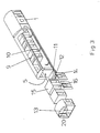
- FIG 2 shows an embodiment of the invention in which compartment units are being moved into the shell via the end opening 5.
- Air conditioning piping 9 and electrical cables 10 are shown - and a low pressure tank 11 and a water tank 12 are connected with the carriage's water/drainage system.
- These technical services for the carriage are connected to the corresponding systems in the rest of the train by means of a technical unit 13.
- the service items 9-12 are built in as part of the prefabrication of the elements 1, 3 and 4, being attached to or fabricated in the appropriate elements.
- Integer 14 in Figure 2 shows an internal wall for attachment to the inside of one of the side wall elements 1.
- a prefabricated self-supporting unit 15 shown in Figure 2 comprises a WC-module 16, the electrical, air conditioning and plumbing systems of which are all in-built and are designed to be connected to the corresponding services in the shell after the unit 15 is moved into place and attached to the shell. Also in Figure 2 water pipe connections 17 and low pressure drain connections 18 are shown, which are so arranged that an unimpeded path remains for moving the units inside the shell.
- the floor of the carriage is marked 19 in Figure 2 and the unit 15 can be attached to the floor 19 which is fixed on the base element 3.
- FIG 3 shows an alternative embodiment wherein instead of an end wall 2 serving to close the shell, a separate self-supporting end element or technical module 20 is used as the closing means.
- the module 20 is made up from an interior wall construction comprising the technical unit 13 and corridor opening K. This alternative has the advantage over the embodiment shown in Figure 1 that the positioning of the technical unit 13 is independent of the moving of the units 15.
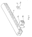
- Figure 4 shows an arrangement whereby a unit 15 is being moved into the shell via an opening 6 in one side wall element 1.
- a closing member 1a is used which completes the side wall element 1 and is fitted with a window 7.
- the advantage of this arrangement over the alternatives shown in Figures 2 and 3 is that the end portion of the carriage can be completed independently of the movement of the units 15.
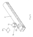
- Figures 5 and 6 show a unit 15 being lowered into the shell via an opening in the roof construction of the shell. It is possible to move units 15 that have slightly larger dimensions than normal into the shell via an opening 22, which is then closed by a roof element 21. Alternatively the entire roof can be removed for allowing units to be lowered into place ( Figure 6). In this case the dimensions of the available opening 23 will be almost the same as the dimensions of the roof element 4. This is a particularly convenient method of operation if it is necessary to equip the carriage with units which are different from normal sized units 15. As an example reference should be made to unit 15a, which is fitted with an extension wall 15b, by means of which the passenger compartment of the carriage can be divided into different sections.
- Figure 7 shows a unit 15 divided into segments 26.
- the opening 24 can be smaller than the opening 22 in Figure 5 and the closing element 25 will be similarly smaller than the closing element 21.
- FIGS 8 and 9 illustrate a prefabricated self-supporting bottomless sleeping compartment unit 15 with its WC-module 16.
- the compartment unit 15 has a front wall E, side walls 5, and back wall T, a bed 27, a table 28 and a wardrobe 29.
- a basin 30 and a WC 31 are fitted with its own connections for services.
- Figure 10 shows a method of producing a unit 15 from prefabricated elements 16, 32-35.
- the front wall 35 is provided with an opening fitted with a door 36.
- the rear wall 34 is provided with a window opening and side walls are provided to bridge between the front and rear walls and the rear wall and the module 16.
- At the bottom of each wall 33, 34 and 35 is a supporting strip 37.
- a top wall 32 closes the unit from above.
- the strip 37 can serve to seal any gap left between a unit and the floor 19, e.g. after the unit has been moved into the precise position required from within the walls 33, 34, 35.
- Figure 11 shows how the services of the units 15 can be connected to those of the shell.
- the air conditioning pipe 9 is shown connected to piping 40 in the shell in the upper part of a carriage 39, and the water pipe 17 and drainage pipe 18 are shown connected to pipes below the floor 19.
Landscapes
- Engineering & Computer Science (AREA)
- Mechanical Engineering (AREA)
- Transportation (AREA)
- Life Sciences & Earth Sciences (AREA)
- Wood Science & Technology (AREA)
- Health & Medical Sciences (AREA)
- Epidemiology (AREA)
- General Health & Medical Sciences (AREA)
- Public Health (AREA)
- Residential Or Office Buildings (AREA)
Applications Claiming Priority (2)
| Application Number | Priority Date | Filing Date | Title |
|---|---|---|---|
| FI884317 | 1988-09-21 | ||
| FI884317A FI82422C (fi) | 1988-09-21 | 1988-09-21 | Sjaelvbaerande konstruktion. |
Publications (3)
| Publication Number | Publication Date |
|---|---|
| EP0360585A2 true EP0360585A2 (de) | 1990-03-28 |
| EP0360585A3 EP0360585A3 (en) | 1990-09-19 |
| EP0360585B1 EP0360585B1 (de) | 1995-02-15 |
Family
ID=8527064
Family Applications (1)
| Application Number | Title | Priority Date | Filing Date |
|---|---|---|---|
| EP89309563A Expired - Lifetime EP0360585B1 (de) | 1988-09-21 | 1989-09-20 | Schienenwagen und dessen Konstruktionsverfahren |
Country Status (3)
| Country | Link |
|---|---|
| EP (1) | EP0360585B1 (de) |
| DE (1) | DE68921127T2 (de) |
| FI (1) | FI82422C (de) |
Cited By (8)
| Publication number | Priority date | Publication date | Assignee | Title |
|---|---|---|---|---|
| EP0472176A1 (de) * | 1990-08-22 | 1992-02-26 | v. Cossel, Hans Detloff, Dr. | Sanitäreinheit für Eisenbahnwaggons |
| EP0489294A1 (de) * | 1990-12-05 | 1992-06-10 | Inventio Ag | Wagenkasten für Schienenfahrzeuge |
| US5233808A (en) * | 1990-06-19 | 1993-08-10 | Masa-Yards Oy | Method of constructing a building |
| EP0846606A1 (de) | 1996-12-05 | 1998-06-10 | Deutsche Waggonbau AG | Segmentierte Schalenbauweise mit schwimmend gelagerter Innenverkleidung |
| EP2189352A1 (de) * | 2008-11-19 | 2010-05-26 | Andrew Ashley-Smith | Gleisnetz, Eisenbahnwagen und Gleisanschluss |
| EP2562061A1 (de) * | 2011-08-25 | 2013-02-27 | Société Nationale des Chemins De Fer Français - SNCF | Schienenfahrzeug, das mit einem abnehmbaren Dach ausgestattet ist, und Verfahren zur Innenausstattung eines Schienenfahrzeugs |
| EP2705997A1 (de) * | 2012-09-11 | 2014-03-12 | Bombardier Transportation GmbH | Schienenfahrzeug mit einer Sanitärzelle, sowie Verfahren zur Herstellung einer Sanitärzelle für ein Schienenfahrzeug |
| US11731667B2 (en) | 2020-01-23 | 2023-08-22 | Speedinnov | Rail engine with technical equipment attachment device |
Families Citing this family (4)
| Publication number | Priority date | Publication date | Assignee | Title |
|---|---|---|---|---|
| DE19537498C2 (de) * | 1995-09-25 | 2002-01-31 | Dwa Deutsche Waggonbau Gmbh | Segmentierte Schalenbauweise mit schwimmend gelagerter Innenverkleidung |
| DE10110424A1 (de) † | 2001-03-05 | 2002-09-12 | Siemens Duewag Gmbh | Angetriebenes Schienenfahrzeug, insbesondere für die Personenbeförderung im Nah- und Regionalverkehr |
| DE102007007624B4 (de) | 2007-02-13 | 2008-10-30 | Maschinenbau Und Service Gmbh Ammendorf | Sanitär- bzw. WC-Modul, insbesondere für Fahrzeuge |
| DE102013208849B4 (de) * | 2013-05-14 | 2020-10-08 | Siemens Mobility GmbH | Fahrwerkloser Fahrzeugbrückenkasten |
Family Cites Families (3)
| Publication number | Priority date | Publication date | Assignee | Title |
|---|---|---|---|---|
| NL207956A (de) * | 1955-06-14 | |||
| FR1129713A (fr) * | 1955-08-05 | 1957-01-24 | Atel Const Nord De La France | Nouvelle voiture de chemin de fer |
| JPH0741832B2 (ja) * | 1987-03-02 | 1995-05-10 | 株式会社日立製作所 | モノレ−ル車両の車体下部構造 |
-
1988
- 1988-09-21 FI FI884317A patent/FI82422C/fi not_active IP Right Cessation
-
1989
- 1989-09-20 EP EP89309563A patent/EP0360585B1/de not_active Expired - Lifetime
- 1989-09-20 DE DE68921127T patent/DE68921127T2/de not_active Expired - Fee Related
Cited By (10)
| Publication number | Priority date | Publication date | Assignee | Title |
|---|---|---|---|---|
| US5233808A (en) * | 1990-06-19 | 1993-08-10 | Masa-Yards Oy | Method of constructing a building |
| EP0472176A1 (de) * | 1990-08-22 | 1992-02-26 | v. Cossel, Hans Detloff, Dr. | Sanitäreinheit für Eisenbahnwaggons |
| EP0489294A1 (de) * | 1990-12-05 | 1992-06-10 | Inventio Ag | Wagenkasten für Schienenfahrzeuge |
| EP0846606A1 (de) | 1996-12-05 | 1998-06-10 | Deutsche Waggonbau AG | Segmentierte Schalenbauweise mit schwimmend gelagerter Innenverkleidung |
| EP2189352A1 (de) * | 2008-11-19 | 2010-05-26 | Andrew Ashley-Smith | Gleisnetz, Eisenbahnwagen und Gleisanschluss |
| GB2465443B (en) * | 2008-11-19 | 2011-07-27 | Andrew Ashley-Smith | A railway system, a railway carriage and a railway siding |
| EP2562061A1 (de) * | 2011-08-25 | 2013-02-27 | Société Nationale des Chemins De Fer Français - SNCF | Schienenfahrzeug, das mit einem abnehmbaren Dach ausgestattet ist, und Verfahren zur Innenausstattung eines Schienenfahrzeugs |
| FR2979317A1 (fr) * | 2011-08-25 | 2013-03-01 | Sncf | Vehicule ferroviaire comportant un capot de toit amovible et procede d'amenagement interieur d'un vehicule ferroviaire |
| EP2705997A1 (de) * | 2012-09-11 | 2014-03-12 | Bombardier Transportation GmbH | Schienenfahrzeug mit einer Sanitärzelle, sowie Verfahren zur Herstellung einer Sanitärzelle für ein Schienenfahrzeug |
| US11731667B2 (en) | 2020-01-23 | 2023-08-22 | Speedinnov | Rail engine with technical equipment attachment device |
Also Published As
| Publication number | Publication date |
|---|---|
| DE68921127D1 (de) | 1995-03-23 |
| FI82422C (fi) | 1991-03-11 |
| EP0360585B1 (de) | 1995-02-15 |
| FI82422B (fi) | 1990-11-30 |
| EP0360585A3 (en) | 1990-09-19 |
| DE68921127T2 (de) | 1995-10-12 |
| FI884317A0 (fi) | 1988-09-21 |
| FI884317A7 (fi) | 1990-03-22 |
Similar Documents
| Publication | Publication Date | Title |
|---|---|---|
| EP0360585B1 (de) | Schienenwagen und dessen Konstruktionsverfahren | |
| US4594817A (en) | Modular sleeping units | |
| US5761797A (en) | Process for constructing a switchgear cabinet and for installing interior components | |
| US4010579A (en) | Three dimensional pre-fabricated structural elements for building habitation units | |
| RU2068368C1 (ru) | Кабинный судовой блок и способ его установки | |
| WO1994005879A1 (en) | Transportable dwelling unit | |
| CZ297048B6 (cs) | Pojízdná pohrební sín | |
| WO1997026153A1 (en) | Sanitary cell | |
| WO2008143496A1 (en) | Room unit, building comprising such a room unit, use of such a room unit as well as method of building a hotel | |
| US4827379A (en) | Electrical facility | |
| DK2031152T3 (en) | MODULAR sanitary SYSTEM | |
| US2469752A (en) | Portable housing unit | |
| JPH0342211Y2 (de) | ||
| CZ291223B6 (cs) | Chodbový kontejner | |
| JPH08216995A (ja) | 船舶の居室における空調システム | |
| KR20080066053A (ko) | 운송수단내부에 위치한 수용공간들의 배열 | |
| JP2683987B2 (ja) | 衛生設備室の構築方法 | |
| JPS6227221B2 (de) | ||
| CN218509133U (zh) | 内外科诊疗方舱 | |
| JPS5822726Y2 (ja) | 手術室における各種設備機器の取付装置 | |
| JPH11190082A (ja) | 快適性・個性化を考慮した集合住宅 | |
| GB2287486A (en) | An enclosed structure, e.g. Steam Room | |
| JPH0447533Y2 (de) | ||
| JPS6059386B2 (ja) | 組立式手術室 | |
| JP2002174042A (ja) | スケルトン・インフィル集合住宅 |
Legal Events
| Date | Code | Title | Description |
|---|---|---|---|
| PUAI | Public reference made under article 153(3) epc to a published international application that has entered the european phase |
Free format text: ORIGINAL CODE: 0009012 |
|
| AK | Designated contracting states |
Kind code of ref document: A2 Designated state(s): DE FR GB IT SE |
|
| PUAL | Search report despatched |
Free format text: ORIGINAL CODE: 0009013 |
|
| AK | Designated contracting states |
Kind code of ref document: A3 Designated state(s): DE FR GB IT SE |
|
| 17P | Request for examination filed |
Effective date: 19901215 |
|
| RAP1 | Party data changed (applicant data changed or rights of an application transferred) |
Owner name: MASA-YARDS OY |
|
| 17Q | First examination report despatched |
Effective date: 19830513 |
|
| GRAA | (expected) grant |
Free format text: ORIGINAL CODE: 0009210 |
|
| AK | Designated contracting states |
Kind code of ref document: B1 Designated state(s): DE FR GB IT SE |
|
| REF | Corresponds to: |
Ref document number: 68921127 Country of ref document: DE Date of ref document: 19950323 |
|
| ITF | It: translation for a ep patent filed | ||
| ET | Fr: translation filed | ||
| PGFP | Annual fee paid to national office [announced via postgrant information from national office to epo] |
Ref country code: FR Payment date: 19950803 Year of fee payment: 7 |
|
| PGFP | Annual fee paid to national office [announced via postgrant information from national office to epo] |
Ref country code: SE Payment date: 19950814 Year of fee payment: 7 |
|
| PGFP | Annual fee paid to national office [announced via postgrant information from national office to epo] |
Ref country code: GB Payment date: 19950815 Year of fee payment: 7 |
|
| PGFP | Annual fee paid to national office [announced via postgrant information from national office to epo] |
Ref country code: DE Payment date: 19950823 Year of fee payment: 7 |
|
| PLBE | No opposition filed within time limit |
Free format text: ORIGINAL CODE: 0009261 |
|
| STAA | Information on the status of an ep patent application or granted ep patent |
Free format text: STATUS: NO OPPOSITION FILED WITHIN TIME LIMIT |
|
| 26N | No opposition filed | ||
| PG25 | Lapsed in a contracting state [announced via postgrant information from national office to epo] |
Ref country code: GB Effective date: 19960920 |
|
| PG25 | Lapsed in a contracting state [announced via postgrant information from national office to epo] |
Ref country code: SE Effective date: 19960921 |
|
| PG25 | Lapsed in a contracting state [announced via postgrant information from national office to epo] |
Ref country code: FR Effective date: 19960930 |
|
| GBPC | Gb: european patent ceased through non-payment of renewal fee |
Effective date: 19960920 |
|
| PG25 | Lapsed in a contracting state [announced via postgrant information from national office to epo] |
Ref country code: DE Effective date: 19970603 |
|
| EUG | Se: european patent has lapsed |
Ref document number: 89309563.8 |
|
| REG | Reference to a national code |
Ref country code: FR Ref legal event code: ST |
|
| REG | Reference to a national code |
Ref country code: FR Ref legal event code: ST |
|
| PG25 | Lapsed in a contracting state [announced via postgrant information from national office to epo] |
Ref country code: IT Free format text: LAPSE BECAUSE OF NON-PAYMENT OF DUE FEES;WARNING: LAPSES OF ITALIAN PATENTS WITH EFFECTIVE DATE BEFORE 2007 MAY HAVE OCCURRED AT ANY TIME BEFORE 2007. THE CORRECT EFFECTIVE DATE MAY BE DIFFERENT FROM THE ONE RECORDED. Effective date: 20050920 |