EP0360767A1 - Unité d'agitation à entraînement magnétique - Google Patents
Unité d'agitation à entraînement magnétique Download PDFInfo
- Publication number
- EP0360767A1 EP0360767A1 EP89830408A EP89830408A EP0360767A1 EP 0360767 A1 EP0360767 A1 EP 0360767A1 EP 89830408 A EP89830408 A EP 89830408A EP 89830408 A EP89830408 A EP 89830408A EP 0360767 A1 EP0360767 A1 EP 0360767A1
- Authority
- EP
- European Patent Office
- Prior art keywords
- stirring
- unit according
- stirring unit
- flanged plate
- stirring element
- Prior art date
- Legal status (The legal status is an assumption and is not a legal conclusion. Google has not performed a legal analysis and makes no representation as to the accuracy of the status listed.)
- Withdrawn
Links
- 238000003756 stirring Methods 0.000 title claims abstract description 54
- 238000012423 maintenance Methods 0.000 claims abstract description 5
- 239000012530 fluid Substances 0.000 claims description 2
- 208000034809 Product contamination Diseases 0.000 abstract description 3
- 239000007788 liquid Substances 0.000 abstract 1
- 239000012265 solid product Substances 0.000 abstract 1
- 239000000463 material Substances 0.000 description 3
- 238000004140 cleaning Methods 0.000 description 2
- 238000004519 manufacturing process Methods 0.000 description 2
- 230000005540 biological transmission Effects 0.000 description 1
- 238000010276 construction Methods 0.000 description 1
- 230000008878 coupling Effects 0.000 description 1
- 238000010168 coupling process Methods 0.000 description 1
- 238000005859 coupling reaction Methods 0.000 description 1
- 238000012986 modification Methods 0.000 description 1
- 230000004048 modification Effects 0.000 description 1
- 238000013021 overheating Methods 0.000 description 1
- 230000002093 peripheral effect Effects 0.000 description 1
- 238000005096 rolling process Methods 0.000 description 1
- 238000007789 sealing Methods 0.000 description 1
- 230000003068 static effect Effects 0.000 description 1
- 230000001954 sterilising effect Effects 0.000 description 1
- 238000004659 sterilization and disinfection Methods 0.000 description 1
- 239000000126 substance Substances 0.000 description 1
- 238000003466 welding Methods 0.000 description 1
Images
Classifications
-
- B—PERFORMING OPERATIONS; TRANSPORTING
- B01—PHYSICAL OR CHEMICAL PROCESSES OR APPARATUS IN GENERAL
- B01F—MIXING, e.g. DISSOLVING, EMULSIFYING OR DISPERSING
- B01F33/00—Other mixers; Mixing plants; Combinations of mixers
- B01F33/45—Magnetic mixers; Mixers with magnetically driven stirrers
- B01F33/453—Magnetic mixers; Mixers with magnetically driven stirrers using supported or suspended stirring elements
- B01F33/4535—Magnetic mixers; Mixers with magnetically driven stirrers using supported or suspended stirring elements using a stud for supporting the stirring element
-
- B—PERFORMING OPERATIONS; TRANSPORTING
- B01—PHYSICAL OR CHEMICAL PROCESSES OR APPARATUS IN GENERAL
- B01F—MIXING, e.g. DISSOLVING, EMULSIFYING OR DISPERSING
- B01F35/00—Accessories for mixers; Auxiliary operations or auxiliary devices; Parts or details of general application
- B01F35/10—Maintenance of mixers
-
- B—PERFORMING OPERATIONS; TRANSPORTING
- B01—PHYSICAL OR CHEMICAL PROCESSES OR APPARATUS IN GENERAL
- B01F—MIXING, e.g. DISSOLVING, EMULSIFYING OR DISPERSING
- B01F35/00—Accessories for mixers; Auxiliary operations or auxiliary devices; Parts or details of general application
- B01F35/40—Mounting or supporting mixing devices or receptacles; Clamping or holding arrangements therefor
- B01F35/41—Mounting or supporting stirrer shafts or stirrer units on receptacles
- B01F35/411—Mounting or supporting stirrer shafts or stirrer units on receptacles by supporting only one extremity of the shaft
- B01F35/4112—Mounting or supporting stirrer shafts or stirrer units on receptacles by supporting only one extremity of the shaft at the bottom of the receptacle, e.g. by studs
Definitions
- the present invention refers to the field of the industrial mixing equipments with particular, even if not exclusive, reference to the chemical and pharmaceutical field, and, more precisely, concerns a magnetic drive stirring unit.
- the stirring equipments known in the art comprise a stirring element, whose design and construction varies according to the uses, integral to a supported shaft, usually on rolling bearings, placed outside the container, which holds the product to be mixed.
- Mechanical seals are arranged between the shaft and the container in order to prevent, or at least to limit, the environment pollution and/or the product contamination.
- Magnetic drive stirring units essentially used in laboratory vessels and small scale plants, are also well known in the art. These stirring units assure the best seal conditions required in most appliances, because they comprise a stirring element inside the vessel magnetically coupled to an outer driving device without any mutual mechanical joint as well as mechanical seals.
- Another object of the present invention is to provide a magnetic drive stirring unit capable of being easily and rapidly installed on the container and without significant maintenance problems.
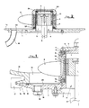
- the novel feature of the magnetic drive stirring unit according to the invention consists in that it comprises a flanged plate seal mountable in correspondence with a bottom opening of the vessel containing the product to be mixed, from said flanged plate centrally extending a tubular casing on which a stirring element is pivotally mounted, while the driving device is installed inside said tubular casing, in coaxial relation with the stirring element and the container, and is supported by said flanged plate.
- the stirring element is supported on friction bearings.
- the flanged plate is fixed to a corresponding counterflange of the container by means of a rapid lock connection engaging with two tapered surfaces correspondingly formed on said flanged plate and said counterflange.
- a flanged plate preferably of circular shape, from the central part of which a tubular casing 2 extends upwardly, whose free end is closed by a wall 3.
- a driving unit able to produce a rotating magnetic field, is housed within the tubular casing 2, that has a cylindrical shape.
- the driving unit 4 consists of a shaft 5, to the end of which a magnet 6 is keyed.
- the shaft 5 is supported by bearings, not shown, housed within a bracket 7 fixed to the plate 1.
- a stirring element 8 for instance a propeller, radially extends from an annular support body 9 that is pivotally mounted on the outer side of tubular casing 2 in a coaxial relation with shaft 5. Within the annular body 9 there is mounted a second magnet 10 of annular shape driven in rotation by the rotating magnet 6.
- Annular body 9 rotates by sliding on side cylindrical surface of tubular casing 2, friction bearing means being provided therebetween.
- the friction bearing means comprises a pair of substantially L-shaped rings 11, fixed to the outer side of tubular casing 2 in correspondence with the base and, respectively the free end thereof, and a pair of squared section rings 12 correspondingly fixed to the ends of annular body 9 with a face frictionally contacting a corresponding face of L-shaped rings 11.
- Rings 11 and 12 are made of a material that does not exhibit overheating during the use and compatible with the product to be mixed; the most suitable material for each case can be easily chosen by a person skilled in the art.
- the above described stirring unit is set in correspondence with opening 13, formed in the bottom of a vessel or container 14, in order that the tubular casing 2 results inside the container 14 itself.
- the bottom opening 13 is provided with a counterflange 15 matching the flange 1a of the plate 1 by interposition of a sealing member, for instance an o-ring 16.
- the coupling between the flange 1a and the counterflange 15 is firmly assured by a rapid lock connection 17, for instance a jaw connection, as schematically shown in figure 1.
- the outer faces of the flange 1a and of the counterflange 15 are tapered and converging, giving rise altogether to a frustum of cone surface with which the correspondingly shaped rapid lock connection 17 can be firmly engaged.
- a through hole 18, normally plugged by a cap 19 is formed in the plate 1, and a large conic hollow 20 is formed on the internal surface of the plate 1 in order to make easier the drainage of the product.
- the stirring element 8 may be of the blade type or a propeller, or it may have any other shape chosen by the designer as a function of the kind of material to be mixed.
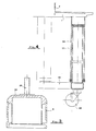
- FIG. 2 A simplified structure of the stirring unit according to the invention is shown in the embodiment of Figure 2.
- the tubular casing 2 is fixed, for example by means of welding, to the flanged plate 1
- the annular body 9, which supports the propeller 8 is fixed to a bell-shaped support 23, coaxially arranged over the tubular casing 2.
- Support 23, which houses the magnetic element or rotor 9, is magnetically driven into rotation around the tubular casing 2, frictional bearing means being provided comprising two rings 21 and 22.
- the first ring 21 is housed in a peripheral seat of the plate 3, while the second ring 22 is housed in a seat formed at the base of the tubular casing 2.
- the bell-shaped support 23 may be provided with a screw threaded pivot 24 outwardly extending above it so that a lot of different types of propellers, as far as diameter and shape are concerned, can be mounted on it so as to get the best performance of the stirring unit with every kind of fluid to be mixed.
- the stirring unit according to the present invention may advantageously be equipped with a supporting device suitable to make easier the removal of the unit, as schematically shown in figure 4.
- the supporting device substantially comprises a base 25, preferably mounted on wheels 26 and tubular rod 27 extending vertically therefrom and housed within corresponding cylinders 28 and suitable to mutually slide by means of pneumatic actuation or the like. In this way the stirring unit, once disconnected from the container, may easily be lowered and moved.
- the magnetic drive stirring unit according to the present invention allows to get significant advantages in comparison with the mechanic drive stirring units presently known.
Landscapes
- Chemical & Material Sciences (AREA)
- Chemical Kinetics & Catalysis (AREA)
- Mixers With Rotating Receptacles And Mixers With Vibration Mechanisms (AREA)
- Accessories For Mixers (AREA)
Applications Claiming Priority (2)
| Application Number | Priority Date | Filing Date | Title |
|---|---|---|---|
| IT8809490A IT1225238B (it) | 1988-09-23 | 1988-09-23 | Gruppo di agitazione a trascinamento magnetico |
| IT949088 | 1988-09-23 |
Publications (1)
| Publication Number | Publication Date |
|---|---|
| EP0360767A1 true EP0360767A1 (fr) | 1990-03-28 |
Family
ID=11130909
Family Applications (1)
| Application Number | Title | Priority Date | Filing Date |
|---|---|---|---|
| EP89830408A Withdrawn EP0360767A1 (fr) | 1988-09-23 | 1989-09-21 | Unité d'agitation à entraînement magnétique |
Country Status (2)
| Country | Link |
|---|---|
| EP (1) | EP0360767A1 (fr) |
| IT (1) | IT1225238B (fr) |
Cited By (11)
| Publication number | Priority date | Publication date | Assignee | Title |
|---|---|---|---|---|
| EP0599010A1 (fr) * | 1992-10-01 | 1994-06-01 | Mavag Verfahrenstechnik Ag | Agitateur double pour remuer des liquides steriles |
| US5478149A (en) * | 1995-04-24 | 1995-12-26 | Magnetic Mixers, Inc. | Magnetic mixer |
| US5758965A (en) * | 1996-12-05 | 1998-06-02 | General Signal Corporation | Mixer system |
| US5779359A (en) * | 1996-12-05 | 1998-07-14 | General Signal Corporation | Mixer having exposed clean-in-place bearing assemblies |
| US6065865A (en) * | 1998-06-05 | 2000-05-23 | Mixel | Magnetically driven agitator with magnetic rotation detector |
| US6206562B1 (en) * | 1998-01-28 | 2001-03-27 | Mixel | Agitator with adjustable magnetic drive coupling |
| DE10318599A1 (de) * | 2003-04-24 | 2004-11-11 | Mavag Verfahrenstechnik Ag | Rührer zum Mischen, Homogenisieren und Dispergieren |
| CN109843424A (zh) * | 2016-08-01 | 2019-06-04 | 捷特有限公司 | 模块化搅拌机构 |
| IT201900019172A1 (it) * | 2019-10-17 | 2020-01-17 | Paolo Stemberger | Agitatore elettromagnetico perfezionato |
| CN112871045A (zh) * | 2021-01-18 | 2021-06-01 | 乐锐 | 一种分层搅拌混合机 |
| CN114588849A (zh) * | 2022-02-22 | 2022-06-07 | 兰州城市学院 | 一种水热法制备3d纳米花复合材料的方法 |
Citations (6)
| Publication number | Priority date | Publication date | Assignee | Title |
|---|---|---|---|---|
| US2495895A (en) * | 1945-10-31 | 1950-01-31 | Universal Oil Prod Co | Fluid circulating device |
| US2506886A (en) * | 1948-04-19 | 1950-05-09 | Automatic Magnetic Agitators L | Magnetic drive agitator |
| US2810556A (en) * | 1955-03-14 | 1957-10-22 | Tormag Transmissions Ltd | Agitators for fluid cooling tanks and the like |
| DE1294936B (de) * | 1964-03-03 | 1969-05-14 | Teikoku Denki Seisakusho Kk | Ruehrvorrichtung |
| FR2164837A1 (fr) * | 1971-12-22 | 1973-08-03 | Nippon Steel Corp | |
| GB2185862A (en) * | 1985-12-11 | 1987-07-29 | Chem Plant Stainless Limited | Mixing vessel |
-
1988
- 1988-09-23 IT IT8809490A patent/IT1225238B/it active
-
1989
- 1989-09-21 EP EP89830408A patent/EP0360767A1/fr not_active Withdrawn
Patent Citations (6)
| Publication number | Priority date | Publication date | Assignee | Title |
|---|---|---|---|---|
| US2495895A (en) * | 1945-10-31 | 1950-01-31 | Universal Oil Prod Co | Fluid circulating device |
| US2506886A (en) * | 1948-04-19 | 1950-05-09 | Automatic Magnetic Agitators L | Magnetic drive agitator |
| US2810556A (en) * | 1955-03-14 | 1957-10-22 | Tormag Transmissions Ltd | Agitators for fluid cooling tanks and the like |
| DE1294936B (de) * | 1964-03-03 | 1969-05-14 | Teikoku Denki Seisakusho Kk | Ruehrvorrichtung |
| FR2164837A1 (fr) * | 1971-12-22 | 1973-08-03 | Nippon Steel Corp | |
| GB2185862A (en) * | 1985-12-11 | 1987-07-29 | Chem Plant Stainless Limited | Mixing vessel |
Cited By (12)
| Publication number | Priority date | Publication date | Assignee | Title |
|---|---|---|---|---|
| EP0599010A1 (fr) * | 1992-10-01 | 1994-06-01 | Mavag Verfahrenstechnik Ag | Agitateur double pour remuer des liquides steriles |
| US5407272A (en) * | 1992-10-01 | 1995-04-18 | Mavag Verfahrenstechnik Ag. | Double impeller for stirring sterile liquids |
| US5478149A (en) * | 1995-04-24 | 1995-12-26 | Magnetic Mixers, Inc. | Magnetic mixer |
| US5758965A (en) * | 1996-12-05 | 1998-06-02 | General Signal Corporation | Mixer system |
| US5779359A (en) * | 1996-12-05 | 1998-07-14 | General Signal Corporation | Mixer having exposed clean-in-place bearing assemblies |
| US6206562B1 (en) * | 1998-01-28 | 2001-03-27 | Mixel | Agitator with adjustable magnetic drive coupling |
| US6065865A (en) * | 1998-06-05 | 2000-05-23 | Mixel | Magnetically driven agitator with magnetic rotation detector |
| DE10318599A1 (de) * | 2003-04-24 | 2004-11-11 | Mavag Verfahrenstechnik Ag | Rührer zum Mischen, Homogenisieren und Dispergieren |
| CN109843424A (zh) * | 2016-08-01 | 2019-06-04 | 捷特有限公司 | 模块化搅拌机构 |
| IT201900019172A1 (it) * | 2019-10-17 | 2020-01-17 | Paolo Stemberger | Agitatore elettromagnetico perfezionato |
| CN112871045A (zh) * | 2021-01-18 | 2021-06-01 | 乐锐 | 一种分层搅拌混合机 |
| CN114588849A (zh) * | 2022-02-22 | 2022-06-07 | 兰州城市学院 | 一种水热法制备3d纳米花复合材料的方法 |
Also Published As
| Publication number | Publication date |
|---|---|
| IT1225238B (it) | 1990-11-02 |
| IT8809490A0 (it) | 1988-09-23 |
Similar Documents
| Publication | Publication Date | Title |
|---|---|---|
| US6206562B1 (en) | Agitator with adjustable magnetic drive coupling | |
| EP0360767A1 (fr) | Unité d'agitation à entraînement magnétique | |
| CA2621588C (fr) | Procede et dispositif de melange a usage unique pour applications sanitaires | |
| US3572651A (en) | Spin-culture flask for cell culture | |
| US9669368B2 (en) | Device for stirring | |
| US7396153B2 (en) | Ultraclean magnetic mixer | |
| JP5143737B2 (ja) | 磁気シール組立体 | |
| WO2014116165A1 (fr) | Système de mélange avec agitateur magnétique et support pour mélange avec agitateur | |
| CN201127887Y (zh) | 一种磁力搅拌器 | |
| EP0590472A1 (fr) | Mélangeur magnétique | |
| JPH0380530B2 (fr) | ||
| CN108339482A (zh) | 用于搅拌器容器的搅拌器 | |
| EP1693121A1 (fr) | Dispositif d'entrainement pour un mélangeur et méthode de nettoyage | |
| FI90732B (fi) | Sekoitin | |
| US3602486A (en) | Device for stirring material or drying slurries or sludges | |
| US4668099A (en) | Conical spiral mixer with spherical sealing body in the bottom opening | |
| US20060099028A1 (en) | Coupling assembly and method for connecting and disconnecting a shaft assembly | |
| GB2185862A (en) | Mixing vessel | |
| CN110732255A (zh) | 危废物料搅拌机 | |
| JPH0663129U (ja) | 攪拌装置 | |
| EP0822000A1 (fr) | Appareil d'agitation pour collecter des pigments principales utilisés pour la fabrication de peintures | |
| JPH078331B2 (ja) | 攪拌装置 | |
| US2516918A (en) | Submersible bearing construction | |
| CN221471642U (zh) | 上磁力搅拌器 | |
| CN209155572U (zh) | 一种分段式搅拌轴 |
Legal Events
| Date | Code | Title | Description |
|---|---|---|---|
| PUAI | Public reference made under article 153(3) epc to a published international application that has entered the european phase |
Free format text: ORIGINAL CODE: 0009012 |
|
| AK | Designated contracting states |
Kind code of ref document: A1 Designated state(s): AT CH DE FR GB LI NL |
|
| 17P | Request for examination filed |
Effective date: 19900831 |
|
| 17Q | First examination report despatched |
Effective date: 19920409 |
|
| STAA | Information on the status of an ep patent application or granted ep patent |
Free format text: STATUS: THE APPLICATION HAS BEEN WITHDRAWN |
|
| 18W | Application withdrawn |
Withdrawal date: 19920615 |