EP0360779B2 - Vorrichtung zum Abbremsen von Elektromotoren - Google Patents
Vorrichtung zum Abbremsen von Elektromotoren Download PDFInfo
- Publication number
- EP0360779B2 EP0360779B2 EP89890200A EP89890200A EP0360779B2 EP 0360779 B2 EP0360779 B2 EP 0360779B2 EP 89890200 A EP89890200 A EP 89890200A EP 89890200 A EP89890200 A EP 89890200A EP 0360779 B2 EP0360779 B2 EP 0360779B2
- Authority
- EP
- European Patent Office
- Prior art keywords
- squirrel
- brake body
- cage rotor
- projections
- short
- Prior art date
- Legal status (The legal status is an assumption and is not a legal conclusion. Google has not performed a legal analysis and makes no representation as to the accuracy of the status listed.)
- Expired - Lifetime
Links
- 238000003466 welding Methods 0.000 claims description 2
- 239000007779 soft material Substances 0.000 claims 1
- 238000000034 method Methods 0.000 abstract description 3
- 239000002184 metal Substances 0.000 abstract description 2
- 238000013459 approach Methods 0.000 description 3
- 238000004519 manufacturing process Methods 0.000 description 1
- 239000007787 solid Substances 0.000 description 1
Images


Classifications
-
- H—ELECTRICITY
- H02—GENERATION; CONVERSION OR DISTRIBUTION OF ELECTRIC POWER
- H02K—DYNAMO-ELECTRIC MACHINES
- H02K7/00—Arrangements for handling mechanical energy structurally associated with dynamo-electric machines, e.g. structural association with mechanical driving motors or auxiliary dynamo-electric machines
- H02K7/10—Structural association with clutches, brakes, gears, pulleys or mechanical starters
- H02K7/102—Structural association with clutches, brakes, gears, pulleys or mechanical starters with friction brakes
- H02K7/1021—Magnetically influenced friction brakes
- H02K7/1026—Magnetically influenced friction brakes using stray fields
- H02K7/1028—Magnetically influenced friction brakes using stray fields axially attracting the brake armature in the frontal area of the magnetic core
Definitions
- the invention relates to a device for braking of electric motors with short-circuit rotors, having the features of the introductory part of claim 1.
- Such a device for braking of electric motors is from EP-B1 136 282 known.
- the one described in this patent The device preferably uses brake bodies made of deep-drawn sheet metal.
- a brake body is known from US Pat. No. 3,032,667 known that is cast or machined can be.
- the brake body is over one tubular part guided on the rotor shaft and lies over one end of the tubular part Rotor on.
- the object of the invention is a device of the type mentioned at the outset, that the disadvantages mentioned in the deep-drawing process manufactured brake bodies in a simple manner be avoided.
- the sleeve on the brake body becomes an easy to manufacture precisely defined contact surface of the brake body created on the rotor package.
- a very simple and solid attachment option the sleeve on the brake body results from that the sleeve by welding to the floor the brake body is attached.
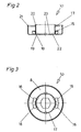
- FIG. 1 shows in section one with the inventive Device equipped, asynchronous Motor with squirrel-cage rotor, Fig. 2 and Fig. 3 shows an embodiment of the brake body and 4 shows the squirrel-cage rotor of the motor from FIG. 1 in oblique view.
- the asynchronous squirrel-cage motor shown in FIG. 1 consists of a stator 1 and a Short-circuit rotor 2 with a short-circuit ring 13, whose shaft 3 is rotatable in end shields 4 and 5 is stored.
- FIG. 1 is the left end of the shaft 3 in FIG a brake body 6 inserted.
- a sleeve 17 is arranged, e.g. by welds 19 on the bottom 8 of the brake body 6 is attached.
- the sleeve 17 is advantageously on the radially inward facing surfaces 18 of the projections 15. It can also between the surface 18 of the projections 15 and the sleeve 17 - as in the drawings shown - be a small gap.
- At the Bottom 8 of the brake body 6 faces the sleeve 17 an annular extension 22 towards the inside, against whose surface 23 the spring 11 is supported. At the same time, the spring 11 by the Inner surface of the sleeve 17 out.
- the sleeve 17 With its in a normal plane to the axis of rotation of the short-circuit rotor 2 lying end face 20th the sleeve 17 supports the brake body 6 against one within the short-circuit ring 13 on the squirrel-cage rotor 2 arranged, normal to the axis of rotation of the short-circuit rotor 2 lying surface 24, when the brake body 6 by the magnetic field is drawn against the squirrel-cage rotor 2.
- the unprocessed end 21 of the brake body 6 lies it is free and there is no contact of the end 21 with other parts of the engine.
- the power supply breaks down the magnetic field and the brake body 6 is from the Spring 11 against that shown in the shield 5 Brake pad 12 pressed.
- Through the sleeve 17 results there is also good axial guidance of the brake body 6 in the short-circuit ring 13 of the rotor 2.
Landscapes
- Engineering & Computer Science (AREA)
- Power Engineering (AREA)
- Connection Of Motors, Electrical Generators, Mechanical Devices, And The Like (AREA)
- Braking Arrangements (AREA)
- Control Of Multiple Motors (AREA)
- Stopping Of Electric Motors (AREA)
Description
Claims (6)
- Vorrichtung zum Abbremsen von Elektromotoren mit Kurzschlußläufern (2), mit einem im Tiefziehverfahren hergestellten, im wesentlichen topfförmigen Bremskörper (6), dessen freier Rand (21) zum Kurzschlußring (13) des Kurzschlußläufers (2) hinweist, der wenigstens teilweise aus weichmagnetischem Werkstoff besteht und der an zum Kurzschlußring (13) hinragenden Vorsprüngen (15) je mindestens eine Schrägfläche (16) aufweist, die am Kurzschlußring (13) des Kurzschlußläufers (2) angeordneten Vorsprüngen zugekehrt sind, welche Vorsprünge je eine Keilfläche (14) aufweisen, die zur Achse des Kurzschlußläufers (2) in der gleichen Schräglage wie die Schrägfläche (16) am Bremskörper (6) ausgerichtet ist, wobei zwischen dem Bremskörper (6) und einem gehäusefesten Bauteil (5) des Elektromotors ein Bremsbelag (12) und zwischen dem Bremskörper (6) und dem Kurzschlußläufer (2) eine den Bremskörper (6) gegen den Bremsbelag (12) drückende Feder (11) angeordnet ist, dadurch gekennzeichnet, daß am topfförmigen Bremskörper (6) eine zum Kurzschlußläufer (2) hin weisende, zylinderförmige, zum topfförmigen Bremskörper (6) koaxial angeordnete Hülse (17) befestigt ist, die an der radial innen liegenden Seite der Vorsprünge (15) anliegt, daß die Hülse (17) in der vom Magnetfeld zum Kurzschlußläufer (2) hin gezogenen Stellung des Bremskörpers (6) mit ihrer zum Kurzschlußläufer (2) hin weisenden Fläche (20) am Rotorpaket stirnseitig anliegt, und daß der freie Rand (21) des Bremskörpers (6) in dessen zum Kurzschlußläufer (2) hin gezogenen Stellung frei liegt und keine Teile des Motors berührt.
- Vorrichtung nach Anspruch 1, dadurch gekennzeichnet, daß am Boden (8) des Bremskörpers (6) ein radial innerhalb der Hülse (17) liegender kreisringförmiger Ansatz (22) gebildet ist, gegen dessen zum Kurzschlußläufer (2) hin weisende Fläche (23) sich die Feder (11) abstützt.
- Vorrichtung nach Anspruch 1 oder 2, dadurch gekennzeichnet, daß sich die Feder (11) gegen eine normal zur Drehachse des Kurzschlußläufers (2) liegende, zum Bremskörper (6) hin weisende, innerhalb des Kurzschlußringes (13) am Kurzschlußläufer (2) angeordnete Fläche (24) abstützt.
- Vorrichtung nach einem der Ansprüche 1 bis 3, dadurch gekennzeichnet, daß die Hülse (17) durch Schweißen am Boden (8) des Bremskörpers (6) befestigt ist.
- Vorrichtung nach einem der Ansprüche 1 bis 4, dadurch gekennzeichnet, daß am Kurzschlußring (13) teilringförmige Rippen (25) vorgesehen sind, die zwischen den die Keilflächen (14) aufweisenden Vorsprüngen angeordnet sind.
- Vorrichtung nach Anspruch 5, dadurch gekennzeichnet, daß die Rippe (25) mit den Vorsprüngen einstückig ausgebildet ist.
Applications Claiming Priority (2)
| Application Number | Priority Date | Filing Date | Title |
|---|---|---|---|
| AT2318/88 | 1988-09-21 | ||
| AT0231888A AT395361B (de) | 1988-09-21 | 1988-09-21 | Vorrichtung zum abbremsen von elektromotoren mit kurzschlusslaeufern |
Publications (4)
| Publication Number | Publication Date |
|---|---|
| EP0360779A2 EP0360779A2 (de) | 1990-03-28 |
| EP0360779A3 EP0360779A3 (en) | 1990-07-04 |
| EP0360779B1 EP0360779B1 (de) | 1993-10-13 |
| EP0360779B2 true EP0360779B2 (de) | 1998-02-11 |
Family
ID=3532149
Family Applications (1)
| Application Number | Title | Priority Date | Filing Date |
|---|---|---|---|
| EP89890200A Expired - Lifetime EP0360779B2 (de) | 1988-09-21 | 1989-07-28 | Vorrichtung zum Abbremsen von Elektromotoren |
Country Status (4)
| Country | Link |
|---|---|
| EP (1) | EP0360779B2 (de) |
| AT (2) | AT395361B (de) |
| DE (1) | DE58905901D1 (de) |
| ES (1) | ES2045562T5 (de) |
Families Citing this family (6)
| Publication number | Priority date | Publication date | Assignee | Title |
|---|---|---|---|---|
| DE4106897A1 (de) * | 1991-03-05 | 1992-09-10 | Licentia Gmbh | Elektromotor mit selbsttaetig wirkender bremse |
| DE4106914C2 (de) * | 1991-03-05 | 1993-12-16 | Licentia Gmbh | Elektromotor mit beim Abschalten des Motors selbsttätig wirkender Bremse |
| BG61889B1 (bg) * | 1996-09-30 | 1998-08-31 | Стаевски, Нанчо М. | Устройство за спиране на електродвигатели |
| AT408394B (de) | 1998-05-29 | 2001-11-26 | Atb Austria Antriebstech Ag | Vorrichtung zum abbremsen von elektromotoren |
| CN2583865Y (zh) * | 2002-12-16 | 2003-10-29 | 苏州宝时得电动工具有限公司 | 断电后自动刹车的电动机 |
| JP6472375B2 (ja) | 2015-12-25 | 2019-02-20 | ミネベアミツミ株式会社 | モータ |
Family Cites Families (5)
| Publication number | Priority date | Publication date | Assignee | Title |
|---|---|---|---|---|
| US3032667A (en) * | 1958-04-03 | 1962-05-01 | Manning Maxwell & Moore Inc | Motor brake |
| DE2751841C3 (de) * | 1977-11-19 | 1981-10-01 | G. Bauknecht Gmbh, 7000 Stuttgart | Kurzschlußläufermotor mit Reibungsbremse |
| AT378867B (de) * | 1983-08-31 | 1985-10-10 | Austria Antriebstech | Vorrichtung zum abbremsen von elektromotoren |
| DE3407731A1 (de) * | 1984-03-02 | 1985-09-05 | Licentia Patent-Verwaltungs-Gmbh, 6000 Frankfurt | Elektromotor mit automatisch wirkender bremse |
| DE8716775U1 (de) * | 1987-12-21 | 1988-09-01 | Robert Stahlschmidt Elektromotorenwerk GmbH, 4800 Bielefeld | Käfigläufermotor mit Federdruckbremse |
-
1988
- 1988-09-21 AT AT0231888A patent/AT395361B/de not_active IP Right Cessation
-
1989
- 1989-07-28 EP EP89890200A patent/EP0360779B2/de not_active Expired - Lifetime
- 1989-07-28 DE DE89890200T patent/DE58905901D1/de not_active Expired - Lifetime
- 1989-07-28 ES ES89890200T patent/ES2045562T5/es not_active Expired - Lifetime
- 1989-07-28 AT AT89890200T patent/ATE95956T1/de not_active IP Right Cessation
Also Published As
| Publication number | Publication date |
|---|---|
| DE58905901D1 (de) | 1993-11-18 |
| ES2045562T3 (es) | 1994-01-16 |
| EP0360779A2 (de) | 1990-03-28 |
| EP0360779A3 (en) | 1990-07-04 |
| ATE95956T1 (de) | 1993-10-15 |
| ES2045562T5 (es) | 1998-05-16 |
| AT395361B (de) | 1992-12-10 |
| ATA231888A (de) | 1992-04-15 |
| EP0360779B1 (de) | 1993-10-13 |
Similar Documents
| Publication | Publication Date | Title |
|---|---|---|
| DE3036091C2 (de) | Elektromotor mit selbsttätig wirkender Bremse | |
| DE3321444C2 (de) | ||
| DE60023782T2 (de) | Kleinstmotor und sein Herstellungsverfahren | |
| DE3327123A1 (de) | Antriebsanordnung fuer signalverarbeitende geraete | |
| EP0130344A1 (de) | Kupplungsmotor | |
| DE2155423C2 (de) | Kupplungsmotor | |
| EP0360779B2 (de) | Vorrichtung zum Abbremsen von Elektromotoren | |
| DE602004008514T2 (de) | Wälzlager und dasselbe verwendende motorvorrichtung | |
| DE2805687A1 (de) | Elektrische tauchmotoren | |
| EP0077032B1 (de) | Scheibenbremsmotor | |
| DE3400468A1 (de) | Wellenanordnung fuer einen verdichter | |
| DE6912018U (de) | Schraubenluefter, insbesondere fuer die elektronik. | |
| CH628474A5 (de) | Rotoranordnung fuer schrittschaltmotoren. | |
| DE3508227C1 (de) | Elektromagnetisch betaetigbare Reibungsbrems- und Kupplungsvorrichtung fuer einen elektromotorischen Antrieb,insbesondere fuer Industrie-Naehmaschinen | |
| EP1046215B1 (de) | Elektromotor-lüfterrad-kombination und verfahren zu deren herstellung | |
| DE102015001647B4 (de) | Bremsanordnung | |
| WO1986005028A1 (fr) | Aimant annulaire pour freins moteurs | |
| DE6910621U (de) | Elektromagnetisch betaetigter kupplungs-bremsmotor mit hohem traegheitsmoment | |
| DE10230006A1 (de) | Asynchronmaschine | |
| CH665063A5 (de) | Asynchronlaeufer. | |
| DE102006013536A1 (de) | Fluiddynamisches Lagersystem | |
| DE2751841B2 (de) | Kurzschlußläufermotor mit Reibungsbremse | |
| DE2635075C2 (de) | Klauenpolgenerator | |
| DE1538990B2 (de) | Zumindest teilweise topfartig aus Eisenblech gezogener Lagerschild fur einen Elektromotor | |
| DE102005008794A1 (de) | Elektromotorischer Antrieb |
Legal Events
| Date | Code | Title | Description |
|---|---|---|---|
| PUAI | Public reference made under article 153(3) epc to a published international application that has entered the european phase |
Free format text: ORIGINAL CODE: 0009012 |
|
| AK | Designated contracting states |
Kind code of ref document: A2 Designated state(s): AT BE CH DE ES FR GB IT LI LU NL SE |
|
| PUAL | Search report despatched |
Free format text: ORIGINAL CODE: 0009013 |
|
| AK | Designated contracting states |
Kind code of ref document: A3 Designated state(s): AT BE CH DE ES FR GB IT LI LU NL SE |
|
| 17P | Request for examination filed |
Effective date: 19900903 |
|
| 17Q | First examination report despatched |
Effective date: 19920901 |
|
| GRAA | (expected) grant |
Free format text: ORIGINAL CODE: 0009210 |
|
| AK | Designated contracting states |
Kind code of ref document: B1 Designated state(s): AT BE CH DE ES FR GB IT LI LU NL SE |
|
| REF | Corresponds to: |
Ref document number: 95956 Country of ref document: AT Date of ref document: 19931015 Kind code of ref document: T |
|
| ET | Fr: translation filed | ||
| REF | Corresponds to: |
Ref document number: 58905901 Country of ref document: DE Date of ref document: 19931118 |
|
| GBT | Gb: translation of ep patent filed (gb section 77(6)(a)/1977) |
Effective date: 19931026 |
|
| ITF | It: translation for a ep patent filed | ||
| REG | Reference to a national code |
Ref country code: ES Ref legal event code: FG2A Ref document number: 2045562 Country of ref document: ES Kind code of ref document: T3 |
|
| PLBI | Opposition filed |
Free format text: ORIGINAL CODE: 0009260 |
|
| 26 | Opposition filed |
Opponent name: NUOVA IBMEI S.P.A. Effective date: 19940706 |
|
| EPTA | Lu: last paid annual fee | ||
| NLR1 | Nl: opposition has been filed with the epo |
Opponent name: NUOVA IBMEI S.P.A. |
|
| EAL | Se: european patent in force in sweden |
Ref document number: 89890200.2 |
|
| PLAW | Interlocutory decision in opposition |
Free format text: ORIGINAL CODE: EPIDOS IDOP |
|
| PLAW | Interlocutory decision in opposition |
Free format text: ORIGINAL CODE: EPIDOS IDOP |
|
| PUAH | Patent maintained in amended form |
Free format text: ORIGINAL CODE: 0009272 |
|
| STAA | Information on the status of an ep patent application or granted ep patent |
Free format text: STATUS: PATENT MAINTAINED AS AMENDED |
|
| 27A | Patent maintained in amended form |
Effective date: 19980211 |
|
| AK | Designated contracting states |
Kind code of ref document: B2 Designated state(s): AT BE CH DE ES FR GB IT LI LU NL SE |
|
| ITF | It: translation for a ep patent filed | ||
| GBTA | Gb: translation of amended ep patent filed (gb section 77(6)(b)/1977) | ||
| ET3 | Fr: translation filed ** decision concerning opposition | ||
| REG | Reference to a national code |
Ref country code: CH Ref legal event code: AEN Free format text: AUFRECHTERHALTUNG DES PATENTES IN GEAENDERTER FORM |
|
| NLR2 | Nl: decision of opposition | ||
| NLR3 | Nl: receipt of modified translations in the netherlands language after an opposition procedure | ||
| REG | Reference to a national code |
Ref country code: ES Ref legal event code: DC2A Kind code of ref document: T5 Effective date: 19980414 |
|
| REG | Reference to a national code |
Ref country code: GB Ref legal event code: IF02 |
|
| PGFP | Annual fee paid to national office [announced via postgrant information from national office to epo] |
Ref country code: ES Payment date: 20080620 Year of fee payment: 20 |
|
| PGFP | Annual fee paid to national office [announced via postgrant information from national office to epo] |
Ref country code: LU Payment date: 20080710 Year of fee payment: 20 Ref country code: DE Payment date: 20080701 Year of fee payment: 20 Ref country code: CH Payment date: 20080924 Year of fee payment: 20 |
|
| PGFP | Annual fee paid to national office [announced via postgrant information from national office to epo] |
Ref country code: NL Payment date: 20080715 Year of fee payment: 20 Ref country code: AT Payment date: 20080723 Year of fee payment: 20 Ref country code: IT Payment date: 20080731 Year of fee payment: 20 Ref country code: FR Payment date: 20080718 Year of fee payment: 20 |
|
| PGFP | Annual fee paid to national office [announced via postgrant information from national office to epo] |
Ref country code: GB Payment date: 20080806 Year of fee payment: 20 |
|
| PGFP | Annual fee paid to national office [announced via postgrant information from national office to epo] |
Ref country code: BE Payment date: 20080701 Year of fee payment: 20 Ref country code: SE Payment date: 20080707 Year of fee payment: 20 |
|
| REG | Reference to a national code |
Ref country code: CH Ref legal event code: PL |
|
| REG | Reference to a national code |
Ref country code: GB Ref legal event code: PE20 Expiry date: 20090727 |
|
| EUG | Se: european patent has lapsed | ||
| REG | Reference to a national code |
Ref country code: ES Ref legal event code: FD2A Effective date: 20090729 |
|
| NLV7 | Nl: ceased due to reaching the maximum lifetime of a patent |
Effective date: 20090728 |
|
| PG25 | Lapsed in a contracting state [announced via postgrant information from national office to epo] |
Ref country code: ES Free format text: LAPSE BECAUSE OF EXPIRATION OF PROTECTION Effective date: 20090729 |
|
| PG25 | Lapsed in a contracting state [announced via postgrant information from national office to epo] |
Ref country code: NL Free format text: LAPSE BECAUSE OF EXPIRATION OF PROTECTION Effective date: 20090728 Ref country code: GB Free format text: LAPSE BECAUSE OF EXPIRATION OF PROTECTION Effective date: 20090727 |