EP0361011A2 - Dispositif indicateur pour une transmission automatique de véhicule - Google Patents
Dispositif indicateur pour une transmission automatique de véhicule Download PDFInfo
- Publication number
- EP0361011A2 EP0361011A2 EP89113533A EP89113533A EP0361011A2 EP 0361011 A2 EP0361011 A2 EP 0361011A2 EP 89113533 A EP89113533 A EP 89113533A EP 89113533 A EP89113533 A EP 89113533A EP 0361011 A2 EP0361011 A2 EP 0361011A2
- Authority
- EP
- European Patent Office
- Prior art keywords
- display device
- gear
- display elements
- display
- iii
- Prior art date
- Legal status (The legal status is an assumption and is not a legal conclusion. Google has not performed a legal analysis and makes no representation as to the accuracy of the status listed.)
- Granted
Links
Images

Classifications
-
- F—MECHANICAL ENGINEERING; LIGHTING; HEATING; WEAPONS; BLASTING
- F16—ENGINEERING ELEMENTS AND UNITS; GENERAL MEASURES FOR PRODUCING AND MAINTAINING EFFECTIVE FUNCTIONING OF MACHINES OR INSTALLATIONS; THERMAL INSULATION IN GENERAL
- F16H—GEARING
- F16H63/00—Control outputs from the control unit to change-speed- or reversing-gearings for conveying rotary motion or to other devices than the final output mechanism
- F16H63/40—Control outputs from the control unit to change-speed- or reversing-gearings for conveying rotary motion or to other devices than the final output mechanism comprising signals other than signals for actuating the final output mechanisms
- F16H63/42—Ratio indicator devices
-
- F—MECHANICAL ENGINEERING; LIGHTING; HEATING; WEAPONS; BLASTING
- F16—ENGINEERING ELEMENTS AND UNITS; GENERAL MEASURES FOR PRODUCING AND MAINTAINING EFFECTIVE FUNCTIONING OF MACHINES OR INSTALLATIONS; THERMAL INSULATION IN GENERAL
- F16H—GEARING
- F16H59/00—Control inputs to control units of change-speed- or reversing-gearings for conveying rotary motion
- F16H2059/006—Overriding automatic control
-
- F—MECHANICAL ENGINEERING; LIGHTING; HEATING; WEAPONS; BLASTING
- F16—ENGINEERING ELEMENTS AND UNITS; GENERAL MEASURES FOR PRODUCING AND MAINTAINING EFFECTIVE FUNCTIONING OF MACHINES OR INSTALLATIONS; THERMAL INSULATION IN GENERAL
- F16H—GEARING
- F16H59/00—Control inputs to control units of change-speed- or reversing-gearings for conveying rotary motion
- F16H59/02—Selector apparatus
- F16H2059/0239—Up- and down-shift or range or mode selection by repeated movement
-
- Y—GENERAL TAGGING OF NEW TECHNOLOGICAL DEVELOPMENTS; GENERAL TAGGING OF CROSS-SECTIONAL TECHNOLOGIES SPANNING OVER SEVERAL SECTIONS OF THE IPC; TECHNICAL SUBJECTS COVERED BY FORMER USPC CROSS-REFERENCE ART COLLECTIONS [XRACs] AND DIGESTS
- Y10—TECHNICAL SUBJECTS COVERED BY FORMER USPC
- Y10S—TECHNICAL SUBJECTS COVERED BY FORMER USPC CROSS-REFERENCE ART COLLECTIONS [XRACs] AND DIGESTS
- Y10S74/00—Machine element or mechanism
- Y10S74/07—Indicators-sensors and meters
-
- Y—GENERAL TAGGING OF NEW TECHNOLOGICAL DEVELOPMENTS; GENERAL TAGGING OF CROSS-SECTIONAL TECHNOLOGIES SPANNING OVER SEVERAL SECTIONS OF THE IPC; TECHNICAL SUBJECTS COVERED BY FORMER USPC CROSS-REFERENCE ART COLLECTIONS [XRACs] AND DIGESTS
- Y10—TECHNICAL SUBJECTS COVERED BY FORMER USPC
- Y10T—TECHNICAL SUBJECTS COVERED BY FORMER US CLASSIFICATION
- Y10T74/00—Machine element or mechanism
- Y10T74/19—Gearing
- Y10T74/19219—Interchangeably locked
- Y10T74/19251—Control mechanism
-
- Y—GENERAL TAGGING OF NEW TECHNOLOGICAL DEVELOPMENTS; GENERAL TAGGING OF CROSS-SECTIONAL TECHNOLOGIES SPANNING OVER SEVERAL SECTIONS OF THE IPC; TECHNICAL SUBJECTS COVERED BY FORMER USPC CROSS-REFERENCE ART COLLECTIONS [XRACs] AND DIGESTS
- Y10—TECHNICAL SUBJECTS COVERED BY FORMER USPC
- Y10T—TECHNICAL SUBJECTS COVERED BY FORMER US CLASSIFICATION
- Y10T74/00—Machine element or mechanism
- Y10T74/20—Control lever and linkage systems
- Y10T74/20012—Multiple controlled elements
- Y10T74/20018—Transmission control
- Y10T74/20067—Control convertible between automatic and manual operation
-
- Y—GENERAL TAGGING OF NEW TECHNOLOGICAL DEVELOPMENTS; GENERAL TAGGING OF CROSS-SECTIONAL TECHNOLOGIES SPANNING OVER SEVERAL SECTIONS OF THE IPC; TECHNICAL SUBJECTS COVERED BY FORMER USPC CROSS-REFERENCE ART COLLECTIONS [XRACs] AND DIGESTS
- Y10—TECHNICAL SUBJECTS COVERED BY FORMER USPC
- Y10T—TECHNICAL SUBJECTS COVERED BY FORMER US CLASSIFICATION
- Y10T74/00—Machine element or mechanism
- Y10T74/20—Control lever and linkage systems
- Y10T74/20012—Multiple controlled elements
- Y10T74/20018—Transmission control
- Y10T74/20177—Particular element [e.g., shift fork, template, etc.]
Definitions
- the invention relates to a display device according to the preamble of claim 1.
- Automatic motor vehicle transmissions are generally equipped with a selector lever, by means of which a vehicle driver can preselect one or more automatically shiftable gear stages.
- the preselected gear level is made visually perceivable by display elements, which are identified with alphanumeric characters or symbols (P, R, N, D, 3, 2, 1).
- the display elements are often arranged in a scale-like manner either parallel to a shift gate in which the selector lever is guided or within a control panel (there in particular within a combination instrument with several display instruments).
- preselected gear stage is only engaged if the drive machine of the motor vehicle runs within plausible speed limits after the gear stage change, preselected and engaged gear stages can differ from one another.
- a display device which shows the condition of the transmission, in particular the preselected and engaged gear or gear, to a vehicle driver without a noticeable distraction from the traffic situation. It also enables a simple and effective distinction to be made in which mode of operation (fully automatic / semi-automatic) the transmission is and is also simple to set up. Due to the low circuit complexity required, the device is also suitable for retrofitting existing display devices.
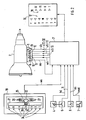
- Fig. 1, 1 shows an electrohydraulic control of an automatic motor vehicle transmission 2, as described, for example, in Bosch 'Technical Reports', 7 (1983) 4 on pages 160 to 166 and in ATZ 85 (1983) 6 on pages 401 to 405.
- a control unit 3 controls as a function of a kick-down signal kd of a kick-down sensor 4 on the accelerator pedal of the motor vehicle and an idle signal 11 of a throttle valve switch 5, an engine load signal ml of a load signal transmitter 6 (air quantity or air mass measuring device, throttle valve angle transmitter) and an engine speed signal nmot of an engine speed sensor 7 of an internal combustion engine (not shown) and a transmission output speed signal na of a transmission output signal sensor 8 a pressure regulator 9 for a hydraulic fluid (signal output ds), a first electromagnetic valve 10 for controlling a converter or a converter lock-up clutch (signal output wk), a second solenoid valve 11 for controlling the gear stage change between gear stages I and II (signal output sI / II), - A third solenoid valve 12 for controlling the gear stage change between gear stages II and III (signal output sII / III) and - A fourth solenoid valve 13 for controlling the gear change between gears III and IV (signal output SIII /
- the control can be influenced by the vehicle driver via a selector lever 14 for preselecting the gear stages P, R, N, D, 3, 2, 1 and a program selector switch 15 for selecting driving programs E, S, M.
- the drive stages are P (parking), R (reverse gear stage), N (idle gear stage), D (all four gear stages IV, III, II, I), 3 (limitation to the three lowest gears III, II, I) and 2 (limitation to gears II and I) and 1 (limitation to the first gear I).
- the preselected and selected gear can differ.
- conventional automatic transmissions only display a gear stage in accordance with the selector lever position, the information about the actual state of the gearbox (engaged gear stage, selected drive program) is lost.
- the transmission control 1 according to FIG. 1 is therefore extended by a display device 16 which comprises first display elements 17 and second display elements 18.
- the first display elements show the position of the selector lever, that is, the preselected speed level (P, R, N, D, 3, 2, 1), by the corresponding display element in the form of a triangle symbol identified by the respective alphanumeric characters is controlled.
- the second display elements 18 particularly (or even only) indicate an engaged gear stage IV, III, II or I in the semi-automatic operating mode.
- the first display elements 17 are of course not controlled in the semi-automatic mode with manual preselection of the gear stages.
- Arranging the first and second display elements in two parallel rows (or according to a shift pattern of the selector lever) results in a particularly memorable and easy to understand display of the transmission status.
- a particularly advantageous arrangement with a selector lever unit 19 is shown here, which is described in more detail in DE-OS 38 07 881.
- a selector lever 20 is guided in a first shift gate 21 and a second shift gate 22 parallel thereto.
- First shift gate 21 and second shift gate 22 are connected to one another via a transverse gate 23 arranged at the speed level D of the first shift gate.
- the (conventionally constructed) first shift gate 21 serves to preselect the driving stages P, R, N, D, 3, 2, 1 in the fully automatic operating mode.
- the fully automatic mode of operation can be exited from the driving stage D and the semi-automatic mode of operation can be selected by moving the shift lever 20 via the transverse alley 23 into the second shift alley 22.
- the semi-automatic mode of operation can be selected by moving the shift lever 20 via the transverse alley 23 into the second shift alley 22.
- an upshift or downshift by one gear stage can be preselected, which, if it falls within plausible speed ranges, from Control unit 3 'controlled, is executed.
- the changed gear is then displayed on the second display elements 18.
- the semi-automatic mode of operation can be exited again in favor of the fully automatic one.
- position detectors 24 for the positions P, R, N, D, 3, 2, 1 of the first shift gate 21 as well as a position detector 25 for detecting the shift lever position in the second shift gate 22 and a position detector 26 and 27 for sensing the Upshift and the downshift pre-selection position of the shift lever 20 are provided.
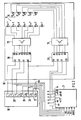
- a coding switch can also be arranged on the shift lever, which translates the seven angular positions of the selector lever 20 into a specific three-digit binary code. It is also conceivable to transmit the signals of the ten position detectors 24 to 27 via a coding module in a four-digit binary code in order to further reduce the number of lines (output signal ws) between the shift lever unit 19 and the modified control unit 3 '. There, the corresponding binary information is then converted back into the shift lever position (decoded) in a decoding unit or in a software sub-program.
- the control of the display device 16 can now either be carried out via the control unit 3 'by this detects the selector lever position and controls the first display elements 17 and the second display elements 18 in accordance with the selector lever position and the gear position selected.
- the three lines from the decoding switch 24 'of the selector lever unit 19 are fed together with the signal from the position detector 25 (shift lever 20 in the second shift gate 22) to a first decoding module 28 which, depending on which is applied to its inputs A0 - A3 Signal combination at one of its outputs D0 - D6 controls a signal to control one of the first display elements 17 via a driver module 29 (which may possibly be omitted).
- Light-emitting diodes are drawn in here as display elements without any restriction of generality.
- a second decoder module 30 is acted upon at its inputs AO - A3 with the signals of the signal outputs sI / II, sII / III, sIII / IV of the modified control device 3 'for actuating the switching valves 11, 12, 13 and with the signal of the position detector 25 and controls one of the outputs D0 - D4 depending on the input combination; a driver module 31 amplifies the output signal and controls one of the display elements 18, it being possible here to additionally use a display element marked with M which lights up continuously in the semi-automatic operating mode.
- the two decoder modules can also be designed as programmable memory modules, with a specific input data (or a specific signal combination) serving as an address driving a specific memory cell at the inputs AO-A3 (address bus); this contains a data with a logical one at the position of the outputs D0 - D6 (data bus) which controls the corresponding display element.
- the position detector 25 is used to control either the first or the second display elements 17, 18.
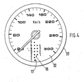
- FIG. 4 shows the arrangement of the display device with the first display elements 17 and the second display elements 18 within a display front panel 32 of a vehicle speed display instrument 33.
- the display device can of course be arranged in every display instrument of a motor vehicle, although this should be as central as possible in the driver's perspective.
- the controlled display elements should be visible under all conceivable lighting conditions (extraneous light, scattered light) at least as long as either the ignition switch of the motor vehicle is actuated or lighting (headlights, interior lighting) is switched on.
Landscapes
- Engineering & Computer Science (AREA)
- General Engineering & Computer Science (AREA)
- Mechanical Engineering (AREA)
- Arrangement And Mounting Of Devices That Control Transmission Of Motive Force (AREA)
- Control Of Transmission Device (AREA)
- Instrument Panels (AREA)
- Arrangement Or Mounting Of Control Devices For Change-Speed Gearing (AREA)
- Arrangements Of Lighting Devices For Vehicle Interiors, Mounting And Supporting Thereof, Circuits Therefore (AREA)
Applications Claiming Priority (2)
| Application Number | Priority Date | Filing Date | Title |
|---|---|---|---|
| DE3832971 | 1988-09-29 | ||
| DE3832971A DE3832971A1 (de) | 1988-09-29 | 1988-09-29 | Anzeigevorrichtung fuer ein automatisches kraftfahrzeuggetriebe |
Publications (3)
| Publication Number | Publication Date |
|---|---|
| EP0361011A2 true EP0361011A2 (fr) | 1990-04-04 |
| EP0361011A3 EP0361011A3 (fr) | 1991-06-12 |
| EP0361011B1 EP0361011B1 (fr) | 1994-04-13 |
Family
ID=6363912
Family Applications (1)
| Application Number | Title | Priority Date | Filing Date |
|---|---|---|---|
| EP89113533A Expired - Lifetime EP0361011B1 (fr) | 1988-09-29 | 1989-07-22 | Dispositif indicateur pour une transmission automatique de véhicule |
Country Status (6)
| Country | Link |
|---|---|
| US (1) | US5009128A (fr) |
| EP (1) | EP0361011B1 (fr) |
| JP (3) | JP2840860B2 (fr) |
| DE (2) | DE3832971A1 (fr) |
| ES (1) | ES2051329T3 (fr) |
| HK (1) | HK41597A (fr) |
Cited By (13)
| Publication number | Priority date | Publication date | Assignee | Title |
|---|---|---|---|---|
| GB2239682A (en) * | 1990-01-02 | 1991-07-10 | Automotive Prod Co Ltd | Gear ratio selection indicator |
| WO1992017719A1 (fr) * | 1991-04-03 | 1992-10-15 | The Torrington Company | Systeme numerique de detection de position d'une boite de vitesses automatique |
| US5178042A (en) * | 1989-11-09 | 1993-01-12 | Aisin Aw Co., Ltd. | Manual speed selector of automatic vehicle transmission |
| FR2692956A1 (fr) * | 1992-06-29 | 1993-12-31 | Peugeot | Dispositif de détection de la position et/ou du changement de position d'un levier de manÓoeuvre. |
| EP0718142A3 (fr) * | 1994-12-24 | 1996-08-07 | Massey Ferguson Sa | |
| EP0685664A3 (fr) * | 1994-06-01 | 1997-07-23 | Zahnradfabrik Friedrichshafen | Dispositif de commande de changement de rapport pour transmission automatique. |
| DE19609585A1 (de) * | 1996-03-12 | 1997-09-18 | Bayerische Motoren Werke Ag | Verfahren zum Steuern eines stufenlosen Getriebes sowie Vorrichtung hierzu |
| DE19714495A1 (de) * | 1997-04-08 | 1998-10-15 | Bayerische Motoren Werke Ag | Wähleinrichtung mit einer Anzeigeeinrichtung |
| EP0856687A3 (fr) * | 1997-01-31 | 2000-01-05 | Fujikiko Kabushiki Kaisha | Dispositif de commande manuelle d'une transmission automatique |
| DE19856508A1 (de) * | 1998-12-08 | 2000-06-15 | Zahnradfabrik Friedrichshafen | Schalteinrichtung an einem Getriebe |
| EP1052434A2 (fr) | 1999-05-11 | 2000-11-15 | Dr.Ing. h.c.F. Porsche Aktiengesellschaft | Indicateur de vitessse pour une transmission automatique de véhicule automobile |
| JP2011098598A (ja) * | 2009-11-04 | 2011-05-19 | Nemoto Kyorindo:Kk | 車両の自動変速装置のギア段数を明示できる車両用計器盤 |
| WO2021037402A1 (fr) * | 2019-08-27 | 2021-03-04 | Bayerische Motoren Werke Aktiengesellschaft | Système de boîte de vitesses doté d'une boîte de vitesses manuelle automatisée |
Families Citing this family (56)
| Publication number | Priority date | Publication date | Assignee | Title |
|---|---|---|---|---|
| JPH03153957A (ja) * | 1989-11-09 | 1991-07-01 | Aisin Aw Co Ltd | 車両用自動変速機の手動選択装置 |
| DE4005588C2 (de) * | 1990-02-22 | 1995-03-23 | Porsche Ag | Schaltvorrichtung für ein automatisches Getriebe |
| JP2748642B2 (ja) * | 1990-03-12 | 1998-05-13 | トヨタ自動車株式会社 | 自動変速機の制御装置 |
| US5245313A (en) * | 1991-02-20 | 1993-09-14 | Atoma International, Inc. | Automatic transmission lever position indicating device |
| EP0513424B1 (fr) * | 1991-05-17 | 1995-10-25 | Siemens Aktiengesellschaft | Transmission d'un automobile avec un dispositif de commande |
| GB2256683B (en) * | 1991-06-15 | 1994-05-25 | Gen Motors France | Transmission control module |
| DE69212446T2 (de) * | 1991-12-19 | 1996-11-28 | Mitsubishi Heavy Ind Ltd | Elektronisch, gesteuertes, automatisches Getriebe eines Fahrzeugs |
| DE69303415T2 (de) * | 1992-04-24 | 1997-01-09 | Aisin Aw Co | Schaltsteuerungssystem für von Hand schaltbares, automatisches Getriebe |
| US5325083A (en) * | 1992-05-01 | 1994-06-28 | Chrysler Corporation | Manual valve position sensing system |
| US5261298A (en) * | 1992-06-26 | 1993-11-16 | Eaton Corporation | Enhanced semi-automated mechanical transmission system |
| US5415056A (en) * | 1992-09-21 | 1995-05-16 | Toyota Jidosha Kabushiki Kaisha | Shift control system for manually shiftable automatic transmission |
| US5420565A (en) * | 1993-05-26 | 1995-05-30 | Chrysler Corporation | Electronic PRNODDL display system |
| US5437204A (en) * | 1993-12-20 | 1995-08-01 | Ford Motor Company | System for selecting the operating ranges of an automatic transmission |
| US5433124A (en) * | 1993-12-20 | 1995-07-18 | Ford Motor Company | Electronic range selection in an automatic transmission |
| US5722292A (en) * | 1994-06-02 | 1998-03-03 | Chrysler Corporation | Shift control mechanism to manually shift an automatic transmission |
| US5509322A (en) * | 1994-06-02 | 1996-04-23 | Chrysler Corporation | Shift control mechanism to manually shift an automatic transmission |
| US5492509A (en) * | 1994-06-06 | 1996-02-20 | Ford Motor Company | Operating range selection of an automatic transmission |
| US5492523A (en) * | 1994-06-06 | 1996-02-20 | Ford Motor Company | Operating range selection of an automatic transmission |
| US5762580A (en) * | 1994-06-06 | 1998-06-09 | Ford Global Technologies, Inc. | Operating range selection of an automatic transmission |
| GB9415965D0 (en) * | 1994-08-06 | 1994-09-28 | Eaton Corp | Continuous selection control for semi-automatic mechanical transmission |
| ES2102967B1 (es) * | 1995-04-26 | 1998-04-01 | Fico Triad Sa | Dispositivo de señalizacion de la posicion del brazo de palanca de cambios de velocidades automaticos. |
| US5767769A (en) * | 1995-07-28 | 1998-06-16 | Chrysler Corporation | Method of displaying a shift lever position for an electronically-controlled automatic transmission |
| US5680307A (en) * | 1995-06-28 | 1997-10-21 | Chrysler Corporation | Method of shifting in a manual mode of an electronically-controlled automatic transmission system |
| US5675315A (en) * | 1995-07-28 | 1997-10-07 | Chrysler Corporation | Electronic gear display for an electronically-controlled automatic transmission system |
| GB9525055D0 (en) * | 1995-12-07 | 1996-02-07 | Eaton Corp | Controled for automated mechanical transmission system |
| US5791197A (en) * | 1996-07-24 | 1998-08-11 | Grand Haven Stamped Products | Automatic transmission shifter with manual shift mode |
| JP3216542B2 (ja) * | 1996-09-02 | 2001-10-09 | トヨタ自動車株式会社 | 自動変速機の変速レンジ制御装置 |
| JP3600382B2 (ja) * | 1996-09-19 | 2004-12-15 | ジヤトコ株式会社 | 自動変速機の変速制御装置 |
| DE19823598B4 (de) * | 1997-06-13 | 2007-11-15 | Luk Gs Verwaltungs Kg | Verfahren und Vorrichtung zum Anzeigen der Neutralstellung eines im Antriebsstrang eines Kraftfahrzeugs enthaltenen Schaltgetriebes |
| JP3185720B2 (ja) * | 1997-07-29 | 2001-07-11 | 日産自動車株式会社 | マニュアルシフト機能付き自動変速機の制御回路 |
| EP0895003B1 (fr) * | 1997-07-29 | 2004-10-06 | Nissan Motor Company Limited | Sélecteur de vitesse de transmission automatique |
| JPH11115525A (ja) * | 1997-10-21 | 1999-04-27 | Tokai Rika Co Ltd | シフトレバー装置 |
| DE19747269A1 (de) * | 1997-10-25 | 1999-04-29 | Bayerische Motoren Werke Ag | Kraftfahrzeug |
| US6018294A (en) * | 1998-05-18 | 2000-01-25 | Chrysler Corporation | Automatic transmission shift indicator system |
| DE19844276C2 (de) * | 1998-09-26 | 2000-11-09 | Porsche Ag | Wähleinrichtung für ein Fahrzeug-Getriebe sowie Schaltermodul hierzu |
| US6072390A (en) * | 1999-03-31 | 2000-06-06 | Daimlerchrysler Corporation | Position sensing system for manually operated shift lever of a vehicle transmission |
| KR100325225B1 (ko) * | 1999-06-23 | 2002-03-04 | 이계안 | 차량용 자동 변속기의 변속단 표시장치 |
| DE19946560A1 (de) * | 1999-09-29 | 2003-02-13 | Zahnradfabrik Friedrichshafen | Vorankündigung einer automatisch ausgeführten Schaltung |
| NO312564B1 (no) * | 2000-01-25 | 2002-05-27 | Kongsberg Automotive Asa | Girskifteanordning for kjöretöyer |
| DE10048577B4 (de) * | 2000-09-30 | 2010-11-25 | Volkswagen Ag | Schalteinrichtung zur Steuerung eines Automatik-Getriebes und Verfahren zur Steuerung der visuellen Anzeigen der Schalteinrichtung |
| JP2002147605A (ja) * | 2000-11-16 | 2002-05-22 | Aisin Aw Co Ltd | レンジ切替表示装置及びレンジ切替表示方法 |
| JP3792586B2 (ja) * | 2002-03-12 | 2006-07-05 | 本田技研工業株式会社 | 車両の変速操作装置 |
| DE10211968B4 (de) * | 2002-03-19 | 2004-02-05 | Preh-Werke Gmbh & Co. Kg | Anzeigeeinheit für eine Wählhebelschaltung |
| DE10239912B4 (de) * | 2002-08-30 | 2007-09-20 | Audi Ag | Steuervorrichtung und Verfahren zur Steuerung für ein automatisch und manuell schaltbares Wechselgetriebe |
| US7049600B2 (en) * | 2002-09-18 | 2006-05-23 | The Board Of Trustees Of The Leland Stanford Junior University | Scintillation crystal detection arrays for radiation imaging devices |
| JP4049028B2 (ja) * | 2003-06-18 | 2008-02-20 | トヨタ自動車株式会社 | 変速機のシフト操作装置 |
| EP1491799A1 (fr) | 2003-06-24 | 2004-12-29 | Ford Global Technologies, LLC, A subsidary of Ford Motor Company | Dispositif d'affichage |
| DE112005002398T5 (de) * | 2004-09-30 | 2007-08-16 | Stanford University, Palo Alto | Hochauflösender Halbleiterkristall-Bildgeber |
| JP2006273111A (ja) * | 2005-03-29 | 2006-10-12 | Mazda Motor Corp | 自動変速機付き車両の表示装置 |
| JP4721046B2 (ja) * | 2005-07-12 | 2011-07-13 | 横河電機株式会社 | ロータリスイッチ設定表示装置 |
| US20090091313A1 (en) * | 2007-10-04 | 2009-04-09 | Teeters Dale E | Inductive position sensor with integrated led indicators |
| JP4593654B2 (ja) | 2008-06-10 | 2010-12-08 | ジヤトコ株式会社 | 有段自動変速機 |
| US8289718B2 (en) * | 2010-10-29 | 2012-10-16 | Zf Friedrichshafen Ag | Connector assembly for electrical and mechanical interconnection of modules |
| KR102599389B1 (ko) | 2018-06-29 | 2023-11-09 | 현대자동차주식회사 | 전자식 변속시스템의 변속신호 송출방법 |
| US11073205B2 (en) * | 2019-03-29 | 2021-07-27 | Dus Operating Inc. | Shift lever assembly with position sensing |
| FR3117588B1 (fr) * | 2020-12-14 | 2022-11-11 | Safran | Procede de surveillance d’une usure d’un actionneur |
Family Cites Families (21)
| Publication number | Priority date | Publication date | Assignee | Title |
|---|---|---|---|---|
| DE891661C (de) * | 1951-12-14 | 1953-10-01 | Daimler Benz Ag | Geschwindigkeitsanzeigevorrichtung fuer Kraftfahrzeuge |
| US3650161A (en) * | 1969-10-18 | 1972-03-21 | Toyota Motor Co Ltd | Automatic shift control system for automatic transmission |
| US3646835A (en) * | 1969-10-18 | 1972-03-07 | Toyota Motor Co Ltd | Shift control system for vehicle automatic transmission |
| GB1439675A (en) * | 1973-05-29 | 1976-06-16 | Ferranti Ltd | Electrical systems for automatically controlling the gear changes of road vehicles |
| DE2507086A1 (de) * | 1975-02-19 | 1976-08-26 | Daimler Benz Ag | Ganganzeige fuer kraftfahrzeuge |
| US4425620A (en) * | 1981-01-28 | 1984-01-10 | Steiger Tractor, Inc. | Electrical control for power shift transmission |
| JPS6145541Y2 (fr) * | 1981-05-20 | 1986-12-22 | ||
| DE3237517A1 (de) * | 1982-10-09 | 1984-04-12 | Wabco Westinghouse Fahrzeugbremsen GmbH, 3000 Hannover | Schaltanzeige fuer eine gangschaltung |
| DE3237508A1 (de) * | 1982-10-09 | 1984-04-19 | Wabco Westinghouse Fahrzeugbremsen GmbH, 3000 Hannover | Gangschaltung fuer ein fremdkraftbetaetigtes getriebe |
| DE3337930C2 (de) * | 1982-12-23 | 1986-02-13 | Zahnradfabrik Friedrichshafen Ag, 7990 Friedrichshafen | Wählschalter in einer Schaltsteuerung für Automatgetriebe |
| JPS60252853A (ja) * | 1984-05-30 | 1985-12-13 | Mitsubishi Motors Corp | 自動変速装置 |
| EP0269772B1 (fr) * | 1986-12-05 | 1990-03-21 | Eaton Corporation | Commande de transmission mécanique semi-automatique et procédé de commande |
| DE3429531A1 (de) * | 1984-08-10 | 1986-02-20 | Wabco Westinghouse Fahrzeugbremsen GmbH, 3000 Hannover | Hilfskraftbetaetigtes fahrzeuggetriebe |
| US4610179A (en) * | 1984-09-07 | 1986-09-09 | Peter D. Adams | Manual shift control lever device and self-contained electronic control for transmissions |
| JPS61157855A (ja) * | 1984-12-27 | 1986-07-17 | Nissan Motor Co Ltd | 自動変速機の手動変速装置 |
| DE3608208A1 (de) * | 1985-03-23 | 1986-09-25 | Zahnradfabrik Friedrichshafen Ag, 7990 Friedrichshafen | Steuereinrichtung zum schalten von stufenwechselgetrieben |
| JPS62161023U (fr) * | 1986-02-14 | 1987-10-13 | ||
| DE3717675C5 (de) * | 1987-05-26 | 2005-12-15 | Bayerische Motoren Werke Ag | Schalteinrichtung für ein Kraftfahrzeug mit automatischem Getriebe |
| DE3717674A1 (de) * | 1987-05-26 | 1988-12-08 | Bayerische Motoren Werke Ag | Schaltsteuereinrichtung eines kraftfahrzeugs mit automatischem getriebe |
| DE3807881A1 (de) * | 1988-03-10 | 1989-09-21 | Porsche Ag | Schaltvorrichtung fuer ein automatikgetriebe eines kraftfahrzeugs |
| US4873891A (en) * | 1988-12-19 | 1989-10-17 | Gary Guanciale | Apparatus for improving efficiency and consistency of a drag race car |
-
1988
- 1988-09-29 DE DE3832971A patent/DE3832971A1/de active Granted
-
1989
- 1989-07-22 ES ES89113533T patent/ES2051329T3/es not_active Expired - Lifetime
- 1989-07-22 EP EP89113533A patent/EP0361011B1/fr not_active Expired - Lifetime
- 1989-07-22 DE DE58907448T patent/DE58907448D1/de not_active Expired - Lifetime
- 1989-09-28 US US07/413,757 patent/US5009128A/en not_active Expired - Lifetime
- 1989-09-29 JP JP1252462A patent/JP2840860B2/ja not_active Expired - Lifetime
-
1997
- 1997-01-30 JP JP01669897A patent/JP3358076B2/ja not_active Expired - Lifetime
- 1997-04-03 HK HK41597A patent/HK41597A/xx not_active IP Right Cessation
-
1999
- 1999-02-24 JP JP04705899A patent/JP3442682B2/ja not_active Expired - Lifetime
Cited By (22)
| Publication number | Priority date | Publication date | Assignee | Title |
|---|---|---|---|---|
| US5178042A (en) * | 1989-11-09 | 1993-01-12 | Aisin Aw Co., Ltd. | Manual speed selector of automatic vehicle transmission |
| GB2239682A (en) * | 1990-01-02 | 1991-07-10 | Automotive Prod Co Ltd | Gear ratio selection indicator |
| WO1992017719A1 (fr) * | 1991-04-03 | 1992-10-15 | The Torrington Company | Systeme numerique de detection de position d'une boite de vitesses automatique |
| AU659151B2 (en) * | 1991-04-03 | 1995-05-11 | Torrington Company, The | Digital position system for automatic transmissions |
| DE4290856C2 (de) * | 1991-04-03 | 2002-11-21 | Snr Roulements Annecy | Digitales Positions-Sensorsystem für automatische Getriebe |
| FR2692956A1 (fr) * | 1992-06-29 | 1993-12-31 | Peugeot | Dispositif de détection de la position et/ou du changement de position d'un levier de manÓoeuvre. |
| EP0685664A3 (fr) * | 1994-06-01 | 1997-07-23 | Zahnradfabrik Friedrichshafen | Dispositif de commande de changement de rapport pour transmission automatique. |
| EP0718142A3 (fr) * | 1994-12-24 | 1996-08-07 | Massey Ferguson Sa | |
| DE19609585A1 (de) * | 1996-03-12 | 1997-09-18 | Bayerische Motoren Werke Ag | Verfahren zum Steuern eines stufenlosen Getriebes sowie Vorrichtung hierzu |
| US6044790A (en) * | 1997-01-31 | 2000-04-04 | Fujikiko Kabushiki Kaisha | Manual operating apparatus for an automatic transmission |
| EP0856687A3 (fr) * | 1997-01-31 | 2000-01-05 | Fujikiko Kabushiki Kaisha | Dispositif de commande manuelle d'une transmission automatique |
| US6046673A (en) * | 1997-04-08 | 2000-04-04 | Bayerische Motoren Werke Aktiengesellschaft | Selecting arrangement having a display device |
| EP0870955A3 (fr) * | 1997-04-08 | 2000-05-17 | Bayerische Motoren Werke Aktiengesellschaft, Patentabteilung AJ-3 | Levier de changement de vitesse avec un dispositif de signalisation de position |
| DE19714495A1 (de) * | 1997-04-08 | 1998-10-15 | Bayerische Motoren Werke Ag | Wähleinrichtung mit einer Anzeigeeinrichtung |
| DE19856508A1 (de) * | 1998-12-08 | 2000-06-15 | Zahnradfabrik Friedrichshafen | Schalteinrichtung an einem Getriebe |
| EP1052434A2 (fr) | 1999-05-11 | 2000-11-15 | Dr.Ing. h.c.F. Porsche Aktiengesellschaft | Indicateur de vitessse pour une transmission automatique de véhicule automobile |
| US6341883B1 (en) | 1999-05-11 | 2002-01-29 | Dr. Ing. H.C.F. Porsche Aktiengesellschaft | Display device for an automatic motor vehicle transmission and method of using same |
| EP1052434A3 (fr) * | 1999-05-11 | 2002-08-14 | Dr.Ing. h.c.F. Porsche Aktiengesellschaft | Indicateur de vitessse pour une transmission automatique de véhicule automobile |
| JP2011098598A (ja) * | 2009-11-04 | 2011-05-19 | Nemoto Kyorindo:Kk | 車両の自動変速装置のギア段数を明示できる車両用計器盤 |
| WO2021037402A1 (fr) * | 2019-08-27 | 2021-03-04 | Bayerische Motoren Werke Aktiengesellschaft | Système de boîte de vitesses doté d'une boîte de vitesses manuelle automatisée |
| CN114072600A (zh) * | 2019-08-27 | 2022-02-18 | 宝马股份公司 | 具有自动变速器的传动系统 |
| US11867284B2 (en) | 2019-08-27 | 2024-01-09 | Bayerische Motoren Werke Aktiengesellschaft | Gearbox system with an automated manual gearbox |
Also Published As
| Publication number | Publication date |
|---|---|
| JPH02133240A (ja) | 1990-05-22 |
| US5009128A (en) | 1991-04-23 |
| JPH11321369A (ja) | 1999-11-24 |
| EP0361011B1 (fr) | 1994-04-13 |
| EP0361011A3 (fr) | 1991-06-12 |
| DE3832971C2 (fr) | 1993-03-25 |
| ES2051329T3 (es) | 1994-06-16 |
| DE58907448D1 (de) | 1994-05-19 |
| JPH1044816A (ja) | 1998-02-17 |
| JP3358076B2 (ja) | 2002-12-16 |
| DE3832971A1 (de) | 1990-04-12 |
| JP2840860B2 (ja) | 1998-12-24 |
| JP3442682B2 (ja) | 2003-09-02 |
| HK41597A (en) | 1997-04-11 |
Similar Documents
| Publication | Publication Date | Title |
|---|---|---|
| EP0361011B1 (fr) | Dispositif indicateur pour une transmission automatique de véhicule | |
| DE3832970C2 (de) | Anzeigevorrichtung für ein automatisches Kraftfahrzeuggetriebe | |
| DE4005588C2 (de) | Schaltvorrichtung für ein automatisches Getriebe | |
| EP1039178B1 (fr) | Dispositif et méthode pour commander des changements de vitesse dans une transmission automatique | |
| DE4311886C2 (de) | Vorrichtung und Verfahren zum Steuern eines selbsttätig schaltenden Getriebes | |
| DE3139838C2 (de) | Steuervorrichtung für ein Automatikgetriebe in einem Kraftfahrzeug | |
| EP0416227B1 (fr) | Transmission pour véhicule automobile | |
| DE3237508A1 (de) | Gangschaltung fuer ein fremdkraftbetaetigtes getriebe | |
| EP1338831A2 (fr) | Dispositif de changement de vitesse pour transmission | |
| DE10052881C2 (de) | Steuervorrichtung für ein Getriebe eines Kraftfahrzeuges | |
| DE10157393B4 (de) | Verfahren und Vorrichtung zur Steuerung der Schaltungen eines automatischen Getriebes eines Kraftfahrzeuges | |
| DE69302797T2 (de) | Steuervorrichtung für ein automatisiertes Getriebe eines Nutzfahrzeuges | |
| DE69402101T2 (de) | Gangschaltungseinrichtung für ein automatisches Kraftfahrzeuggetriebe | |
| DE102007037750B4 (de) | Wählhebel für ein Kraftfahrzeug | |
| DE10048577B4 (de) | Schalteinrichtung zur Steuerung eines Automatik-Getriebes und Verfahren zur Steuerung der visuellen Anzeigen der Schalteinrichtung | |
| DE3939030A1 (de) | Schaltstellungsanzeige fuer schalt- oder waehlhebel | |
| DE19957866B4 (de) | Verfahren und Vorrichtung zur Steuerung der Schaltbewegungen eines Schalt-Wählhebels für das automatische Schaltgetriebe eines Kraftfahrzeuges | |
| EP1081414B1 (fr) | Dispositif de changement de vitesses pour commander une transmission automatique de véhicule automobile | |
| DE102004026106B4 (de) | Schaltvorrichtung eines Automatikgetriebes für Fahrzeuge | |
| DE19732369B4 (de) | Verfahren zur Ansteuerung eines Automatikgetriebes und eine Schaltvorrichtung zur Auswahl der Fahrstrategien | |
| DE4219382B4 (de) | Fahrstilangepaßte Gangwechselsteuerung bei elektronisch gesteuerten Automatikgetrieben in Kraftfahrzeugen | |
| EP0713986B1 (fr) | Dispositif et méthode de commande d'une transmission à variation continue | |
| DE19707141A1 (de) | Anordnung zum Erfassen von Betätigungs- oder Schaltzuständen einer Getriebebetätigungsvorrichtung | |
| DE3513778A1 (de) | Steuereinrichtung fuer ein selbsttaetig schaltendes geschwindigkeitswechselgetriebe | |
| DE10356380B4 (de) | Verfahren zur Steuerung eines Gangwechsels |
Legal Events
| Date | Code | Title | Description |
|---|---|---|---|
| PUAI | Public reference made under article 153(3) epc to a published international application that has entered the european phase |
Free format text: ORIGINAL CODE: 0009012 |
|
| AK | Designated contracting states |
Kind code of ref document: A2 Designated state(s): DE ES FR GB IT SE |
|
| PUAL | Search report despatched |
Free format text: ORIGINAL CODE: 0009013 |
|
| AK | Designated contracting states |
Kind code of ref document: A3 Designated state(s): DE ES FR GB IT SE |
|
| 17P | Request for examination filed |
Effective date: 19911008 |
|
| 17Q | First examination report despatched |
Effective date: 19921023 |
|
| ITF | It: translation for a ep patent filed | ||
| GRAA | (expected) grant |
Free format text: ORIGINAL CODE: 0009210 |
|
| AK | Designated contracting states |
Kind code of ref document: B1 Designated state(s): DE ES FR GB IT SE |
|
| REF | Corresponds to: |
Ref document number: 58907448 Country of ref document: DE Date of ref document: 19940519 |
|
| GBT | Gb: translation of ep patent filed (gb section 77(6)(a)/1977) |
Effective date: 19940503 |
|
| REG | Reference to a national code |
Ref country code: ES Ref legal event code: FG2A Ref document number: 2051329 Country of ref document: ES Kind code of ref document: T3 |
|
| ET | Fr: translation filed | ||
| EAL | Se: european patent in force in sweden |
Ref document number: 89113533.7 |
|
| PLBE | No opposition filed within time limit |
Free format text: ORIGINAL CODE: 0009261 |
|
| STAA | Information on the status of an ep patent application or granted ep patent |
Free format text: STATUS: NO OPPOSITION FILED WITHIN TIME LIMIT |
|
| 26N | No opposition filed | ||
| REG | Reference to a national code |
Ref country code: GB Ref legal event code: IF02 |
|
| PGFP | Annual fee paid to national office [announced via postgrant information from national office to epo] |
Ref country code: ES Payment date: 20080729 Year of fee payment: 20 Ref country code: DE Payment date: 20080623 Year of fee payment: 20 |
|
| PGFP | Annual fee paid to national office [announced via postgrant information from national office to epo] |
Ref country code: IT Payment date: 20080725 Year of fee payment: 20 Ref country code: FR Payment date: 20080715 Year of fee payment: 20 |
|
| PGFP | Annual fee paid to national office [announced via postgrant information from national office to epo] |
Ref country code: GB Payment date: 20080722 Year of fee payment: 20 |
|
| PGFP | Annual fee paid to national office [announced via postgrant information from national office to epo] |
Ref country code: SE Payment date: 20080714 Year of fee payment: 20 |
|
| REG | Reference to a national code |
Ref country code: ES Ref legal event code: PC2A |
|
| REG | Reference to a national code |
Ref country code: FR Ref legal event code: TP |
|
| REG | Reference to a national code |
Ref country code: GB Ref legal event code: PE20 Expiry date: 20090721 |
|
| EUG | Se: european patent has lapsed | ||
| REG | Reference to a national code |
Ref country code: ES Ref legal event code: FD2A Effective date: 20090723 |
|
| PG25 | Lapsed in a contracting state [announced via postgrant information from national office to epo] |
Ref country code: ES Free format text: LAPSE BECAUSE OF EXPIRATION OF PROTECTION Effective date: 20090723 |
|
| REG | Reference to a national code |
Ref country code: FR Ref legal event code: CD |
|
| PG25 | Lapsed in a contracting state [announced via postgrant information from national office to epo] |
Ref country code: GB Free format text: LAPSE BECAUSE OF EXPIRATION OF PROTECTION Effective date: 20090721 |