EP0361032B1 - Propellant charge igniter with a cutting charge ignited by the propellant charge powder - Google Patents
Propellant charge igniter with a cutting charge ignited by the propellant charge powder Download PDFInfo
- Publication number
- EP0361032B1 EP0361032B1 EP89114499A EP89114499A EP0361032B1 EP 0361032 B1 EP0361032 B1 EP 0361032B1 EP 89114499 A EP89114499 A EP 89114499A EP 89114499 A EP89114499 A EP 89114499A EP 0361032 B1 EP0361032 B1 EP 0361032B1
- Authority
- EP
- European Patent Office
- Prior art keywords
- charge
- flame
- base piece
- igniter according
- casing
- Prior art date
- Legal status (The legal status is an assumption and is not a legal conclusion. Google has not performed a legal analysis and makes no representation as to the accuracy of the status listed.)
- Expired - Lifetime
Links
- 239000003380 propellant Substances 0.000 title abstract description 23
- 239000000843 powder Substances 0.000 title description 3
- 238000000926 separation method Methods 0.000 claims abstract description 23
- 239000007789 gas Substances 0.000 claims abstract description 17
- 238000007789 sealing Methods 0.000 claims abstract description 6
- 238000002485 combustion reaction Methods 0.000 claims description 2
- 239000002184 metal Substances 0.000 claims 5
- 241000826860 Trapezium Species 0.000 claims 4
- 229920003023 plastic Polymers 0.000 claims 1
- 239000004033 plastic Substances 0.000 claims 1
- 230000037452 priming Effects 0.000 abstract 1
- 238000010304 firing Methods 0.000 description 3
- 238000011161 development Methods 0.000 description 2
- 230000018109 developmental process Effects 0.000 description 2
- 229910017518 Cu Zn Inorganic materials 0.000 description 1
- 239000000567 combustion gas Substances 0.000 description 1
- 230000001419 dependent effect Effects 0.000 description 1
- 230000002349 favourable effect Effects 0.000 description 1
- 230000035515 penetration Effects 0.000 description 1
- 230000000750 progressive effect Effects 0.000 description 1
- 230000007704 transition Effects 0.000 description 1
Images

Classifications
-
- F—MECHANICAL ENGINEERING; LIGHTING; HEATING; WEAPONS; BLASTING
- F42—AMMUNITION; BLASTING
- F42C—AMMUNITION FUZES; ARMING OR SAFETY MEANS THEREFOR
- F42C19/00—Details of fuzes
- F42C19/08—Primers; Detonators
- F42C19/0823—Primers or igniters for the initiation or the propellant charge in a cartridged ammunition
- F42C19/0826—Primers or igniters for the initiation or the propellant charge in a cartridged ammunition comprising an elongated perforated tube, i.e. flame tube, for the transmission of the initial energy to the propellant charge, e.g. used for artillery shells and kinetic energy penetrators
-
- F—MECHANICAL ENGINEERING; LIGHTING; HEATING; WEAPONS; BLASTING
- F42—AMMUNITION; BLASTING
- F42C—AMMUNITION FUZES; ARMING OR SAFETY MEANS THEREFOR
- F42C19/00—Details of fuzes
- F42C19/08—Primers; Detonators
- F42C19/0823—Primers or igniters for the initiation or the propellant charge in a cartridged ammunition
- F42C19/083—Primers or igniters for the initiation or the propellant charge in a cartridged ammunition characterised by the shape and configuration of the base element embedded in the cartridge bottom, e.g. the housing for the squib or percussion cap
Definitions
- the invention relates to a propellant lighter containing a base piece and an igniter head part with an igniter charge, a flame guide tube connected to the igniter charge with a flame guide tube head to a transfer charge surrounded by a combustible tube with blowout holes, and a cavity containing a separating set between the flame guide tube and a metallic sleeve running under the combustible tube, the cavity extending somewhat beyond the upper edge of the metallic sleeve and the base piece, and the combustible tube being separated off by gases from the separating set directly above the upper edge of the base piece.
- a partially combustible propellant lighter is known from DE 3 502 166 C2.
- the separating set is intended to completely separate a combustible tube which envelops the transfer charge from the base piece.
- the separation set is ignited by one or more bores in the head of the flame guide tube from back-flowing combustion gases from the tablet column of the transfer charge. Valve disks are present in the flame guide tube head, which fold over when the pressure rises due to the burning off of the separation set. With progressive combustion of the separation set, the pressure in the cavity rises so much that the desired separation of the combustible tube finally occurs immediately above the upper edge of the base piece.
- Burning off the transfer charge depends on the temperature. As a result, in particular at temperatures below 0 ° C., the separating charge can be ignited too early by back-flowing gas from the transfer charge, which occurs when the charge is sharp Shot causes disturbances in ballistics; there may also be a flare in the area where the cannon is locked.
- the object of the invention is a precise, adapted to the ambient temperature lighting of the separation set.
- a propellant lighter which is characterized by one or more connection holes between the cavity containing the separation set and the outside of the propellant charge lighter and a valve-like seal on the flame guide tube head to the sleeve, which on the one hand the direct entry of gases of the transfer charge into prevents the cavity, which, however, allows the gases of the separation set to escape through the combustible tube above the top channel of the base piece.
- the separating charge is therefore no longer ignited directly by the back-flowing gases of the tablet column of the transfer charge, since the rate of development of the propellant gas is temperature-dependent. Only when a certain propellant pressure has built up, i.e. If the burn-off only takes place regardless of the ambient temperature according to the specific properties of the propellant charge, the detachment charge is ignited from the outside through the casing via the firing holes. While the separation set was previously ignited 2 to 4 ms after the primary ignition element had been ignited and the start of pressure build-up due to the propellant charge gases started considerably later depending on the ambient temperature, it is now impossible to ignite the separation set too early. It is in a fixed time relationship with the pressure increase or the maximum pressure of the propellant gases.
- the seal on the flame guide tube head has the opposite function to that of the partially combustible propellant lighter known from DE 3 502 166 C2.
- the groove when viewed in cross section, has the shape of a trapezoid with the parallel sides parallel to the sleeve.
- a round cord ring rests on the rear surface of the sides of the trapezoid facing the base piece. It is important that the metallic sleeve supports the round cord ring from the outside in this "sealing position". Penetration of swaths of the transfer charge into the cavity with the separating charge is thus excluded.
- the seal on the flame guide tube head should be removed.
- the round cord ring is pushed so high in the groove by the gases of the separation charge that the gases can cut off the already weakened combustible tube above the base piece without leaving any residue. For this reason, it is favorable if the side of the trapezoid facing the transfer charge is chamfered or rounded. So there is always perfect barrel clearance after the shot.
- An electrically ignitable primary ignition element 15, which ignites an ignition charge 2, is installed in the base piece 1 of a propellant charge lighter.
- the pilot flame that forms is guided through a channel 3 in a flame guide tube 6 into the transfer charge 4 made up of tablets.
- the transfer charge 4 is held together by a combustible tube 5.
- the combustible tube 5 is partially drawn into the bottom piece 1, with it from the inside in the lower region is supported by a metallic sleeve 9, for example made of Cu Zn 37 F 37.
- a cavity 8 remains between the flame guide tube 6 and the combustible tube 5 or the sleeve 9, which cavity is largely filled with annular propellant tablets of the separation set 7. This cavity 8 is sealed off from the transfer charge 4, as described in FIG. 2.
- the base piece 1, the sleeve 9 and the head part 16 of the ignition piece are connected to one another by clamping sleeves 14.
- the firing bores 13 are characteristic, through which the separation set 7 is ignited from the outside by the propellant powder 19 surrounding the propellant charge lighter.
- the cavity 8 is connected here on the side facing the base piece 1 via a further cavity 10 to the four firing holes 13, which are evenly distributed over the circumference here.
- the ignition of the separating charge 7 is always time-coupled with a certain propellant gas pressure, and the combustible tube is cut off with great precision.
- the groove 18 here has approximately a trapezoidal cross-section, the transition upwards towards the transfer charge being rounded and conical, after at the bottom towards the bottom piece 1, the groove 18 abuts the sleeve 9 vertically.
- the round cord ring 12 should be deformed by about 3-20% when installed.
- the metallic sleeve 9 should extend so far that it can support the sealing ring 12 to the outside.
- the gap 20 between the metallic sleeve 9 and the flame guide tube head 11 is 0.75 mm.
- the area 21 between the upper edge of the base piece 1 and the outlet 22 of the groove 18 has a width between 0.8 mm and 2.5 mm, preferably between 1.3 mm and 2.0 mm.
- the outlet angle 24 of the side of the trapezoid facing away from the base piece 1 is 45 ° and the radius of curvature of the rounding 25 is 3 mm.
Landscapes
- Engineering & Computer Science (AREA)
- General Engineering & Computer Science (AREA)
- Lighters Containing Fuel (AREA)
- Portable Nailing Machines And Staplers (AREA)
- Fire-Extinguishing By Fire Departments, And Fire-Extinguishing Equipment And Control Thereof (AREA)
- Eye Examination Apparatus (AREA)
- Vending Machines For Individual Products (AREA)
- Seal Device For Vehicle (AREA)
- Air Bags (AREA)
Abstract
Description
Die Erfindung richtet sich auf einen Treibladunganzünder, enthaltend ein Bodenstück und ein Anzündstückkopfteil mit einer Anzündladung, ein sich an die Anzündladung anschließendes Flammleitrohr mit einem Flammleitrohrkopf zu einer von einem verbrennbaren Rohr mit Ausblaslöchern umgebenen Übertragungsladung, sowie einen einen Abtrennsatz enthaltenden Hohlraum zwischen dem Flammleitrohr und einer unter dem verbrennbaren Rohr verlaufenden metallischen Hülse, wobei der Hohlraum etwas über die Oberkante der metallischen Hülse und des Bodenstückes hinausreicht, und ein Abtrennen des verbrennbaren Rohres durch Gase des Abtrennsatzes unmittelbar über der Oberkante des Bodenstückes erfolgt.The invention relates to a propellant lighter containing a base piece and an igniter head part with an igniter charge, a flame guide tube connected to the igniter charge with a flame guide tube head to a transfer charge surrounded by a combustible tube with blowout holes, and a cavity containing a separating set between the flame guide tube and a metallic sleeve running under the combustible tube, the cavity extending somewhat beyond the upper edge of the metallic sleeve and the base piece, and the combustible tube being separated off by gases from the separating set directly above the upper edge of the base piece.
Ein teilverbrennbarer Treibladungsanzünder ist aus der DE 3 502 166 C2 bekannt. Durch den Abtrennsatz soll ein verbrennbares Rohr, das die Übertragungsladung umhüllt, vom Bodenstück vollständig abgetrennt werden. Der Abtrennsatz wird über eine oder mehrere Bohrungen im Kopf des Flammleitrohres von rückströmenden Verbrennungsgasen der Tablettensäule der Übertragungsladung angezündet. In dem Flammleitrohrkopf sind Ventilscheiben vorhanden, die umklappen, wenn der Druck durch Abbrennen des Abtrennsatzes ansteigt. Bei fortschreitender Verbrennung des Abtrennsatzes steigt der Druck in dem Hohlraum so stark an, daß es schließlich zu dem gewünschten Abtrennen des verbrennbaren Rohres unmittelbar über der Oberkante des Bodenstückes kommt.A partially combustible propellant lighter is known from DE 3 502 166 C2. The separating set is intended to completely separate a combustible tube which envelops the transfer charge from the base piece. The separation set is ignited by one or more bores in the head of the flame guide tube from back-flowing combustion gases from the tablet column of the transfer charge. Valve disks are present in the flame guide tube head, which fold over when the pressure rises due to the burning off of the separation set. With progressive combustion of the separation set, the pressure in the cavity rises so much that the desired separation of the combustible tube finally occurs immediately above the upper edge of the base piece.
Das Abbrennen der Übertragungsladung ist temperaturabhängig. Dadurch kann es insbesondere bei Temperaturen unter 0°C dazu kommen, daß das Anzünden der Abtrennladung durch rückströmendes Gas der Übertragungsladung zu früh erfolgt, was beim scharfen Schuß Störungen der Ballistik zur Folge hat; es kann auch zu einem Nachflammen im Verschlußbereich der Kanone kommen.Burning off the transfer charge depends on the temperature. As a result, in particular at temperatures below 0 ° C., the separating charge can be ignited too early by back-flowing gas from the transfer charge, which occurs when the charge is sharp Shot causes disturbances in ballistics; there may also be a flare in the area where the cannon is locked.
Aufgabe der Erfindung ist ein präzises, an die Umgebungstemperatur angepaßtes Anzünden des Abtrennsatzes.The object of the invention is a precise, adapted to the ambient temperature lighting of the separation set.
Die Aufgabe wird von einem Treibladungsanzünder gelöst, der gekennzeichnet ist durch eine oder mehrere eine Verbindung zwischen dem den Abtrennsatz enthaltenden Hohlraum und der Außenseite des Treibladungsanzünders herstellende Anfeuerungsbohrungen und eine ventilartig wirkende Abdichtung am Flammleitrohrkopf zur Hülse, die einerseits den direkten Eintritt von Gasen der Übertragungsladung in den Hohlraum verhindert, die aber ein Austreten der Gase des Abtrennsatzes durch das verbrennbare Rohr über der Oberkan des Bodenstückes zuläßt. Weitere vorteilhafte Ausbildungen sind in den Unteransprüchen beschrieben.The task is solved by a propellant lighter, which is characterized by one or more connection holes between the cavity containing the separation set and the outside of the propellant charge lighter and a valve-like seal on the flame guide tube head to the sleeve, which on the one hand the direct entry of gases of the transfer charge into prevents the cavity, which, however, allows the gases of the separation set to escape through the combustible tube above the top channel of the base piece. Further advantageous developments are described in the subclaims.
Gemäß der Erfindung wird die Abtrennladung also nicht mehr direkt von den rückströmenden Gasen der Tablettensäule der Übertragungsladung angezündet, da die Geschwindigkeit der Treibgasentwicklung temperaturabhängig ist. Erst wenn sich ein bestimmter Treibgasdruck aufgebaut hat, d.h. wenn der Abbrand nur noch nach den spezifischen Eigenschaften des Treibladungspulvers unabhängig von der Umgebungstemperatur abläuft, erfolgt das Anzünden der Abtrennladung von außen durch die Hülle über die Anfeuerungsbohrungen hindurch. Während bisher der Abtrennsatz schon 2 bis 4 ms nach Zündung des Primärzündelementes angezündet wurde und der Beginn des Druckaufbaus durch die Treibladungsgase abhängig von der Umgebungstemperatur erheblich später einsetzte, ist jetzt ein zu frühes Anzünden des Abtrennsatzes unmöglich. Es steht in einer festen zeitlichen Relation mit dem Druckanstieg bzw. dem Maximum des Druckes der Treibladungsgase.According to the invention, the separating charge is therefore no longer ignited directly by the back-flowing gases of the tablet column of the transfer charge, since the rate of development of the propellant gas is temperature-dependent. Only when a certain propellant pressure has built up, i.e. If the burn-off only takes place regardless of the ambient temperature according to the specific properties of the propellant charge, the detachment charge is ignited from the outside through the casing via the firing holes. While the separation set was previously ignited 2 to 4 ms after the primary ignition element had been ignited and the start of pressure build-up due to the propellant charge gases started considerably later depending on the ambient temperature, it is now impossible to ignite the separation set too early. It is in a fixed time relationship with the pressure increase or the maximum pressure of the propellant gases.
Die Abdichtung am Flammleitrohrkopf hat bei der erfindungsgemäßen Ausführung in gewisser Weise die entgegengesetzte Funktion, wie bei dem aus der DE 3 502 166 C2 bekannten teilverbrennbaren Treibladungsanzünder. Daher muß auch der Ausbildung der Abdichtung am Flammleitrohr besondere Beachtung geschenkt werden. In einer bevorzugten Ausführungsform hat die Nut im Querschnitt betrachtet die Form eines Trapezes mit den parallelen Seiten parallel zur Hülse. Ein Rundschnurring liegt an der Hinterstellfläche der dem Bodenstück zugewandten Seiten des Trapezes an. Es ist wichtig, daß die metallische Hülse den Rundschnurring in dieser "Dichtstellung" von außen her abstützt. Ein Eindringen von Schwaden der Übertragungsladung in den Hohlraum mit der Abtrennladung ist so ausgeschlossen. Wenn der Abtrennsatz, dessen Abbrandgeschwindigkeit um ein Vielfaches höher ist als beim Treibladungspulver, angezündet ist, soll die Abdichtung am Flammleitrohrkopf aufgehoben werden. Der Rundschnurring wird in der Nut von den Gasen der Abtrennladung so hoch geschoben, daß die Gase das ohnehin schon geschwächte verbrennbaren Rohr oberhalb des Bodenstückes rückstandslos abtrennen können. Aus diesem Grund ist es günstig, wenn die der Übertragungsladung zugewandte Seite des Trapezes abgeschrägt oder abgerundet ist. So ergibt sich immer eine einwandfreie Waffenrohrfreiheit nach dem Schuß.In the embodiment according to the invention, the seal on the flame guide tube head has the opposite function to that of the partially combustible propellant lighter known from DE 3 502 166 C2. Hence training special attention should be paid to the seal on the flame guide tube. In a preferred embodiment, the groove, when viewed in cross section, has the shape of a trapezoid with the parallel sides parallel to the sleeve. A round cord ring rests on the rear surface of the sides of the trapezoid facing the base piece. It is important that the metallic sleeve supports the round cord ring from the outside in this "sealing position". Penetration of swaths of the transfer charge into the cavity with the separating charge is thus excluded. If the separation set, whose burning rate is many times higher than that of propellant powder, is ignited, the seal on the flame guide tube head should be removed. The round cord ring is pushed so high in the groove by the gases of the separation charge that the gases can cut off the already weakened combustible tube above the base piece without leaving any residue. For this reason, it is favorable if the side of the trapezoid facing the transfer charge is chamfered or rounded. So there is always perfect barrel clearance after the shot.
Die Erfindung ist in der Zeichnung dargestellt und weiter beispielhaft beschrieben. Es zeigen:
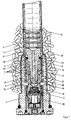
- Fig.1 Halbschnitt durch den unteren Teil eines Treibladungsanzünders,
- Fig. 2 Längsschnitt durch ein Flammleitrohr mit einer speziell ausgebildeten Abdichtung.
- 1 half section through the lower part of a propellant charge lighter,
- Fig. 2 longitudinal section through a flame guide tube with a specially designed seal.
In dem Bodenstück 1 eines Treibladungsanzünders ist ein elektrisch zündbares Primärzündelement 15 eingebaut, das eine Anzündladung 2 anzündet. Die sich dabei ausbildende Zündflamme wird durch einen Kanal 3 in einem Flammleitrohr 6 in die aus Tabletten aufgebaute Übertragungsladung 4 geführt. Die Übertragungsladung 4 wird von einem verbrennbaren Rohr 5 zusammengehalten. Das verbrennbare Rohr 5 ist teilweise in das Bodenstück 1 eingezogen, wobei es von innen her im unteren Bereich von einer metallischen Hülse 9, beispielsweise aus Cu Zn 37 F 37, abgestützt wird.An electrically ignitable primary ignition element 15, which ignites an ignition charge 2, is installed in the
Zwischen dem Flammleitrohr 6 und dem verbrennbaren Rohr 5 bzw. der Hülse 9 verbleibt ein Hohlraum 8, der weitgehend mit ringförmigen Treibmitteltabletten des Abtrennsatzes 7 ausgefüllt ist. Dieser Hohlraum 8 ist zur Übertragungsladung 4 hin, wie in Fig. 2 beschrieben, abgedichtet. Zur Verbesserung der Festigkeit sind das Bodenstück 1, die Hülse 9 und das Kopfteil 16 des Anzündstückes durch Spannhülsen 14 miteinander verbunden.A cavity 8 remains between the
Charakteristisch sind die Anfeuerungsbohrungen 13, durch die der Abtrennsatz 7 von außen durch das den Treibladungsanzünder umgebende Treibladungspulver 19 angezündet wird. Der Hohlraum 8 ist hier auf der dem Bodenstück 1 zugewandten Seite über einen weiteren Hohlraum 10 mit den hier vier gleichmäßig am Umfang verteilten Anfeuerungsbohrungen 13 verbunden.The
Gemäß der Erfindung ist das Anzünden der Abtrennladung 7 zeitlich stets mit einem bestimmten Treibladungsgasdruck gekoppelt, und das Abtrennen des verbrennbaren Rohres erfolgt mit großer Präzision.According to the invention, the ignition of the separating
Zum rückstandsfreien Abtrennen des in seiner Struktur bereits geschwächten verbrennbaren Rohres 5 sollte am besten überhaupt kein Dichtring 12 vorhanden sein, damit die Schwaden des Abtrennsatzes von der metallischen Hülse 9 und dem Flammleitrohr 6 geführt über einen Spalt 20 zwischen Flammleitrohrkopf 11 und Hülse 9 an den Bereich 21 des verbrennbaren Rohres 5 an den Oberkanten des Bodenstückes 1 gelangen können, der Sollbruchstelle. Eine bevorzugte Ausführungsform des Flammleitrohres 6 mit einer speziellen Dichtung im Flammleitrohrkopf 11 ist in Figur 2 dargestellt, wobei die Lagen der Oberkanten von metallischer Hülse 9 und Bodenstück 1 auf der linken Seite mit eingezeichnet sind. Die Nut 18 hat hier näherungsweise einen trapezförmigen Querschnitt, wobei der Übergang nach oben zur Übertragungsladung hin abgerundet und konisch verläuft, nach unten zum Bodenstück 1 hin stößt die Nut 18 senkrecht an der Hülse 9 an. Der Rundschnurring 12 soll im eingebauten Zustand um ca. 3-20% verformt werden. Die metallische Hülse 9 soll so weit reichen, daß sie den Dichtring 12 nach außen abzustützen vermag. Der Spalt 20 zwischen der metallischen Hülse 9 und dem Flammleitrohrkopf 11 beträgt 0,75 mm. Der Bereich 21 zwischen der Oberkante des Bodenstückes 1 und dem Auslauf 22 der Nut 18 hat eine Breite zwischen 0,8 mm und 2,5 mm, vorzugsweise zwischen 1,3 mm und 2,0 mm. Der Auslaufwinkel 24 der dem Bodenstück 1 abgewandten Seite des Trapezes beträgt 45° und der Krümmungsradius der Abrundung 25 ist 3 mm.For residue-free separation of the combustible tube 5, which is already weakened in its structure, it is best if there is no
Claims (14)
Priority Applications (1)
| Application Number | Priority Date | Filing Date | Title |
|---|---|---|---|
| AT89114499T ATE75309T1 (en) | 1988-09-01 | 1989-08-05 | PRIMER WITH POWDER-INITIATED SEPARATION CHARGE. |
Applications Claiming Priority (2)
| Application Number | Priority Date | Filing Date | Title |
|---|---|---|---|
| DE3829657A DE3829657A1 (en) | 1988-09-01 | 1988-09-01 | DRIVE CHARGE LIGHT WITH DISCONNECTED FROM DRIVE POWDER |
| DE3829657 | 1988-09-01 |
Publications (2)
| Publication Number | Publication Date |
|---|---|
| EP0361032A1 EP0361032A1 (en) | 1990-04-04 |
| EP0361032B1 true EP0361032B1 (en) | 1992-04-22 |
Family
ID=6362048
Family Applications (1)
| Application Number | Title | Priority Date | Filing Date |
|---|---|---|---|
| EP89114499A Expired - Lifetime EP0361032B1 (en) | 1988-09-01 | 1989-08-05 | Propellant charge igniter with a cutting charge ignited by the propellant charge powder |
Country Status (4)
| Country | Link |
|---|---|
| US (1) | US4913052A (en) |
| EP (1) | EP0361032B1 (en) |
| AT (1) | ATE75309T1 (en) |
| DE (2) | DE3829657A1 (en) |
Families Citing this family (5)
| Publication number | Priority date | Publication date | Assignee | Title |
|---|---|---|---|---|
| DE4240273A1 (en) * | 1992-12-01 | 1994-06-09 | Dynamit Nobel Ag | Propellant lighter |
| FR2806789B1 (en) * | 2000-03-23 | 2002-06-07 | Giat Ind Sa | IGNITION TUBE FOR ARTILLERY AMMUNITION |
| US6672215B2 (en) | 2001-10-17 | 2004-01-06 | Textron Systems Corporation | Constant output high-precision microcapillary pyrotechnic initiator |
| US6761116B2 (en) | 2001-10-17 | 2004-07-13 | Textron Sytems Corporation | Constant output high-precision microcapillary pyrotechnic initiator |
| WO2010055088A1 (en) * | 2008-11-13 | 2010-05-20 | Ruag Ammotec Gmbh | Pyrotechnic igniter |
Family Cites Families (2)
| Publication number | Priority date | Publication date | Assignee | Title |
|---|---|---|---|---|
| DE3226269C2 (en) * | 1982-07-14 | 1986-04-17 | Dynamit Nobel Ag, 5210 Troisdorf | Partially combustible propellant charge lighter |
| DE3502166A1 (en) * | 1985-01-23 | 1986-07-24 | Dynamit Nobel Ag, 5210 Troisdorf | PARTLY COMBUSTIBLE DRIVE CHARGER |
-
1988
- 1988-09-01 DE DE3829657A patent/DE3829657A1/en not_active Withdrawn
-
1989
- 1989-08-05 DE DE8989114499T patent/DE58901236D1/en not_active Expired - Lifetime
- 1989-08-05 EP EP89114499A patent/EP0361032B1/en not_active Expired - Lifetime
- 1989-08-05 AT AT89114499T patent/ATE75309T1/en not_active IP Right Cessation
- 1989-08-29 US US07/399,949 patent/US4913052A/en not_active Expired - Fee Related
Also Published As
| Publication number | Publication date |
|---|---|
| ATE75309T1 (en) | 1992-05-15 |
| EP0361032A1 (en) | 1990-04-04 |
| US4913052A (en) | 1990-04-03 |
| DE3829657A1 (en) | 1990-03-08 |
| DE58901236D1 (en) | 1992-05-27 |
Similar Documents
| Publication | Publication Date | Title |
|---|---|---|
| DE69717338T2 (en) | Pyrophoric countermeasure light set | |
| DE2914049C2 (en) | cartridge | |
| EP0656522B1 (en) | Cartridge case | |
| DE3872805T2 (en) | CONNECTION RING BETWEEN BULLET AND BULLET SLEEVE. | |
| EP0361032B1 (en) | Propellant charge igniter with a cutting charge ignited by the propellant charge powder | |
| DE2648267C2 (en) | ||
| EP3259549B1 (en) | Tracer ammunition | |
| EP0600385B1 (en) | Igniter for propulsive charge | |
| DE3049082C2 (en) | Safety device for a detonator | |
| EP0100840B1 (en) | Partially combustible igniter for a propellant charge | |
| DE4337444A1 (en) | Improvements in or related to solid fuel burners | |
| DE2324482B2 (en) | Cartridge case for blow detonation | |
| EP3137845B1 (en) | Cartridge with safety fuse in the drive system, and method for producing it | |
| DE4327098C2 (en) | Valve arrangement for a gas pressure accumulator | |
| DE3701145A1 (en) | DRIVE CHARGE LIGHT | |
| DE69519947T2 (en) | CARTRIDGE BAG | |
| EP0237711B1 (en) | Primer for a cartridge propellant charge | |
| EP3625515B1 (en) | Propelling system for cartidge ammunition | |
| DE2709705A1 (en) | ROCKET DRIVE | |
| DE69003854T2 (en) | Propellant igniter. | |
| DE4331395A1 (en) | Drive reflector for projectile for RAM accelerator - comprises projectile accelerated in accelerator comprising tubular pre-accelerator, followed by accelerator tubes based on RAM effect. | |
| EP0795114A1 (en) | Cartridge | |
| DE3872215T2 (en) | PARTITION WASHER WITH TARGET BREAKDOWNS FOR ROCKETS WITH SOLID FUELS. | |
| DE3139525A1 (en) | Process for igniting a gas-generating propellant-charge cartridge and construction of such a cartridge | |
| DE3837839A1 (en) | Propellant charge casing having a permeable shaft |
Legal Events
| Date | Code | Title | Description |
|---|---|---|---|
| PUAI | Public reference made under article 153(3) epc to a published international application that has entered the european phase |
Free format text: ORIGINAL CODE: 0009012 |
|
| AK | Designated contracting states |
Kind code of ref document: A1 Designated state(s): AT BE CH DE ES FR GB IT LI NL SE |
|
| 17P | Request for examination filed |
Effective date: 19900430 |
|
| 17Q | First examination report despatched |
Effective date: 19910722 |
|
| GRAA | (expected) grant |
Free format text: ORIGINAL CODE: 0009210 |
|
| AK | Designated contracting states |
Kind code of ref document: B1 Designated state(s): AT BE CH DE ES FR GB IT LI NL SE |
|
| PG25 | Lapsed in a contracting state [announced via postgrant information from national office to epo] |
Ref country code: SE Effective date: 19920422 Ref country code: BE Effective date: 19920422 Ref country code: NL Effective date: 19920422 Ref country code: GB Effective date: 19920422 Ref country code: ES Free format text: THE PATENT HAS BEEN ANNULLED BY A DECISION OF A NATIONAL AUTHORITY Effective date: 19920422 Ref country code: FR Effective date: 19920422 Ref country code: IT Free format text: LAPSE BECAUSE OF FAILURE TO SUBMIT A TRANSLATION OF THE DESCRIPTION OR TO PAY THE FEE WITHIN THE PRE;WARNING: LAPSES OF ITALIAN PATENTS WITH EFFECTIVE DATE BEFORE 2007 MAY HAVE OCCURRED AT ANY TIME BEFORE 2007. THE CORRECT EFFECTIVE DATE MAY BE DIFFERENT FROM THE ONE RECORDED.SCRIBED TIME-LIMIT Effective date: 19920422 |
|
| REF | Corresponds to: |
Ref document number: 75309 Country of ref document: AT Date of ref document: 19920515 Kind code of ref document: T |
|
| REF | Corresponds to: |
Ref document number: 58901236 Country of ref document: DE Date of ref document: 19920527 |
|
| PG25 | Lapsed in a contracting state [announced via postgrant information from national office to epo] |
Ref country code: AT Effective date: 19920805 |
|
| PG25 | Lapsed in a contracting state [announced via postgrant information from national office to epo] |
Ref country code: LI Effective date: 19920831 Ref country code: CH Effective date: 19920831 |
|
| EN | Fr: translation not filed | ||
| NLV1 | Nl: lapsed or annulled due to failure to fulfill the requirements of art. 29p and 29m of the patents act | ||
| GBV | Gb: ep patent (uk) treated as always having been void in accordance with gb section 77(7)/1977 [no translation filed] | ||
| PLBE | No opposition filed within time limit |
Free format text: ORIGINAL CODE: 0009261 |
|
| STAA | Information on the status of an ep patent application or granted ep patent |
Free format text: STATUS: NO OPPOSITION FILED WITHIN TIME LIMIT |
|
| 26N | No opposition filed | ||
| REG | Reference to a national code |
Ref country code: CH Ref legal event code: PL |
|
| PGFP | Annual fee paid to national office [announced via postgrant information from national office to epo] |
Ref country code: DE Payment date: 19930913 Year of fee payment: 5 |
|
| PG25 | Lapsed in a contracting state [announced via postgrant information from national office to epo] |
Ref country code: DE Effective date: 19950503 |