EP0361032B1 - Allumeur de charge propulsive avec charge de découpage à amorçage par la poudre de la charge propulsive - Google Patents
Allumeur de charge propulsive avec charge de découpage à amorçage par la poudre de la charge propulsive Download PDFInfo
- Publication number
- EP0361032B1 EP0361032B1 EP89114499A EP89114499A EP0361032B1 EP 0361032 B1 EP0361032 B1 EP 0361032B1 EP 89114499 A EP89114499 A EP 89114499A EP 89114499 A EP89114499 A EP 89114499A EP 0361032 B1 EP0361032 B1 EP 0361032B1
- Authority
- EP
- European Patent Office
- Prior art keywords
- charge
- flame
- base piece
- igniter according
- casing
- Prior art date
- Legal status (The legal status is an assumption and is not a legal conclusion. Google has not performed a legal analysis and makes no representation as to the accuracy of the status listed.)
- Expired - Lifetime
Links
- 239000003380 propellant Substances 0.000 title abstract description 23
- 239000000843 powder Substances 0.000 title description 3
- 238000000926 separation method Methods 0.000 claims abstract description 23
- 239000007789 gas Substances 0.000 claims abstract description 17
- 238000007789 sealing Methods 0.000 claims abstract description 6
- 238000002485 combustion reaction Methods 0.000 claims description 2
- 239000002184 metal Substances 0.000 claims 5
- 241000826860 Trapezium Species 0.000 claims 4
- 229920003023 plastic Polymers 0.000 claims 1
- 239000004033 plastic Substances 0.000 claims 1
- 230000037452 priming Effects 0.000 abstract 1
- 238000010304 firing Methods 0.000 description 3
- 238000011161 development Methods 0.000 description 2
- 230000018109 developmental process Effects 0.000 description 2
- 229910017518 Cu Zn Inorganic materials 0.000 description 1
- 239000000567 combustion gas Substances 0.000 description 1
- 230000001419 dependent effect Effects 0.000 description 1
- 230000002349 favourable effect Effects 0.000 description 1
- 230000035515 penetration Effects 0.000 description 1
- 230000000750 progressive effect Effects 0.000 description 1
- 230000007704 transition Effects 0.000 description 1
Images

Classifications
-
- F—MECHANICAL ENGINEERING; LIGHTING; HEATING; WEAPONS; BLASTING
- F42—AMMUNITION; BLASTING
- F42C—AMMUNITION FUZES; ARMING OR SAFETY MEANS THEREFOR
- F42C19/00—Details of fuzes
- F42C19/08—Primers; Detonators
- F42C19/0823—Primers or igniters for the initiation or the propellant charge in a cartridged ammunition
- F42C19/0826—Primers or igniters for the initiation or the propellant charge in a cartridged ammunition comprising an elongated perforated tube, i.e. flame tube, for the transmission of the initial energy to the propellant charge, e.g. used for artillery shells and kinetic energy penetrators
-
- F—MECHANICAL ENGINEERING; LIGHTING; HEATING; WEAPONS; BLASTING
- F42—AMMUNITION; BLASTING
- F42C—AMMUNITION FUZES; ARMING OR SAFETY MEANS THEREFOR
- F42C19/00—Details of fuzes
- F42C19/08—Primers; Detonators
- F42C19/0823—Primers or igniters for the initiation or the propellant charge in a cartridged ammunition
- F42C19/083—Primers or igniters for the initiation or the propellant charge in a cartridged ammunition characterised by the shape and configuration of the base element embedded in the cartridge bottom, e.g. the housing for the squib or percussion cap
Definitions
- the invention relates to a propellant lighter containing a base piece and an igniter head part with an igniter charge, a flame guide tube connected to the igniter charge with a flame guide tube head to a transfer charge surrounded by a combustible tube with blowout holes, and a cavity containing a separating set between the flame guide tube and a metallic sleeve running under the combustible tube, the cavity extending somewhat beyond the upper edge of the metallic sleeve and the base piece, and the combustible tube being separated off by gases from the separating set directly above the upper edge of the base piece.
- a partially combustible propellant lighter is known from DE 3 502 166 C2.
- the separating set is intended to completely separate a combustible tube which envelops the transfer charge from the base piece.
- the separation set is ignited by one or more bores in the head of the flame guide tube from back-flowing combustion gases from the tablet column of the transfer charge. Valve disks are present in the flame guide tube head, which fold over when the pressure rises due to the burning off of the separation set. With progressive combustion of the separation set, the pressure in the cavity rises so much that the desired separation of the combustible tube finally occurs immediately above the upper edge of the base piece.
- Burning off the transfer charge depends on the temperature. As a result, in particular at temperatures below 0 ° C., the separating charge can be ignited too early by back-flowing gas from the transfer charge, which occurs when the charge is sharp Shot causes disturbances in ballistics; there may also be a flare in the area where the cannon is locked.
- the object of the invention is a precise, adapted to the ambient temperature lighting of the separation set.
- a propellant lighter which is characterized by one or more connection holes between the cavity containing the separation set and the outside of the propellant charge lighter and a valve-like seal on the flame guide tube head to the sleeve, which on the one hand the direct entry of gases of the transfer charge into prevents the cavity, which, however, allows the gases of the separation set to escape through the combustible tube above the top channel of the base piece.
- the separating charge is therefore no longer ignited directly by the back-flowing gases of the tablet column of the transfer charge, since the rate of development of the propellant gas is temperature-dependent. Only when a certain propellant pressure has built up, i.e. If the burn-off only takes place regardless of the ambient temperature according to the specific properties of the propellant charge, the detachment charge is ignited from the outside through the casing via the firing holes. While the separation set was previously ignited 2 to 4 ms after the primary ignition element had been ignited and the start of pressure build-up due to the propellant charge gases started considerably later depending on the ambient temperature, it is now impossible to ignite the separation set too early. It is in a fixed time relationship with the pressure increase or the maximum pressure of the propellant gases.
- the seal on the flame guide tube head has the opposite function to that of the partially combustible propellant lighter known from DE 3 502 166 C2.
- the groove when viewed in cross section, has the shape of a trapezoid with the parallel sides parallel to the sleeve.
- a round cord ring rests on the rear surface of the sides of the trapezoid facing the base piece. It is important that the metallic sleeve supports the round cord ring from the outside in this "sealing position". Penetration of swaths of the transfer charge into the cavity with the separating charge is thus excluded.
- the seal on the flame guide tube head should be removed.
- the round cord ring is pushed so high in the groove by the gases of the separation charge that the gases can cut off the already weakened combustible tube above the base piece without leaving any residue. For this reason, it is favorable if the side of the trapezoid facing the transfer charge is chamfered or rounded. So there is always perfect barrel clearance after the shot.
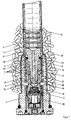
- An electrically ignitable primary ignition element 15, which ignites an ignition charge 2, is installed in the base piece 1 of a propellant charge lighter.
- the pilot flame that forms is guided through a channel 3 in a flame guide tube 6 into the transfer charge 4 made up of tablets.
- the transfer charge 4 is held together by a combustible tube 5.
- the combustible tube 5 is partially drawn into the bottom piece 1, with it from the inside in the lower region is supported by a metallic sleeve 9, for example made of Cu Zn 37 F 37.
- a cavity 8 remains between the flame guide tube 6 and the combustible tube 5 or the sleeve 9, which cavity is largely filled with annular propellant tablets of the separation set 7. This cavity 8 is sealed off from the transfer charge 4, as described in FIG. 2.
- the base piece 1, the sleeve 9 and the head part 16 of the ignition piece are connected to one another by clamping sleeves 14.
- the firing bores 13 are characteristic, through which the separation set 7 is ignited from the outside by the propellant powder 19 surrounding the propellant charge lighter.
- the cavity 8 is connected here on the side facing the base piece 1 via a further cavity 10 to the four firing holes 13, which are evenly distributed over the circumference here.
- the ignition of the separating charge 7 is always time-coupled with a certain propellant gas pressure, and the combustible tube is cut off with great precision.
- the groove 18 here has approximately a trapezoidal cross-section, the transition upwards towards the transfer charge being rounded and conical, after at the bottom towards the bottom piece 1, the groove 18 abuts the sleeve 9 vertically.
- the round cord ring 12 should be deformed by about 3-20% when installed.
- the metallic sleeve 9 should extend so far that it can support the sealing ring 12 to the outside.
- the gap 20 between the metallic sleeve 9 and the flame guide tube head 11 is 0.75 mm.
- the area 21 between the upper edge of the base piece 1 and the outlet 22 of the groove 18 has a width between 0.8 mm and 2.5 mm, preferably between 1.3 mm and 2.0 mm.
- the outlet angle 24 of the side of the trapezoid facing away from the base piece 1 is 45 ° and the radius of curvature of the rounding 25 is 3 mm.
Landscapes
- Engineering & Computer Science (AREA)
- General Engineering & Computer Science (AREA)
- Lighters Containing Fuel (AREA)
- Portable Nailing Machines And Staplers (AREA)
- Fire-Extinguishing By Fire Departments, And Fire-Extinguishing Equipment And Control Thereof (AREA)
- Eye Examination Apparatus (AREA)
- Vending Machines For Individual Products (AREA)
- Seal Device For Vehicle (AREA)
- Air Bags (AREA)
Claims (14)
Priority Applications (1)
| Application Number | Priority Date | Filing Date | Title |
|---|---|---|---|
| AT89114499T ATE75309T1 (de) | 1988-09-01 | 1989-08-05 | Treibladungsanzuender mit vom treibladungspulver initiierter abtrennladung. |
Applications Claiming Priority (2)
| Application Number | Priority Date | Filing Date | Title |
|---|---|---|---|
| DE3829657A DE3829657A1 (de) | 1988-09-01 | 1988-09-01 | Treibladungsanzuender mit vom treibladungspulver initiierter abtrennladung |
| DE3829657 | 1988-09-01 |
Publications (2)
| Publication Number | Publication Date |
|---|---|
| EP0361032A1 EP0361032A1 (fr) | 1990-04-04 |
| EP0361032B1 true EP0361032B1 (fr) | 1992-04-22 |
Family
ID=6362048
Family Applications (1)
| Application Number | Title | Priority Date | Filing Date |
|---|---|---|---|
| EP89114499A Expired - Lifetime EP0361032B1 (fr) | 1988-09-01 | 1989-08-05 | Allumeur de charge propulsive avec charge de découpage à amorçage par la poudre de la charge propulsive |
Country Status (4)
| Country | Link |
|---|---|
| US (1) | US4913052A (fr) |
| EP (1) | EP0361032B1 (fr) |
| AT (1) | ATE75309T1 (fr) |
| DE (2) | DE3829657A1 (fr) |
Families Citing this family (5)
| Publication number | Priority date | Publication date | Assignee | Title |
|---|---|---|---|---|
| DE4240273A1 (de) * | 1992-12-01 | 1994-06-09 | Dynamit Nobel Ag | Treibladungsanzünder |
| FR2806789B1 (fr) * | 2000-03-23 | 2002-06-07 | Giat Ind Sa | Tube allumeur pour une munition d'artillerie |
| US6672215B2 (en) | 2001-10-17 | 2004-01-06 | Textron Systems Corporation | Constant output high-precision microcapillary pyrotechnic initiator |
| US6761116B2 (en) | 2001-10-17 | 2004-07-13 | Textron Sytems Corporation | Constant output high-precision microcapillary pyrotechnic initiator |
| WO2010055088A1 (fr) * | 2008-11-13 | 2010-05-20 | Ruag Ammotec Gmbh | Allumeur pyrotechnique |
Family Cites Families (2)
| Publication number | Priority date | Publication date | Assignee | Title |
|---|---|---|---|---|
| DE3226269C2 (de) * | 1982-07-14 | 1986-04-17 | Dynamit Nobel Ag, 5210 Troisdorf | Teilverbrennbarer Treibladungsanzünder |
| DE3502166A1 (de) * | 1985-01-23 | 1986-07-24 | Dynamit Nobel Ag, 5210 Troisdorf | Teilverbrennbarer treibladungsanzuender |
-
1988
- 1988-09-01 DE DE3829657A patent/DE3829657A1/de not_active Withdrawn
-
1989
- 1989-08-05 DE DE8989114499T patent/DE58901236D1/de not_active Expired - Lifetime
- 1989-08-05 EP EP89114499A patent/EP0361032B1/fr not_active Expired - Lifetime
- 1989-08-05 AT AT89114499T patent/ATE75309T1/de not_active IP Right Cessation
- 1989-08-29 US US07/399,949 patent/US4913052A/en not_active Expired - Fee Related
Also Published As
| Publication number | Publication date |
|---|---|
| ATE75309T1 (de) | 1992-05-15 |
| EP0361032A1 (fr) | 1990-04-04 |
| US4913052A (en) | 1990-04-03 |
| DE3829657A1 (de) | 1990-03-08 |
| DE58901236D1 (de) | 1992-05-27 |
Similar Documents
| Publication | Publication Date | Title |
|---|---|---|
| DE69717338T2 (de) | Pyrophorischer Gegenmassnahmenleuchtsatz | |
| DE2914049C2 (de) | Patrone | |
| EP0656522B1 (fr) | Douille pour cartouche | |
| DE3872805T2 (de) | Verbindungsring zwischen geschoss und geschosshuelse. | |
| EP0361032B1 (fr) | Allumeur de charge propulsive avec charge de découpage à amorçage par la poudre de la charge propulsive | |
| DE2648267C2 (fr) | ||
| EP3259549B1 (fr) | Munition de traçage luminescente | |
| EP0600385B1 (fr) | Allumeur pour charge propulsive | |
| DE3049082C2 (de) | Sicherungseinrichtung für einen Zünder | |
| EP0100840B1 (fr) | Amorce partiellement combustible pour charge propulsive | |
| DE4337444A1 (de) | Verbesserungen bei bzw. im Zusammenhang mit Festtreibstoff-Brenneinrichtungen | |
| DE2324482B2 (de) | Patronenhülse für Schlagzundung | |
| EP3137845B1 (fr) | Cartouche avec fusible dans le système de propulsion et son procédé de fabrication | |
| DE4327098C2 (de) | Ventilanordnung für einen Gasdruckspeicher | |
| DE3701145A1 (de) | Treibladungsanzuender | |
| DE69519947T2 (de) | Patronenbeutel | |
| EP0237711B1 (fr) | Allumeur pour charge propulsive d'une cartouche | |
| EP3625515B1 (fr) | Sytème propulsif pour une munition en forme de cartouche | |
| DE2709705A1 (de) | Raketenantrieb | |
| DE69003854T2 (de) | Treibladungszünder. | |
| DE4331395A1 (de) | Treibspiegel für Geschoß für RAM-Beschleuniger und Geschoß mit einem solchen Treibspiegel | |
| EP0795114A1 (fr) | Cartouche | |
| DE3872215T2 (de) | Trennwandscheibe mit sollbruchstellen fuer raketen mit festen treibstoffen. | |
| DE3139525A1 (de) | Verfahren zum zuenden einer gaserzeugenden treibladungskartusche und konstruktion einer derartigen kartusche | |
| DE3837839A1 (de) | Treibladungshuelse mit durchlaessigem schaft |
Legal Events
| Date | Code | Title | Description |
|---|---|---|---|
| PUAI | Public reference made under article 153(3) epc to a published international application that has entered the european phase |
Free format text: ORIGINAL CODE: 0009012 |
|
| AK | Designated contracting states |
Kind code of ref document: A1 Designated state(s): AT BE CH DE ES FR GB IT LI NL SE |
|
| 17P | Request for examination filed |
Effective date: 19900430 |
|
| 17Q | First examination report despatched |
Effective date: 19910722 |
|
| GRAA | (expected) grant |
Free format text: ORIGINAL CODE: 0009210 |
|
| AK | Designated contracting states |
Kind code of ref document: B1 Designated state(s): AT BE CH DE ES FR GB IT LI NL SE |
|
| PG25 | Lapsed in a contracting state [announced via postgrant information from national office to epo] |
Ref country code: SE Effective date: 19920422 Ref country code: BE Effective date: 19920422 Ref country code: NL Effective date: 19920422 Ref country code: GB Effective date: 19920422 Ref country code: ES Free format text: THE PATENT HAS BEEN ANNULLED BY A DECISION OF A NATIONAL AUTHORITY Effective date: 19920422 Ref country code: FR Effective date: 19920422 Ref country code: IT Free format text: LAPSE BECAUSE OF FAILURE TO SUBMIT A TRANSLATION OF THE DESCRIPTION OR TO PAY THE FEE WITHIN THE PRE;WARNING: LAPSES OF ITALIAN PATENTS WITH EFFECTIVE DATE BEFORE 2007 MAY HAVE OCCURRED AT ANY TIME BEFORE 2007. THE CORRECT EFFECTIVE DATE MAY BE DIFFERENT FROM THE ONE RECORDED.SCRIBED TIME-LIMIT Effective date: 19920422 |
|
| REF | Corresponds to: |
Ref document number: 75309 Country of ref document: AT Date of ref document: 19920515 Kind code of ref document: T |
|
| REF | Corresponds to: |
Ref document number: 58901236 Country of ref document: DE Date of ref document: 19920527 |
|
| PG25 | Lapsed in a contracting state [announced via postgrant information from national office to epo] |
Ref country code: AT Effective date: 19920805 |
|
| PG25 | Lapsed in a contracting state [announced via postgrant information from national office to epo] |
Ref country code: LI Effective date: 19920831 Ref country code: CH Effective date: 19920831 |
|
| EN | Fr: translation not filed | ||
| NLV1 | Nl: lapsed or annulled due to failure to fulfill the requirements of art. 29p and 29m of the patents act | ||
| GBV | Gb: ep patent (uk) treated as always having been void in accordance with gb section 77(7)/1977 [no translation filed] | ||
| PLBE | No opposition filed within time limit |
Free format text: ORIGINAL CODE: 0009261 |
|
| STAA | Information on the status of an ep patent application or granted ep patent |
Free format text: STATUS: NO OPPOSITION FILED WITHIN TIME LIMIT |
|
| 26N | No opposition filed | ||
| REG | Reference to a national code |
Ref country code: CH Ref legal event code: PL |
|
| PGFP | Annual fee paid to national office [announced via postgrant information from national office to epo] |
Ref country code: DE Payment date: 19930913 Year of fee payment: 5 |
|
| PG25 | Lapsed in a contracting state [announced via postgrant information from national office to epo] |
Ref country code: DE Effective date: 19950503 |