EP0361076A1 - Soupape commandée par la température - Google Patents
Soupape commandée par la température Download PDFInfo
- Publication number
- EP0361076A1 EP0361076A1 EP89115503A EP89115503A EP0361076A1 EP 0361076 A1 EP0361076 A1 EP 0361076A1 EP 89115503 A EP89115503 A EP 89115503A EP 89115503 A EP89115503 A EP 89115503A EP 0361076 A1 EP0361076 A1 EP 0361076A1
- Authority
- EP
- European Patent Office
- Prior art keywords
- valve
- temperature
- expansion
- valve according
- temperature sensor
- Prior art date
- Legal status (The legal status is an assumption and is not a legal conclusion. Google has not performed a legal analysis and makes no representation as to the accuracy of the status listed.)
- Withdrawn
Links
Images

Classifications
-
- G—PHYSICS
- G05—CONTROLLING; REGULATING
- G05D—SYSTEMS FOR CONTROLLING OR REGULATING NON-ELECTRIC VARIABLES
- G05D23/00—Control of temperature
- G05D23/01—Control of temperature without auxiliary power
- G05D23/12—Control of temperature without auxiliary power with sensing element responsive to pressure or volume changes in a confined fluid
- G05D23/125—Control of temperature without auxiliary power with sensing element responsive to pressure or volume changes in a confined fluid the sensing element being placed outside a regulating fluid flow
- G05D23/126—Control of temperature without auxiliary power with sensing element responsive to pressure or volume changes in a confined fluid the sensing element being placed outside a regulating fluid flow using a capillary tube
-
- G—PHYSICS
- G05—CONTROLLING; REGULATING
- G05D—SYSTEMS FOR CONTROLLING OR REGULATING NON-ELECTRIC VARIABLES
- G05D23/00—Control of temperature
- G05D23/19—Control of temperature characterised by the use of electric means
- G05D23/1919—Control of temperature characterised by the use of electric means characterised by the type of controller
- G05D23/1921—Control of temperature characterised by the use of electric means characterised by the type of controller using a thermal motor
Definitions
- the invention relates to a temperature-controlled valve with a valve seat arranged in a valve housing and a valve body that can be moved relative to it.
- An expansion sensor that can be used for this purpose is known, for example, from DE-PS 19 20 551. It contains a temperature sensor that is filled with liquid and is connected to an expansion socket via a capillary tube. The changes in shape of the expansion box that occur due to the change in temperature are used to open and close an electrical switch.
- the invention has for its object to provide a temperature-controlled valve that can respond to temperature changes with a simple structure without additional elements.
- valve body is connected via a valve actuating element to an expansion element of an expansion element having a temperature sensor such that the flow cross section of the valve also changes when the temperature measured by the temperature sensor changes.
- the invention thus creates a temperature-controlled valve in which a flow cross section can be changed as a function of a measured temperature.
- the refilling of the water can thus be controlled directly without additional aids, that is to say without the use of an additional solenoid valve and a voltage source for this.
- the arrangement is such that the valve opens when the temperature rises.
- valve is acted upon in the closing direction. If the expansion element should fail, the valve closes automatically, so that the valve proposed by the invention contains an intrinsic safety device.
- the expansion element has an adjusting screw.
- the coupling between the expansion member and the valve body can be changed by an adjusting device.
- the temperature sensor is filled with liquid and is connected via a capillary tube to the expansion element designed as an expansion socket.
- Such temperature sensors are often used in electric hot plates. Proven and existing components can therefore be used unchanged.
- the adjusting screw and / or the adjusting device act on the expansion socket.
- the expansion member acts directly on the actuating element of the valve.
- the actuating element of the valve can be designed as a rod which is guided axially displaceably in the valve and with one end of which rests on the expansion element, for example the expansion socket.
- the expansion element acts on the actuating element of the valve via a rocker or a rocker switch. In this way, different actuation paths can be compensated for particularly easily.
- the expansion element additionally acts on at least one electrical switch in a particularly simple manner. In this way, it becomes possible not only to control the supply of liquid with the help of the temperature sensor, but also as a function of certain temperatures also switch electrical equipment on or off.
- the temperature sensor is arranged adjacent to an electric heater. This can be either the electrical heating of a heated device which is present anyway, or it can be a separate heating provided only for the temperature sensor.
- the temperature-controlled valve proposed by the invention is to be used to regulate the water level in a steam generator.
- the invention proposes that the temperature sensor is arranged at the desired water level of the container and the valve is switched into a supply line for the container.
- the supply line can be, for example, the water line or a connecting line with a storage vessel. If the water is at the desired water level at the temperature sensor, it is cooled by the water. The expansion element contracts and the valve closes. However, if the water level drops, the heating of the device or its own heating heats the temperature sensor so that the liquid contained in it expands and the valve opens. As a result, water flows in and the water level rises again to the desired height. With a corresponding design of the valve and the expansion element, continuous control can be achieved in this way, so that a small water flow constantly flows into the container, which corresponds to the amount of water escaping through evaporation.
- thermosensors act on an expansion element.
- several capillary tubes with temperature sensors can be connected to one expansion socket. In this case an average occurs formation of temperatures. In this way, individual inaccurate measurement results can be determined.
- valve When the valve is connected to a supply line, it is desirable that the liquid not flow back into the supply area.
- the valve contains a check valve.
- the temperature-controlled valve proposed by the invention can be used to regulate the water level in containers, for example steam generators, in a bio sauna, in air conditioning units, in coffee or tea machines, in humidifiers, in inhalers and water baths.
- the valve can also be used in an oven in which conventional baking can be combined with steam heating.
- valve proposed by the invention directly as thermal protection for the automatic supply of cooling water without the need for an additional energy source such as a power supply for a solenoid valve.
- the valve shown in FIG. 1 contains a cylindrical valve housing 11, into which a bore 12 is made from one side, from below in FIG. 1.
- This bore 12 reduces its diameter in a funnel shape approximately in the middle of the valve housing and merges into a second cylindrical bore 13.
- This bore extends to the upper end of the valve housing.
- a tapered valve seat 14 is formed at the transition between the two bores of different diameters.
- a cylindrical extension 15 with an axial bore 16 is attached to the side of the valve housing 11.
- the axial bore 16 is arranged in the extension of a radially extending opening 17 of the valve housing 11, the radially extending opening 17 being arranged on the side of the valve seat 14 facing away from the inlet side 18 of the valve housing.
- a valve body 19 which cooperates with the valve seat 14.
- the valve body 19 In its area interacting with the valve seat 14, the valve body 19 is also conical. It is pressed onto the valve seat 14 by a coil spring 20.
- the coil spring 20 is supported on its side facing away from the valve seat 14.
- the valve body 19 has a cylindrical projection 21 with a reduced diameter, which forms a shoulder in the region of its outside, on which the helical spring 20 is supported. With its opposite end, the coil spring is supported on a ring 22 which is inserted, for example screwed, into the inlet-side end of the bore 12.
- the coil spring 20 acts on the valve body 19 in the closed position of the valve.
- valve actuating element 23 is slidably arranged in the longitudinal direction and protrudes upward from the valve housing 11. Seals, for example in the form of O-rings, are arranged between the valve actuating element 23 and the outer end of the bore 13 with the reduced diameter, which ensure that the valve is sealed at this point.
- a cage 24 is attached to the side of the valve housing 11 opposite the inlet side 18.
- An expansion member 25 of an expansion element is arranged within this cage 24.
- This expansion member 25 is designed as an expansion box 26 in the form of a flat cylindrical disc.
- the expansion box 26 is connected to a temperature sensor 28 via a capillary tube 27, the expansion box 26, the capillary tube 27 and the temperature sensor 28 being filled with a liquid.
- the temperature sensor 28 has the shape of an elongated tube which tapers at both ends.
- the expansion socket 26 has an extension 29 in the region of its one end face, which is supported on an adjusting screw 30.
- the adjusting screw 30 is screwed into an end face 31 of the cage 24.
- the expansion socket 26 On the opposite side, the end face of the expansion socket 26 bears against the outer end of the valve actuating element 23. In the position shown, the expansion socket 26 is held by a coil spring 32, which extends around the outer end of the valve actuating element 23 between the inner end face of the cage 24 and the end face of the expansion socket 26.
- the temperature sensor 28 is arranged in the vicinity of, for example, an electrical heater. If current flows through the electric heater 33, the temperature sensor 28 heats up so that the liquid contained in it expands.
- the expansion of the liquid leads to an expansion of the expansion can 26, the two end faces of which are configured like membranes. In other words, the expansion of the liquid causes the expansion box 26 to become thicker. Since the expansion box cannot deform upwards in FIG. 1 by contact with the adjusting screw 30, the end face of the expansion box 26 opposite the adjusting screw 30 in FIG. 1 downwards, in other words onto the valve actuating element 23.
- the depressed valve actuating element 23 presses the valve body 19 away from the valve seat 14, so that an annular gap is formed between the two.
- the inlet side 18 of the valve housing 11 is now connected to a water line or a storage vessel for water, the water can now flow past the lifted valve body 19 and through the radial opening 17 into the axial bore 16 of the extension 15. From there, the liquid flows in the direction of arrow 34, for example, into the interior of a container and increases the water level in the container there. As soon as the electric heater 33 cools down again, the liquid in the temperature sensor 28 contracts again, so that the thickness of the expansion box decreases again. The coil spring 20 therefore presses the valve body 19 and the valve actuating element 23 upwards, insofar as this is made possible by the volume of the liquid within the expansion socket 26. As a result, the valve body 19 comes to rest on the valve seat 14 and the valve is closed.
- valve body 19 constructed in the same way as the valve body 19 could be used here Check valve may be arranged.
- the valve shown in FIG. 1 thus assigns a certain flow cross section of the valve to each temperature of the electric heater 33 above a certain starting temperature.
- the flow cross section through the valve is controlled as a function of the temperature of the electric heater 33.
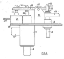
- Fig. 2 shows the structure of a modified embodiment of a valve according to the invention.
- the arrangement of the temperature sensor 28 and the capillary tube 27 is in principle the same as in the embodiment of FIG. 1, so that these parts are not shown again.
- the valve is built on a base plate 35.
- the base plate contains on one side, the upper side in FIG. 2, two bent-up tabs 36, to which a lever 38 is pivotably attached by means of a shaft 37.
- the lever is punched out of a sheet metal plate and bent at its edges to increase its stability.
- the expansion box 26 is held on the plate 35.
- One end face lies under one end 39 of the lever 38, the adjusting screw 30 being screwed into this end of the lever.
- It is a grub screw 40. This is screwed through a threaded opening of the lever 38 and additionally through a threaded opening in the folded end of the lever, the folded end being under a certain tension, so that the two in axial In the direction of spaced threaded openings cause a kind of self-locking of the adjusting screw 30.
- the lower end 41 of the grub screw 40 acts on one end face of the expansion box 26.
- a screw 42 is held on the plate 35.
- a screw 43 belongs to the screw spindle 42, which protrudes from the plate on both sides and rests in its area facing the expansion socket 26 on the end face of the expansion socket 26.
- the shaft 43 has a circular cross section flattened on one side.
- a gag or the like can be put on or screwed on, with the aid of which the shaft 43 can be rotated. The rotation of the shaft leads to its axial displacement, so that the expansion socket 26 can thereby be acted upon to a greater or lesser extent.
- the lever 38 On the opposite side of the shaft 37, the lever 38 has two further grub screws 44 at different distances from the shaft 37.
- the grub screw 44 with the shorter distance from the shaft 37 rests on the actuating element 23 of the valve, while the grub screw 44 with the greater distance rests on the actuating button 45 of an electrical switch 46.
- the switch 46 has two tabs 47, only one of which can be seen in FIG. 2.
- the valve which can be actuated by the grub screw 44 is constructed in principle in exactly the same way as the valve of FIG. 1, that is to say it contains an inlet connection 48 for connection to a water line or a water storage vessel and an outlet connection 49 which is connected to the line to the container in FIG which the liquid should be introduced.
- the mode of operation is again the same as in the embodiment of FIG. 1, ie when the liquid expands within the temperature sensor, the expansion box 26 deforms, which leads to a tilting of the lever 38.
- the valve is opened via the actuating element 23, so that liquid, for example water, of the inlet port 48 can flow into the outlet port 49.
- the screw spindle 42 an adjustment can be made so that an operator can select different operating modes.
- the screw spindle 42 can of course also receive a locking device, so that different positions can be locked.
- the switch 46 is now additionally actuated when the valve is opened.
- an additional heater can be switched on or off, or a pump that supports the flow through the valve.
- Both the response of the valve and the time at which the switch 46 is actuated can be set by the two grub screws.
- valve housing 11 can contain a plurality of outlet connections 49.
- Fig. 3 shows the arrangement of a valve proposed by the invention for level control of the water level in a container.
- the container 50 the wall of which is made of metal, for example, is heated on the underside of tubular heating elements 51.
- the container itself is filled with water.
- the temperature sensor 28 is attached to the container 50 in a heat-coupled manner on the outside. Since the distance between the temperature sensor 28 and the tubular heating elements 51 is too large, a further heating resistor 53 is arranged immediately adjacent to the temperature sensor and is continuously heated, for example. The power of the heating resistor 53 can be very small.
- the temperature sensor 28 is coupled to the schematically illustrated valve 54, the inlet side 55 of which is connected, for example, to the water line.
- the outlet side is connected to a line 56, the free end 57 of which ends at a point from where the water flows into the container 50 can. If the water assumes the nominal water level 52, the temperature of the temperature sensor 28 cannot rise significantly higher than the temperature of the water, that is to say around 100 ° C. If the water evaporates and the water level drops as a result, it can no longer cool the temperature sensor 28. This heats up under the action of the heating resistor 53. As a result, the temperature of the temperature sensor 28 rises, the liquid expands and the valve 54 is opened in the manner described. When the valve is open, water flows in, which flows through line 56 into container 50. The water level rises again until it reaches an area where the temperature sensor is cooled again. With appropriate inertia of the system, the valve can be controlled so that an equal amount of water continuously flows into the container as evaporates.
- the container is intended as a storage container for water, that is, it is not heated, and that water is removed by other measures, then a level regulation can also be achieved with the device shown. In this case, however, the output of the heating resistor 53 would have to be interpreted differently, since in this case the water would probably have a different temperature.
Landscapes
- Physics & Mathematics (AREA)
- General Physics & Mathematics (AREA)
- Engineering & Computer Science (AREA)
- Automation & Control Theory (AREA)
- Fluid Mechanics (AREA)
- Temperature-Responsive Valves (AREA)
Applications Claiming Priority (2)
| Application Number | Priority Date | Filing Date | Title |
|---|---|---|---|
| DE19883832737 DE3832737A1 (de) | 1988-09-27 | 1988-09-27 | Temperaturgesteuertes ventil |
| DE3832737 | 1988-09-27 |
Publications (1)
| Publication Number | Publication Date |
|---|---|
| EP0361076A1 true EP0361076A1 (fr) | 1990-04-04 |
Family
ID=6363788
Family Applications (1)
| Application Number | Title | Priority Date | Filing Date |
|---|---|---|---|
| EP89115503A Withdrawn EP0361076A1 (fr) | 1988-09-27 | 1989-08-23 | Soupape commandée par la température |
Country Status (2)
| Country | Link |
|---|---|
| EP (1) | EP0361076A1 (fr) |
| DE (1) | DE3832737A1 (fr) |
Cited By (1)
| Publication number | Priority date | Publication date | Assignee | Title |
|---|---|---|---|---|
| CN110774173A (zh) * | 2019-10-21 | 2020-02-11 | 吴嘉至 | 一种晶圆加工用自动卸料研磨机 |
Citations (7)
| Publication number | Priority date | Publication date | Assignee | Title |
|---|---|---|---|---|
| DE1013935B (de) * | 1955-07-08 | 1957-08-14 | Landis & Gyr Ag | Thermostatisch gesteuerter Durchflussregler |
| CH450779A (de) * | 1965-12-24 | 1968-01-31 | Danfoss As | Thermostatisch gesteuertes Ventil |
| GB1151198A (en) * | 1965-10-07 | 1969-05-07 | Paul Curti | Charge Regulator for use with Heat Storage Appliances |
| DE1295144B (de) * | 1961-03-17 | 1969-05-14 | Rowenta Metallwarenfab Gmbh | Kaffeemaschine mit elektrisch gesteuerter Wasserstandsregelung, insbesondere zur Verwendung in Flugzeugen |
| DE1500118A1 (de) * | 1965-08-12 | 1969-05-29 | Koch Fa Hermann | Sicherheitsventil |
| DE2219883A1 (de) * | 1972-04-22 | 1974-01-17 | Baumeister Kosmos Armaturen | Temperaturregler fuer ventile oder dergleichen |
| DE2841206A1 (de) * | 1978-09-22 | 1980-04-03 | Hansa Metallwerke Ag | Thermostatventil |
Family Cites Families (21)
| Publication number | Priority date | Publication date | Assignee | Title |
|---|---|---|---|---|
| CH315153A (de) * | 1953-08-01 | 1956-07-31 | Landis & Gyr Ag | Flüssigkeitsgefüllter Federthermostat mit mehreren Wärmefühlern |
| DE1209832B (de) * | 1962-10-18 | 1966-01-27 | Junkers & Co | Thermostatgesteuertes Ventil, insbesondere zum OEffnen oder Absperren der Gaszufuhr zu einem gasbeheizten Geraet |
| DE1204482B (de) * | 1962-11-13 | 1965-11-04 | Danfoss As | Thermostatisch betaetigtes Ventil (I) |
| DE1548933A1 (de) * | 1964-01-15 | 1970-02-26 | Dole Valve Co | Fluessigkeitsstand-Regelsystem |
| DE1600713B2 (de) * | 1967-05-13 | 1974-07-04 | Behr-Thomson Dehnstoffregler Gmbh, 7014 Kornwestheim | Zonenventil mit Verstelleinrichtung für umkehrbare Ventilverstellung |
| US3477498A (en) * | 1967-08-04 | 1969-11-11 | Ranco Inc | Liquid flow control valve mechanism |
| DE1920551C3 (de) * | 1969-04-23 | 1972-11-09 | Karl Fischer | Regler fuer Elektrowaermegeraete |
| DE7013301U (de) * | 1970-04-11 | 1970-09-17 | Braukmann Armaturen | Thermostatventil. |
| DE2613991C2 (de) * | 1976-04-01 | 1977-10-27 | Danfoss A/S, Nordborg (Danemark) | Therniostatische Betätigungsvorrichtung für ein Heizmittelventil |
| DE2753845C3 (de) * | 1977-11-30 | 1981-02-12 | Joh. Vaillant Gmbh U. Co, 5630 Remscheid | Thermostatisches Ventil |
| IT1051752B (it) * | 1978-02-28 | 1981-05-20 | Bortolan L | Valvola automatica di scarico rapido a elemento termosensibile |
| DE2927321A1 (de) * | 1979-07-06 | 1981-01-15 | Manfred Luik | Steuergeraet zum zeitabhaengigen betaetigen eines ventils |
| DE3000388A1 (de) * | 1980-01-07 | 1981-07-09 | Manfred 7250 Leonberg Luik | Verfahren und vorrichtung zum verbessern eines thermostaten |
| JPS5947186B2 (ja) * | 1980-01-17 | 1984-11-17 | 本田技研工業株式会社 | サ−モバルブ |
| DE3101560C2 (de) * | 1981-01-20 | 1986-06-19 | Afriso-Euro-Index GmbH, 7129 Güglingen | Temperaturgesteuertes Sicherheitsventil |
| DE3102311C2 (de) * | 1981-01-24 | 1982-10-14 | Danfoss A/S, 6430 Nordborg | Ferntemperaturfühler mit Dehnstoff |
| DE3127545A1 (de) * | 1981-07-11 | 1983-01-20 | Armaturenfabrik und Metallgießerei Koch und Müller GmbH, 4250 Bottrop | Absperrarmatur fuer insbesondere gasleitungen |
| GB2114741A (en) * | 1982-02-10 | 1983-08-24 | Loomhurst Ltd | Actuators |
| CH656687A5 (de) * | 1982-08-30 | 1986-07-15 | Elektrowatt Ag | Regelventil mit einem stetig wirkenden elektromagnetischen stellantrieb. |
| DE3337426A1 (de) * | 1983-10-14 | 1985-04-25 | Wella Ag, 6100 Darmstadt | Thermostat fuer heizkoerperventil |
| GB2186459B (en) * | 1986-02-12 | 1989-11-08 | Stc Plc | Optical actuator |
-
1988
- 1988-09-27 DE DE19883832737 patent/DE3832737A1/de not_active Withdrawn
-
1989
- 1989-08-23 EP EP89115503A patent/EP0361076A1/fr not_active Withdrawn
Patent Citations (7)
| Publication number | Priority date | Publication date | Assignee | Title |
|---|---|---|---|---|
| DE1013935B (de) * | 1955-07-08 | 1957-08-14 | Landis & Gyr Ag | Thermostatisch gesteuerter Durchflussregler |
| DE1295144B (de) * | 1961-03-17 | 1969-05-14 | Rowenta Metallwarenfab Gmbh | Kaffeemaschine mit elektrisch gesteuerter Wasserstandsregelung, insbesondere zur Verwendung in Flugzeugen |
| DE1500118A1 (de) * | 1965-08-12 | 1969-05-29 | Koch Fa Hermann | Sicherheitsventil |
| GB1151198A (en) * | 1965-10-07 | 1969-05-07 | Paul Curti | Charge Regulator for use with Heat Storage Appliances |
| CH450779A (de) * | 1965-12-24 | 1968-01-31 | Danfoss As | Thermostatisch gesteuertes Ventil |
| DE2219883A1 (de) * | 1972-04-22 | 1974-01-17 | Baumeister Kosmos Armaturen | Temperaturregler fuer ventile oder dergleichen |
| DE2841206A1 (de) * | 1978-09-22 | 1980-04-03 | Hansa Metallwerke Ag | Thermostatventil |
Cited By (1)
| Publication number | Priority date | Publication date | Assignee | Title |
|---|---|---|---|---|
| CN110774173A (zh) * | 2019-10-21 | 2020-02-11 | 吴嘉至 | 一种晶圆加工用自动卸料研磨机 |
Also Published As
| Publication number | Publication date |
|---|---|
| DE3832737A1 (de) | 1990-03-29 |
Similar Documents
| Publication | Publication Date | Title |
|---|---|---|
| DE2056072C2 (de) | Thermostatisch gesteuertes Mischventil für Warm- und Kaltwasser | |
| DE2548650C3 (fr) | ||
| DE3140472A1 (de) | "vorrichtung zum betaetigen eines unter der wirkung einer rueckstellfeder stehenden bolzens" | |
| EP3280934B1 (fr) | Agencement avec vanne et actionneur | |
| WO1999022175A1 (fr) | Regulateur de gaz | |
| EP1034362A1 (fr) | Soupape thermostatique montee dans le circuit de refroidissement d'un moteur a combustion interne | |
| DE2802803C2 (fr) | ||
| EP2048564A2 (fr) | Intervalle de réglage réglable | |
| EP0361076A1 (fr) | Soupape commandée par la température | |
| DE2936027C2 (fr) | ||
| DE2127354A1 (fr) | ||
| DE3610968C2 (de) | Blockiervorrichtung für die Tür einer Waschmaschine, insbesondere einer Haushaltswaschmaschine | |
| DE2414812A1 (de) | Ausdehnungsdose fuer temperaturempfindliche systeme | |
| DE1550412A1 (de) | Mischventil | |
| DE69707335T2 (de) | Zweiwege-Steuerventil mit variablem Durchtrittsquerschnitt für einen Kältekreislauf | |
| DE2821094C3 (de) | Thermostatisch geregeltes Mischventil | |
| DE10139197A1 (de) | Thermostatventil | |
| EP0013993B1 (fr) | Régulateur de pression | |
| DE29905204U1 (de) | Gasregelarmatur | |
| DE10106257B4 (de) | Vorrichtung zum Betätigen eines Ventils | |
| EP0252252A2 (fr) | Appareil de production d'eau chaude sanitaire | |
| DE10312724B4 (de) | Durchlauferhitzer | |
| EP0997685A2 (fr) | Raccord de buse pour un brûleur à pulvérisation de fuel sous pression et vanne d'arrêt pour un tel raccord de buse | |
| EP0634596A1 (fr) | Mitigeur à 3 voies, à température contrôlée | |
| DE1551960A1 (de) | Gasregelgeraet |
Legal Events
| Date | Code | Title | Description |
|---|---|---|---|
| PUAI | Public reference made under article 153(3) epc to a published international application that has entered the european phase |
Free format text: ORIGINAL CODE: 0009012 |
|
| AK | Designated contracting states |
Kind code of ref document: A1 Designated state(s): DE ES FR GB IT |
|
| 17P | Request for examination filed |
Effective date: 19900920 |
|
| STAA | Information on the status of an ep patent application or granted ep patent |
Free format text: STATUS: THE APPLICATION IS DEEMED TO BE WITHDRAWN |
|
| 18D | Application deemed to be withdrawn |
Effective date: 19920303 |