EP0361090B1 - Dispositif pour remplir du caillé en quantités dosées - Google Patents
Dispositif pour remplir du caillé en quantités dosées Download PDFInfo
- Publication number
- EP0361090B1 EP0361090B1 EP89115694A EP89115694A EP0361090B1 EP 0361090 B1 EP0361090 B1 EP 0361090B1 EP 89115694 A EP89115694 A EP 89115694A EP 89115694 A EP89115694 A EP 89115694A EP 0361090 B1 EP0361090 B1 EP 0361090B1
- Authority
- EP
- European Patent Office
- Prior art keywords
- metering
- cylinders
- metering cylinders
- funnel
- curd
- Prior art date
- Legal status (The legal status is an assumption and is not a legal conclusion. Google has not performed a legal analysis and makes no representation as to the accuracy of the status listed.)
- Expired - Lifetime
Links
- 235000013351 cheese Nutrition 0.000 claims description 36
- 239000005862 Whey Substances 0.000 claims description 3
- 102000007544 Whey Proteins Human genes 0.000 claims description 3
- 108010046377 Whey Proteins Proteins 0.000 claims description 3
- 238000007599 discharging Methods 0.000 claims 1
- 239000007921 spray Substances 0.000 description 2
- 238000004140 cleaning Methods 0.000 description 1
- 238000010276 construction Methods 0.000 description 1
Images

Classifications
-
- B—PERFORMING OPERATIONS; TRANSPORTING
- B65—CONVEYING; PACKING; STORING; HANDLING THIN OR FILAMENTARY MATERIAL
- B65B—MACHINES, APPARATUS OR DEVICES FOR, OR METHODS OF, PACKAGING ARTICLES OR MATERIALS; UNPACKING
- B65B3/00—Packaging plastic material, semiliquids, liquids or mixed solids and liquids, in individual containers or receptacles, e.g. bags, sacks, boxes, cartons, cans, or jars
- B65B3/26—Methods or devices for controlling the quantity of the material fed or filled
- B65B3/30—Methods or devices for controlling the quantity of the material fed or filled by volumetric measurement
- B65B3/32—Methods or devices for controlling the quantity of the material fed or filled by volumetric measurement by pistons co-operating with measuring chambers
-
- A—HUMAN NECESSITIES
- A01—AGRICULTURE; FORESTRY; ANIMAL HUSBANDRY; HUNTING; TRAPPING; FISHING
- A01J—MANUFACTURE OF DAIRY PRODUCTS
- A01J25/00—Cheese-making
- A01J25/12—Forming the cheese
Definitions
- the invention relates to a device for the metered filling of curd cheese from a feed hopper into a row of individual cheese molds by means of two metering cylinders, each with a metering piston, which are alternately filled and emptied into a cheese mold of the gradually moving cheese mold series.
- Such a device is known (DE-C 36 37 280).
- the two metering cylinders are attached to a drum so that they extend parallel to one another and transversely to the central longitudinal axis of the drum.
- the drum is arranged between the feed hopper and an outlet chute and can be rotated by an angle of 180 ° in the cycle of the gradually moving cheese mold row, around the metering cylinder located in front of the feed hopper and filled with a certain amount of curd along a wall surrounding the drum in front of the outlet chute move so that the curd comes out of the dosing cylinder through the discharge chute into the empty cheese mold moved under the same, and move the empty dosing cylinder located in front of the discharge chute to refill in front of the feed funnel.
- drums can be arranged next to one another and connected to one another in order to fill cheese curds from a common feed hopper in a metered manner into a corresponding number or a smaller number of rows of cheese molds parallel to one another, whereby in the latter case several outlet chutes lead to a cheese mold row.
- the invention has for its object to provide a device of the type mentioned, which is simple in construction, works quickly, can be cleaned easily, can be quickly and easily adapted to the most varied of requirements, also by equipping with appropriately dimensioned metering cylinders, and little space claimed.
- the device shown has a stationary frame 1, which is supported by legs (not shown) or in some other way and under which a horizontal transport path 2 for the gradual advancement of block molds 3 extends in the direction of arrow 4.
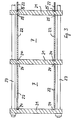
- the block molds 3 each consist of several rows of individual cheese molds 5 oriented parallel to the feed direction 4, which in the illustrated case each comprise four individual cheese molds 5.
- the frame 1 carries a feed hopper 6 for holding cheese curd, furthermore a plurality of metering cylinders 7, each with a metering piston 8 and an outlet funnel 9, the metering cylinders 7 with the metering pistons 8 and the outlet funnel 9 being combined to form one structural unit. Furthermore, the frame 1 is provided with two actuating rockers 10 for the metering pistons 8, each with an electric drive motor 11 and with four pneumatic or electric rotary motors 12 for opening and closing the metering cylinders 7.
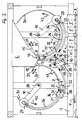
- the dosing cylinders 7 are arranged in pairs, the two dosing cylinders 7 of each pair extending in a vertical plane diverging from the lower end of the feed funnel 6 in a plane parallel to the feed direction 4 of the block molds 3 and each being curved in a circular arc and open at both ends, on the one hand via a formed by the mouth of the open end adjoining the feed hopper 6 13 communicate with the feed funnel 6 and, on the other hand, via an approximately half-length side outlet opening 14 with the outlet funnel 9 and with a cross slide 15 for closing the inlet opening 13, a swivel flap 16 for closing the outlet opening 14 and a whey spray head 17 in the region of the outlet opening 14 are provided.
- the inlet openings 13 of the two metering cylinders 7 each lie in one of two V-shaped planes.
- the pairs of diverging metering cylinders 7 are arranged side by side in a row which extends transversely to the transport path 2 and thus to the feed direction 4 of the block molds 3, the row comprising as many pairs of metering cylinders 7 as the number of rows of cheese molds 5 corresponds to the block molds 3 .
- the outlet funnel 9 extends past all V-shaped pairs of metering cylinders 7 between the metering cylinder 7 which runs on the left in FIG. 2 and the group on the right in FIG. 2 and is divided into several compartments 19 by transverse walls 18, each with a lower one Provided opening 20 and assigned to a pair of metering cylinders 7, which communicate with the associated compartment 19 via the two outlet openings 14.
- the block molds 3 are gradually passed in order to fill the four transverse rows of cheese molds 5 of each block mold 3 one after the other with curd from the feed funnel 6, whereby the same predetermined amount of curd comes into each cheese mold 5 of the respective transverse row through the associated lower opening 20 of the outlet funnel 9. Due to their arcuate curvature, the metering cylinders 7, despite their length, do not extend so far towards the transport path 2 that they could hinder the movement of the block molds 3, but rather run above the level of the lower openings 20 of the discharge funnel 9.
- the dosing cylinders 7 are each box-shaped and each have two ring-segment-shaped side walls 21 and two circular-arched side walls 22, all ring-segment-shaped side walls 21 being adjacent to both the group on the left in FIG. 2 and the group on the right in FIG. 2 dosing cylinders 7 which run opposite one another are clamped together by means of transverse anchors 23 and only one common annular side wall 21 is provided between each pair of dosing cylinders 7 of each group running side by side, which has two grooves 24 on both sides for receiving the adjacent longitudinal edges 25 of the two curved side walls 22 of one or the other dosing cylinder 7 is provided.
- each group of dosing cylinders 7 running side by side are each provided only on the inside with two such grooves 24, which receive the adjacent longitudinal edges 25 of the two curved side walls 22 of the dosing cylinder 7 delimited by the respective outer side wall 21.
- Each group of dosing cylinders 7 running next to one another is assigned an actuating rocker 10 for the simultaneous movement of all of its dosing pistons 8 and two rotary motors 12 for the simultaneous actuation of all of its cross slides 15 or swivel flaps 16.
- the metering pistons 8 of each group of metering cylinders 7 running side by side are each connected via a piston rod 26, which is curved in the shape of an arc of a circle, to a crossbar 27 of the associated actuating rocker 10, which is rotatably mounted on the frame 1 about an axis 28 which is concentric with the metering cylinders 7 and the respective piston rods 26 and with one Pinion 29 is provided which is driven by the electric motor 11 attached to the actuating rocker 10 and meshes with a toothed rack 30 which is coaxial with the axis of rotation 28 and which is provided on the frame 1.
- the cross slides 15 of each group of dosing cylinders 7 running side by side are attached to a cross bar 31 which is guided in the frame 1 in a transversely movable manner and can be pushed back and forth in the direction of the double arrow 32 by means of the rotary motor 12 assigned to the cross slides 15.
- the rotary motor 12 drives a pinion 33 which meshes with a toothed rack 34 which is arranged displaceably on the frame 1 and is connected to the crossbar 31.
- the swivel flaps 16 of each group of metering cylinders 7 running side by side are fastened on a common transverse shaft 35 which is rotatably mounted in the frame 1 and is connected to the associated rotary motor 12.
- the unit consisting of the metering cylinders 7 with the metering pistons 8 and the discharge funnel 9 is detachably fastened in the frame 1 and its piston rods 26, crossbars 31 and crossshafts 35 can be detached with the respective actuating rocker 10 or its crossbar 27 or with the respective rotary motor 12 connected in order to be able to replace the unit with a corresponding unit with differently dimensioned metering cylinders 7 if necessary.
- the metering pistons 8 can be removed for cleaning purposes from the respective metering cylinder 7 at its end facing away from the feed funnel 6 and releasably connected to the respective piston rod 26.
- each dosing cylinder 7 is provided at the end with an upper recess 36 and each dosing piston 8 on the piston rod side is provided with an open pocket 37 for receiving a ball head 38 at the adjacent end of the associated piston rod 26.
- a format plate 39 with several each adjoining a lower opening 20 of the discharge funnel 9 and leading to a cheese mold 5 of each transverse row of a block mold 3 leading under the discharge funnel 9 leading to a cheese curtain guide channels 40 is detachably fastened by means of resilient holders 41, in order if necessary against another Format plate 39 can be exchanged with other Käsebruchleitkanäle 40, for example one in which the Käsebruchleitkanäle 40 each connect two or more adjacent lower openings 20 of the discharge funnel 9 with a correspondingly large cheese mold 5, which is then fed by a corresponding number of metering cylinders 7 .
- the device works as follows. Empty block molds 3 are placed on the transport track 2 in order to be moved successively in the direction of arrow 4 towards the discharge funnel 9 and step by step past the lower openings 20 thereof, so that a transverse row of cheese molds 5 of the respective block mold 3 after the other under the Cheese curtain guide channels 40 of the format plate 39 arrive in order to be filled with cheese curd from the feed funnel 6 via the outlet funnel 9 by means of one or the other group of dosing cylinders 7 running alongside one another, the same predetermined quantity of cheese curd flowing to each cheese mold 5 of the respective transverse row.
- the feed hopper 6 becomes continuous or discontinuous charged with curd to always contain at least as much curd as is required to fill a group of dosing cylinders 7 running side by side.
- the first transverse row of cheese molds 5 of the first block mold 3 is to be filled on the transport path 2.
- the metering pistons 8 of the left-hand group in FIG. 2 group of metering cylinders 7 are located directly in front of the upper recesses 36 at the ends of the metering cylinders 7 facing away from the feed hopper 6, the inlet openings 13 of which are closed by the associated cross slide 15 and in which identical quantities of cheese curd are accommodated. which are located in front of the metering piston 8 below the outlet openings 14 of the metering cylinder 7.
- Their swing flaps 16 assume the open position and release the outlet openings 14.
- the whey spray heads 17 are switched on at a suitable time. After passing through the outlet openings 14, the metering pistons 8 continue to run in front of the cross slide 15, so that the metering cylinders 7 can be filled again.
Landscapes
- Life Sciences & Earth Sciences (AREA)
- Animal Husbandry (AREA)
- Environmental Sciences (AREA)
- Engineering & Computer Science (AREA)
- Mechanical Engineering (AREA)
- Dairy Products (AREA)
- Basic Packing Technique (AREA)
Claims (20)
Applications Claiming Priority (2)
| Application Number | Priority Date | Filing Date | Title |
|---|---|---|---|
| DE8812268U DE8812268U1 (de) | 1988-09-28 | 1988-09-28 | Vorrichtung zum dosierten Abfüllen von Käsebruch |
| DE8812268U | 1988-09-28 |
Publications (2)
| Publication Number | Publication Date |
|---|---|
| EP0361090A1 EP0361090A1 (fr) | 1990-04-04 |
| EP0361090B1 true EP0361090B1 (fr) | 1992-03-04 |
Family
ID=6828386
Family Applications (1)
| Application Number | Title | Priority Date | Filing Date |
|---|---|---|---|
| EP89115694A Expired - Lifetime EP0361090B1 (fr) | 1988-09-28 | 1989-08-25 | Dispositif pour remplir du caillé en quantités dosées |
Country Status (3)
| Country | Link |
|---|---|
| EP (1) | EP0361090B1 (fr) |
| DE (2) | DE8812268U1 (fr) |
| FR (1) | FR2636916B1 (fr) |
Families Citing this family (2)
| Publication number | Priority date | Publication date | Assignee | Title |
|---|---|---|---|---|
| GB9809123D0 (en) * | 1998-04-30 | 1998-07-01 | Elopak Systems | Method and apparatus |
| WO2024154125A1 (fr) * | 2023-01-17 | 2024-07-25 | Savoreat Ltd. | Unité d'alimentation en ingrédients de type pâte dans un robot culinaire |
Family Cites Families (4)
| Publication number | Priority date | Publication date | Assignee | Title |
|---|---|---|---|---|
| DE1966433B2 (de) * | 1969-03-07 | 1978-06-15 | Anton Steinecker Maschinenfabrik Gmbh, 8050 Freising | Vorrichtung zum Wenden eines Stapels von Käseformen |
| DE2230015A1 (de) * | 1971-07-09 | 1973-01-25 | Stefano Tomatis | Kaeseformmaschine |
| FR2290148A1 (fr) * | 1974-11-08 | 1976-06-04 | Findeling Charles | Machine a mouler des produits liquides ou pateux selon un dosage volumetrique |
| DE3637280C1 (en) * | 1986-11-03 | 1988-06-01 | Alpma Alpenland Maschb Hain & | Device for filling cheese curds into cheese moulds |
-
1988
- 1988-09-28 DE DE8812268U patent/DE8812268U1/de not_active Expired
- 1988-10-26 FR FR888813965A patent/FR2636916B1/fr not_active Expired - Lifetime
-
1989
- 1989-08-25 EP EP89115694A patent/EP0361090B1/fr not_active Expired - Lifetime
- 1989-08-25 DE DE8989115694T patent/DE58900916D1/de not_active Expired - Lifetime
Also Published As
| Publication number | Publication date |
|---|---|
| DE58900916D1 (de) | 1992-04-09 |
| EP0361090A1 (fr) | 1990-04-04 |
| DE8812268U1 (de) | 1988-12-08 |
| FR2636916A1 (fr) | 1990-03-30 |
| FR2636916B1 (fr) | 1992-07-24 |
Similar Documents
| Publication | Publication Date | Title |
|---|---|---|
| DE69501586T2 (de) | Abgabevorrichtung | |
| DE3543504C2 (fr) | ||
| DE3409263C2 (fr) | ||
| DE102007006133A1 (de) | Entleermagazin und Verfahren zum Entleeren von mit stabförmigen Produkten gefüllten Schachtschragen | |
| EP0099980B1 (fr) | Dispositif pour la formation de portions de tabac | |
| DE3316176A1 (de) | Vorrichtung zur bildung und zum abtransport von tabakportionen | |
| DE2835234A1 (de) | Vorrichtung und verfahren zum einstecken von stielen in giessformen | |
| DE69225617T2 (de) | Vorrichtung und Verfahren zur Freigabe von Artikeln | |
| EP0361090B1 (fr) | Dispositif pour remplir du caillé en quantités dosées | |
| DE69413003T2 (de) | Verfahren und Vorrichtung zum Wiegen von langgestreckten Teigwaren | |
| DE3630077C2 (fr) | ||
| DE1461845A1 (de) | Verfahren und Maschine zum Herstellen einer bestimmten Fuellguthoehe in einem Behaelter | |
| EP1424900B1 (fr) | Diviseuse pour pate | |
| DE69524240T2 (de) | Planier-sortiervorrichtung | |
| EP2108271A1 (fr) | Cartouche de vidage et procédé de vidage de combles de puits remplis de produits en forme de tiges | |
| EP2150138A2 (fr) | Magasin de vidage et dispositif de transfert pour dispositif de vidage de caissons, dispositif de vidage de caissons et procédé pour vider des caissons remplis de produits en forme de tige et acheminer ces produits jusqu'à des dispositifs en aval | |
| DE60002817T2 (de) | Vorrichtung zum Zuführen von Etiketten zu einer Etikettiermaschine | |
| DE1607092A1 (de) | Viehfuetterungsvorrichtung | |
| DE3637280C1 (en) | Device for filling cheese curds into cheese moulds | |
| DE4217585A1 (de) | Verfahren zur durchfuehrung des fuellens einer form mit einem steinmaterialgemisch zur realisierung einer platte aus diesem material und vorrichtung zur durchfuehrung des verfahrens | |
| EP3165472B1 (fr) | Groupe de dosage comprenant un réservoir de stockage | |
| DE1159341B (de) | Vorrichtung zum dosierten Abfuellen und gegebenenfalls zum Verpacken von gewichtsgenauen Einheiten plastischer Nahrungs- und Genussmittel | |
| EP4015174A1 (fr) | Dispositif de déchargement d'une matière de coulée coulante | |
| DE3814483C2 (de) | Vorrichtung zum Füllen von Verpackungsbehältern | |
| DE3019054C2 (de) | An einer Kunststoff-Spritzgießmaschine angeordnete Entnahmevorrichtung zum vereinzelten Entnehmen und Abgeben von Spritzlingen aus einer geöffneten Spritzgießform |
Legal Events
| Date | Code | Title | Description |
|---|---|---|---|
| PUAI | Public reference made under article 153(3) epc to a published international application that has entered the european phase |
Free format text: ORIGINAL CODE: 0009012 |
|
| AK | Designated contracting states |
Kind code of ref document: A1 Designated state(s): CH DE IT LI NL |
|
| 17P | Request for examination filed |
Effective date: 19900423 |
|
| 17Q | First examination report despatched |
Effective date: 19910816 |
|
| GRAA | (expected) grant |
Free format text: ORIGINAL CODE: 0009210 |
|
| AK | Designated contracting states |
Kind code of ref document: B1 Designated state(s): CH DE IT LI NL |
|
| REF | Corresponds to: |
Ref document number: 58900916 Country of ref document: DE Date of ref document: 19920409 |
|
| ITF | It: translation for a ep patent filed | ||
| PLBE | No opposition filed within time limit |
Free format text: ORIGINAL CODE: 0009261 |
|
| STAA | Information on the status of an ep patent application or granted ep patent |
Free format text: STATUS: NO OPPOSITION FILED WITHIN TIME LIMIT |
|
| 26N | No opposition filed | ||
| REG | Reference to a national code |
Ref country code: CH Ref legal event code: PUE Owner name: HUBERT BENTELE;HANSJOERG MAYER TRANSFER- HANSJOERG |
|
| PGFP | Annual fee paid to national office [announced via postgrant information from national office to epo] |
Ref country code: NL Payment date: 20030831 Year of fee payment: 15 |
|
| PGFP | Annual fee paid to national office [announced via postgrant information from national office to epo] |
Ref country code: CH Payment date: 20030916 Year of fee payment: 15 |
|
| REG | Reference to a national code |
Ref country code: CH Ref legal event code: PUE Owner name: DE KLOKSLAG AKTIVITEITEN BEHEER BV Free format text: HANSJOERG MAYER#SAENTISWEG 37#88239 WANGEN (DE) -TRANSFER TO- DE KLOKSLAG AKTIVITEITEN BEHEER BV#HICHTUMERWEG 7#8701 PG BOLSWARD (NL) Ref country code: CH Ref legal event code: NV Representative=s name: PATENTANWAELTE FELDMANN & PARTNER AG |
|
| NLS | Nl: assignments of ep-patents |
Owner name: DE KLOKSLAG AKTIVITEITEN BEHEER B.V. |
|
| PG25 | Lapsed in a contracting state [announced via postgrant information from national office to epo] |
Ref country code: LI Free format text: LAPSE BECAUSE OF NON-PAYMENT OF DUE FEES Effective date: 20040831 Ref country code: CH Free format text: LAPSE BECAUSE OF NON-PAYMENT OF DUE FEES Effective date: 20040831 |
|
| PG25 | Lapsed in a contracting state [announced via postgrant information from national office to epo] |
Ref country code: NL Free format text: LAPSE BECAUSE OF NON-PAYMENT OF DUE FEES Effective date: 20050301 |
|
| REG | Reference to a national code |
Ref country code: CH Ref legal event code: PL |
|
| NLV4 | Nl: lapsed or anulled due to non-payment of the annual fee |
Effective date: 20050301 |
|
| PGFP | Annual fee paid to national office [announced via postgrant information from national office to epo] |
Ref country code: DE Payment date: 20060720 Year of fee payment: 18 |
|
| PGFP | Annual fee paid to national office [announced via postgrant information from national office to epo] |
Ref country code: IT Payment date: 20060831 Year of fee payment: 18 |
|
| PG25 | Lapsed in a contracting state [announced via postgrant information from national office to epo] |
Ref country code: DE Free format text: LAPSE BECAUSE OF NON-PAYMENT OF DUE FEES Effective date: 20080301 |
|
| PG25 | Lapsed in a contracting state [announced via postgrant information from national office to epo] |
Ref country code: IT Free format text: LAPSE BECAUSE OF NON-PAYMENT OF DUE FEES Effective date: 20070825 |