EP0361108A1 - Dispositif destiné au mélange par vibrations d'une capsule à plusieurs constituants, plus spécialement pour l'art dentaire - Google Patents
Dispositif destiné au mélange par vibrations d'une capsule à plusieurs constituants, plus spécialement pour l'art dentaire Download PDFInfo
- Publication number
- EP0361108A1 EP0361108A1 EP19890115831 EP89115831A EP0361108A1 EP 0361108 A1 EP0361108 A1 EP 0361108A1 EP 19890115831 EP19890115831 EP 19890115831 EP 89115831 A EP89115831 A EP 89115831A EP 0361108 A1 EP0361108 A1 EP 0361108A1
- Authority
- EP
- European Patent Office
- Prior art keywords
- capsule
- mixing
- arrangement according
- guide
- chamber
- Prior art date
- Legal status (The legal status is an assumption and is not a legal conclusion. Google has not performed a legal analysis and makes no representation as to the accuracy of the status listed.)
- Granted
Links
- 239000002775 capsule Substances 0.000 title claims abstract description 103
- 238000002156 mixing Methods 0.000 title claims abstract description 65
- 239000007788 liquid Substances 0.000 claims abstract description 13
- 230000004913 activation Effects 0.000 claims description 11
- 210000000078 claw Anatomy 0.000 claims description 10
- 230000009172 bursting Effects 0.000 claims description 5
- 238000003805 vibration mixing Methods 0.000 claims description 5
- 239000011888 foil Substances 0.000 abstract description 8
- 230000003213 activating effect Effects 0.000 abstract description 3
- 230000010355 oscillation Effects 0.000 description 6
- 230000001133 acceleration Effects 0.000 description 3
- 238000006073 displacement reaction Methods 0.000 description 3
- 238000005192 partition Methods 0.000 description 3
- 230000005540 biological transmission Effects 0.000 description 2
- 238000010586 diagram Methods 0.000 description 2
- 238000004519 manufacturing process Methods 0.000 description 2
- 238000000034 method Methods 0.000 description 2
- 238000009527 percussion Methods 0.000 description 2
- 239000004743 Polypropylene Substances 0.000 description 1
- 229910052782 aluminium Inorganic materials 0.000 description 1
- XAGFODPZIPBFFR-UHFFFAOYSA-N aluminium Chemical compound [Al] XAGFODPZIPBFFR-UHFFFAOYSA-N 0.000 description 1
- 230000009969 flowable effect Effects 0.000 description 1
- 239000000463 material Substances 0.000 description 1
- 239000012528 membrane Substances 0.000 description 1
- 229910052751 metal Inorganic materials 0.000 description 1
- 239000002184 metal Substances 0.000 description 1
- 239000000203 mixture Substances 0.000 description 1
- -1 polypropylene Polymers 0.000 description 1
- 229920001155 polypropylene Polymers 0.000 description 1
- 239000007787 solid Substances 0.000 description 1
- 230000003068 static effect Effects 0.000 description 1
Images
Classifications
-
- B—PERFORMING OPERATIONS; TRANSPORTING
- B65—CONVEYING; PACKING; STORING; HANDLING THIN OR FILAMENTARY MATERIAL
- B65D—CONTAINERS FOR STORAGE OR TRANSPORT OF ARTICLES OR MATERIALS, e.g. BAGS, BARRELS, BOTTLES, BOXES, CANS, CARTONS, CRATES, DRUMS, JARS, TANKS, HOPPERS, FORWARDING CONTAINERS; ACCESSORIES, CLOSURES, OR FITTINGS THEREFOR; PACKAGING ELEMENTS; PACKAGES
- B65D81/00—Containers, packaging elements, or packages, for contents presenting particular transport or storage problems, or adapted to be used for non-packaging purposes after removal of contents
- B65D81/32—Containers, packaging elements, or packages, for contents presenting particular transport or storage problems, or adapted to be used for non-packaging purposes after removal of contents for packaging two or more different materials which must be maintained separate prior to use in admixture
- B65D81/3255—Containers provided with a piston or a movable bottom, and permitting admixture within the container
-
- A—HUMAN NECESSITIES
- A61—MEDICAL OR VETERINARY SCIENCE; HYGIENE
- A61C—DENTISTRY; APPARATUS OR METHODS FOR ORAL OR DENTAL HYGIENE
- A61C5/00—Filling or capping teeth
- A61C5/60—Devices specially adapted for pressing or mixing capping or filling materials, e.g. amalgam presses
- A61C5/62—Applicators, e.g. syringes or guns
- A61C5/64—Applicators, e.g. syringes or guns for multi-component compositions
-
- A—HUMAN NECESSITIES
- A61—MEDICAL OR VETERINARY SCIENCE; HYGIENE
- A61C—DENTISTRY; APPARATUS OR METHODS FOR ORAL OR DENTAL HYGIENE
- A61C5/00—Filling or capping teeth
- A61C5/60—Devices specially adapted for pressing or mixing capping or filling materials, e.g. amalgam presses
- A61C5/66—Capsules for filling material
-
- B—PERFORMING OPERATIONS; TRANSPORTING
- B01—PHYSICAL OR CHEMICAL PROCESSES OR APPARATUS IN GENERAL
- B01F—MIXING, e.g. DISSOLVING, EMULSIFYING OR DISPERSING
- B01F31/00—Mixers with shaking, oscillating, or vibrating mechanisms
- B01F31/20—Mixing the contents of independent containers, e.g. test tubes
- B01F31/23—Mixing the contents of independent containers, e.g. test tubes by pivoting the containers about an axis
-
- B—PERFORMING OPERATIONS; TRANSPORTING
- B01—PHYSICAL OR CHEMICAL PROCESSES OR APPARATUS IN GENERAL
- B01F—MIXING, e.g. DISSOLVING, EMULSIFYING OR DISPERSING
- B01F33/00—Other mixers; Mixing plants; Combinations of mixers
- B01F33/25—Mixers with loose mixing elements, e.g. loose balls in a receptacle
-
- B—PERFORMING OPERATIONS; TRANSPORTING
- B01—PHYSICAL OR CHEMICAL PROCESSES OR APPARATUS IN GENERAL
- B01F—MIXING, e.g. DISSOLVING, EMULSIFYING OR DISPERSING
- B01F33/00—Other mixers; Mixing plants; Combinations of mixers
- B01F33/50—Movable or transportable mixing devices or plants
- B01F33/501—Movable mixing devices, i.e. readily shifted or displaced from one place to another, e.g. portable during use
- B01F33/5011—Movable mixing devices, i.e. readily shifted or displaced from one place to another, e.g. portable during use portable during use, e.g. hand-held
-
- B—PERFORMING OPERATIONS; TRANSPORTING
- B01—PHYSICAL OR CHEMICAL PROCESSES OR APPARATUS IN GENERAL
- B01F—MIXING, e.g. DISSOLVING, EMULSIFYING OR DISPERSING
- B01F35/00—Accessories for mixers; Auxiliary operations or auxiliary devices; Parts or details of general application
- B01F35/71—Feed mechanisms
- B01F35/713—Feed mechanisms comprising breaking packages or parts thereof, e.g. piercing or opening sealing elements between compartments or cartridges
- B01F35/7131—Breaking or perforating packages, containers or vials
-
- Y—GENERAL TAGGING OF NEW TECHNOLOGICAL DEVELOPMENTS; GENERAL TAGGING OF CROSS-SECTIONAL TECHNOLOGIES SPANNING OVER SEVERAL SECTIONS OF THE IPC; TECHNICAL SUBJECTS COVERED BY FORMER USPC CROSS-REFERENCE ART COLLECTIONS [XRACs] AND DIGESTS
- Y10—TECHNICAL SUBJECTS COVERED BY FORMER USPC
- Y10S—TECHNICAL SUBJECTS COVERED BY FORMER USPC CROSS-REFERENCE ART COLLECTIONS [XRACs] AND DIGESTS
- Y10S366/00—Agitating
- Y10S366/602—Amalgam mixer, e.g. dental filling
Definitions
- the invention relates to an arrangement for treating a multi-component mixing capsule, in particular for dental purposes, by means of a vibration mixing device, in which the mixing capsule comprises a mixing chamber and a chamber separated therefrom by a burst closure for receiving a liquid component, which consists of a solid component forming the mixing chamber Container part connected first wall and a second wall is limited, which is approachable to open the burst closure and to displace the liquid component from the chamber of the first wall under the action of an activation force.
- the elongated mixing space is separated from the chamber by a perforated wall through which the chamber on one side is limited. On the other hand, it is delimited by an overflow cover which can be telescoped against the capsule part forming the mixing chamber or by a piston.
- an overflow cover which can be telescoped against the capsule part forming the mixing chamber or by a piston.
- the film bag lies against the movable chamber wall with a surface whose size is a multiple of the opening cross-sectional area.
- the forces to be exerted on the movable wall are therefore considerable and amount to several decanewtons. It has been considered to reduce this effort by using switchable valve members between the chamber and the mixing space (US-PS 25 27 991). However, these have not been able to be put into practice because sufficiently precise valve elements cannot be economically produced under the conditions of mass production.
- Mixing capsules for dental purposes are also known (DE-PS 28 31 005), which are activated without a special activation action solely by the mixing movement, by destroying and emptying a foil pouch contained within the mixing space by the inertial forces effective in the mixing vibration.
- this principle cannot easily be applied to specifically light liquids.
- this type of capsule cannot be used as an application syringe (DE-PS 19 39 316), because the bag remnants contained in the mixing space hinder the emptying of the mixing space through a nozzle opening.
- a dental capsule is known (DE-OS 29 31 262), in which the liquid component is kept ent in the chamber without a surrounding foil bag, the partition between the mixing chamber and the chamber being displaceable under the impact force of a pestle contained in the mixing chamber in such a way that valve openings opened between the chamber and the mixing chamber and the liquid is displaced from the chamber through these openings into the mixing chamber.
- the capsule has the disadvantage that it is expensive to manufacture because the fit of the ver sliding wall in the capsule must meet high tightness requirements.
- This capsule cannot be made in the form of an application syringe either, because the pestle in the mixing chamber prevents the contents of the mixing chamber from being completely emptied by means of a piston.
- the object of the invention is therefore to make it easier to handle the dental capsule specified at the outset, which presupposes the presence of a burst closure, in particular a foil pouch containing the liquid component.
- the capsule should be suitable for different forms of application, including the design as an application syringe.
- the solution according to the invention is that on the side of the chamber facing away from the mixing chamber, a guide is provided which runs approximately in the direction of the vibration of the mixing device, in which the second wall of the chamber is movable with it and is associated with it by the guide cooperating end face of a first impact body and that a second impact body is connected to the part of the capsule forming the mixing chamber, one of the two bodies being connected to the vibratory drive of the vibration mixing device and the other being movable relative to the latter by means of the guide.
- the invention comprises two steps.
- the first consists in the application of the percussion body known per se to the opening of the burst closure.
- the second concerns the structural design.
- the first step is surprising insofar as - as described above, high forces are required to cause a film bag to burst.
- high forces are required to cause a film bag to burst.
- This would require such a large impact body mass that the burst pressure of the foil bag can be exceeded with a single impact.
- Such a mass would be so large that it cannot be accommodated in the limited area of a mixing capsule and cannot be moved by the limited driving forces of commercially available vibration mixing devices.
- it has surprisingly been found that such a size of the mass is not necessary. Even if the force of the single blow is much less than that static force that causes the bag to burst can be achieved by repeated, rapid repetition of the bag opening.
- the second step consists in the constructive execution, namely in the arrangement of an impact body outside the mixing area exclusively for the purpose of activating the capsule. This keeps the mixing chamber free of foreign objects and can be used as the ejection cylinder of an application capsule.
- a burst seal is primarily to be understood as a film bag which is caused to burst in the region of an opening of the wall separating the mixing space and the chamber, in the following we will only speak of a film bag.
- the bursting closure are also conceivable, for example in the form of a bursting film sealed over the opening or a membrane which is formed in one piece with the wall and which can contain predetermined breaking lines. The liquid component is then freely contained in the chamber, the second chamber wall being tightly sealed.
- the capsule is freely movable in the guide and the first impact body is connected to the oscillating drive, the guide and at least part of the first impact body expediently being formed by a guide container receiving the capsule, which preferably as such is inserted into the Vibration mixer can be clamped or forms part of the vibration mixer.
- the second impact body can be formed by the capsule part forming the mixing space or can be firmly connected to it. The capsule is tossed back and forth in the guide container between its ends, the second, movable wall of the chamber bouncing against the end wall of the guide container opposite it, which on the Activating force acting on the chamber is determined by the speed difference and the smaller of the impact body masses involved.
- the guide is formed by a capsule receptacle connected to a vibratory drive, in which the first impact body is freely movable in the direction of vibration, the second impact body being formed by the capsule receptacle.
- the capsule part forming the mixing space can be firmly connected to the capsule receptacle, with only the first impact body moving in the free space adjacent to the movable chamber wall.
- the capsule can also be movable in the direction of vibration in the capsule receptacle, so that both the capsule and the first percussion body move freely in the capsule receptacle.
- the activation forces are then exerted by the striking body on the movable chamber wall when the end of the capsule facing away from the first striking body rests against the end face of the capsule receptacle and the first striking body strikes the movable chamber wall.
- the capsule is firmly connected to the second impact body by abutment, so that it can be supported on it during the impact of the first impact body. It is irrelevant whether there are also collisions between the first impact body and the capsule if the capsule is not supported.
- the guide can be arranged fixedly on the capsule, the first striking body being movable therein, while the second striking body is formed by the capsule part forming the mixing space and, if appropriate, by parts of the oscillating drive firmly connected to it.
- the fixed connection of the guide to the capsule can be designed such that the guide constantly forms part of the capsule and thus the capsule as such already contains all the elements that enable automatic activation.
- the advantage of this design is that the capsule is clamped into the vibration mixer without any further measures and the activation and mixing takes place without any action. Instead, it is also possible to connect the reusable guide with the impact body to the capsule designed as a disposable item only when the activation and mixing are to take place.
- an impact body which can move freely in a guide an impact body which is connected to the capsule and is preferably held in constant contact with the movable wall or on the film bag can also be used.
- the guidance of the impact body or the impact body itself is expediently designed as a piston, by means of which the feed force is achieved by means of an application device can be exerted on the application piston delimiting the mixing chamber. If there is talk in the context of the invention that the wall separating the mixing chamber from the chamber is firmly connected to the capsule part forming the mixing chamber, it should not be ruled out that this wall, for example as part of such an application piston, has other functional contexts is movable relative to the capsule part forming the mixing space.
- the advantage of a freely movable impact body is that larger speed differences can occur between the impact body and the associated capsule part, because the capsule part may have already reversed movement under the influence of the oscillating drive while the impact body is still moving in the previous direction.
- the free movement distance of the impact body in the guide part receiving it should be at least about one tenth of the oscillation drive amplitude.
- the mass of the first impact body can generally be less than 10 grams, preferably even less than 5 grams.
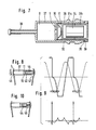
- Fig. 1 you can see an elongated, consisting of container part 1 and lid 2 container, which is clamped between the claws 3 of a commercially available vibration mixer.
- the claws 3 are seated on arms 4 which are stretched towards one another in order to be able to securely grip the ends of the elongated container 1, 2.
- the vibration takes place at a frequency of at least 2,500 rpm, preferably about 3,000 rpm approximately in the direction of arrow 5, i.e. approximately in the longitudinal direction of the container 1, 2.
- the container 1, 2 forms an elongated, cylindrical cavity for receiving and guiding the capsule 6.
- This forms a mixing space 8 within a part 7, which is separated by a perforated wall 9 from a foil bag 10 containing the liquid component, which is in a chamber 11 is included, which is formed between the perforated wall 9 and a cover lid 12 which can be telescopically pushed onto the capsule part 7, being held in its respective position by friction.
- the capsule 6 is elongated, as is known from commercially available dental capsules, slightly in diameter compared to the cylindrical interior of the container 1, so that it can slide easily in the longitudinal direction.
- the capsule 6 Under the mixed vibration, the capsule 6 is thrown back and forth between the end walls, which delimit the interior of the container 1, 2, impact forces acting on the cover 12 when it stops on the right end wall in the drawing, which depend on the speed difference and on the Depend on the size of the masses involved.
- the speed difference is determined by the frequency of the vibratory drive and the relationship of the free travel of the capsule 6 in the interior of the container 1, 2 to the oscillation amplitude of this container.
- the free movement distance of the capsule in the container should be smaller than the oscillation amplitude of the container and is preferably smaller than half the oscillation amplitude, preferably in the range between one twentieth and one third of this amplitude. This also applies to other embodiments.
- the masses involved are formed on the one hand by the cover 2 and the parts firmly connected to it at the moment of impact, namely the claw 3 and part of the associated arm 4.
- the container 1 can also be counted as one of these masses if it is firmly attached to the container 2 is connected.
- These parts together form the first impact body.
- the second striking body is formed by those parts which are firmly connected to the perforated wall 9, that is to say by the capsule part 7 forming the mixing space 8.
- the decisive factor is the lower of the two striking body masses, in this example, as a rule, the mass of the capsule part 7. They should be at least about 3 grams if an oscillation frequency of 3000 min ⁇ 1 can be assumed.
- the lid 12 of the capsule strikes against the lid 2 of the container 1, 2 until the foil bag 10 bursts and its contents pour into the mixing space 8 through the perforated wall 9 until the liquid component is completely displaced from the chamber 11 .
- Capsule 6 and container 1, 2 can be marketed as an easy-to-use unit. Instead, it is also possible to treat only the capsule 6 as a disposable unit, while the outer container 1, 2 is used several times.
- the shape of the container can be modified many times and can even lose its container character without losing its functionality. While the execution according to FIG. 1 assumes that the container 1, 2 is a separate part to be clamped into the claws 3 of the mixing device, the variant according to FIGS. 2 and 3 demonstrates the possibility of forming it as part of the mixing device by being firmly connected to a swing arm 24 , which takes the place of the swing arms 4.
- the container consists of a first part 21 which is rigidly connected to the swing arm 24 and a cover part 22 which can be detached from the part 21 for inserting and removing the capsule 6 and which can be held in the closed position by spring force, a snap lock or the like.
- the guide need not be designed like a container, as the embodiment variant according to FIG. 5 shows.
- the capsule 6 is held by a clamp 25 which is attached to an arm 26 which is articulated at 27 in the mixer. Terminal 25 and arm 26 are low-mass.
- the capsule is guided through it in its longitudinal direction along an arc around the joint 27.
- the arm 26 could also be resilient.
- stop plates 28 In the guide path of the capsule 6 there are stop plates 28, the spacing from one another of which is somewhat greater than the length of the capsule 6. They are fastened to oscillating arms 29 which oscillate essentially in synchronism and which alternately meet the ends of the capsule 6 and these between them throw.
- the function is the same as that of the embodiments according to FIGS. 1 to 3, the first impact body being formed by the right stop plate and the second impact body being formed by the part of the capsule forming the mixing space.
- the second embodiment according to FIG. 5 differs from that according to FIG. 1 in that, in addition to the capsule 6 in the space of the container 1, 2, on the side of the capsule cover 12 there is a striking body 13 made of specifically heavy material such as metal, for example spherical has and the diameter is a little less than the inner diameter of the outer capsule body 1.
- the common length of the capsule 6 and the striking body 13 is less than the length of the interior of the container 1, 2nd
- the impact takes place between the ball 13 as the first striking body and the cover 12 of the capsule 6.
- the capsule is lighter than the striking body 13, so that it is pushed against the left end wall of the container 1, 2 and supported there . Therefore, the first impact body is formed by the ball 13 and the second impact body by the common masses of the capsule part 7, the container 1 and the left claw 3. Otherwise, the function is the same as in the case of the first embodiment.
- the chamber 11 is formed on the one hand by the perforated wall 9 and on the other hand by the end wall of a hollow piston 31 which is guided in a rear extension 32 of the container part 37 with weak friction.
- an impact body 34 In the cavity 33 of the hollow piston 31 there is an impact body 34, the length of which is slightly less than the free length of the space 33. With every second reversal of movement, the impact body 34 strikes the end wall of the hollow piston 31 on the chamber side and presses it against the film bag 10 to let it burst and empty it.
- the function is the same as that of the first embodiment. So that the hollow piston 31 remains in contact with the film bag 10 as continuously as possible, it is expediently provided that it is pushed to the left by a resilient force in the drawing. This can - as indicated in the drawing - be generated in that the hollow piston 31 protrudes beyond the rear end 35 of the wall 32 so that it is acted upon by the clamping force of the claw 3.
- FIG. 7 A preferred embodiment of the third embodiment is shown in detail in FIG. 7 in longitudinal section on an enlarged scale.
- the capsule part 37 can be seen therein, which carries an application nozzle 38 at the front end.
- the perforated wall 9 is designed as the end wall of a piston 36, the rear edge 39 of which extends outward beyond the rear edge 35 of the rear wall part 32 of the container part 37.
- the hollow piston 31, which is composed of a front half 31a and a rear half 31b, which are not connected to one another and are held together only by a weak frictional engagement within the piston 36, is located behind the film bag 10 within the piston 36. They take up the impact body 34, which is approximately 3 mm shorter than the space in the hollow piston 31 that receives it.
- the striking body 34 When the capsule is clamped in a mixing device and is exposed to the mixing vibration, the striking body 34 alternately strikes the front and rear end walls of the hollow piston 31. When striking the front end wall delimiting the chamber 11, it pushes the front hollow piston part 31a against the film bag 10 and generates therein a pressure which, after repeated opening, finally leads to the latter bursting in the region of the opening in the perforated wall 9. In the event of further impacts, it pushes the front hollow piston part 31a against the perforated wall 9 until the flowable component is completely displaced out of the film bag 10 into the mixing space 8. Since the front part 31a of the hollow piston is independent of the rear part 31b, its advancement is not hindered thereby that the striking body 34 tends to push the rear hollow piston part 31b in the drawing to the right or against a stop, not shown.
- the perforated wall 9 is secured against the forces acting on it by the rear edge 39 of the piston 36 abutting the rear edge 35 of the container part 37 and, in this respect, firmly connected to the capsule part 37.
- the hollow piston 31 is advanced, as a result of which the rear, projecting edge 39 of the piston 36 loses its internal support and therefore no longer opposes the advancement of the piston 36.
- FIG. 7 The embodiment according to FIG. 7 has proven itself with the following dimensions: Impact weight: 3 g Stroke stroke at the start of vibration: 3 mm Stroke at the end of activation: 5 mm Start of activation at 2,400 min ⁇ 1: 4 - 5 sec. Start of activation at 3,000 - 3,500 min ⁇ 1: approx. 3 sec. Bag film: soft aluminum 0.015 mm, laminated with 15 g / m2 polypropylene Diameter of the hole in the perforated wall: 3 mm
- the fourth embodiment according to FIG. 8 differs from that according to FIG. 6 in that the striking body 44 is not freely movable in the capsule.
- the activation force is generated in that the capsule as a whole is exposed to a high, as sudden as possible movement by rapid reversal of movement.
- a stop 45 is shown to the left of the claw 3, against which the claw 3 strikes at the end of each oscillation process, so that the speed of the capsule is braked suddenly and a high acceleration is exerted as a result.
- the impact body 44 which in this embodiment also forms one of the walls delimiting the chamber 11, in constant contact with the film bag, which is done in the embodiment according to FIG. 8 in that the right claw 3 engages the striking body 44 projecting beyond the end 47 of the container wall 42.
- a spring 46 is provided within the capsule for this purpose.
- Fig. 9 shows the path in the upper part with a thin line and the speed of the capsule with a double line.
- the path is cut off at one end of the vibration by the stop 45, so that the speed abruptly goes to zero at this point (or even in the opposite direction in the case of elastic impact). Accordingly, the acceleration diagram shown below has a high peak at this point.
Landscapes
- Health & Medical Sciences (AREA)
- Chemical Kinetics & Catalysis (AREA)
- Chemical & Material Sciences (AREA)
- Life Sciences & Earth Sciences (AREA)
- Oral & Maxillofacial Surgery (AREA)
- Dentistry (AREA)
- Epidemiology (AREA)
- Animal Behavior & Ethology (AREA)
- General Health & Medical Sciences (AREA)
- Public Health (AREA)
- Veterinary Medicine (AREA)
- Mechanical Engineering (AREA)
- Engineering & Computer Science (AREA)
- Dental Tools And Instruments Or Auxiliary Dental Instruments (AREA)
- Package Specialized In Special Use (AREA)
- Locating Faults (AREA)
Applications Claiming Priority (2)
| Application Number | Priority Date | Filing Date | Title |
|---|---|---|---|
| DE3832757A DE3832757C2 (de) | 1988-09-27 | 1988-09-27 | Anordnung zum Behandeln einer Mehrkomponentenmischkapsel, insbesondere für Dentalzwecke, mittels eines Vibrationsmischgeräts |
| DE3832757 | 1988-09-27 |
Publications (2)
| Publication Number | Publication Date |
|---|---|
| EP0361108A1 true EP0361108A1 (fr) | 1990-04-04 |
| EP0361108B1 EP0361108B1 (fr) | 1992-03-11 |
Family
ID=6363801
Family Applications (1)
| Application Number | Title | Priority Date | Filing Date |
|---|---|---|---|
| EP89115831A Expired - Lifetime EP0361108B1 (fr) | 1988-09-27 | 1989-08-28 | Dispositif destiné au mélange par vibrations d'une capsule à plusieurs constituants, plus spécialement pour l'art dentaire |
Country Status (7)
| Country | Link |
|---|---|
| US (1) | US5088830A (fr) |
| EP (1) | EP0361108B1 (fr) |
| JP (1) | JPH02116364A (fr) |
| AU (1) | AU618844B2 (fr) |
| CA (1) | CA1313187C (fr) |
| DE (2) | DE3832757C2 (fr) |
| NZ (1) | NZ230601A (fr) |
Cited By (1)
| Publication number | Priority date | Publication date | Assignee | Title |
|---|---|---|---|---|
| GB2259901B (en) * | 1991-09-30 | 1995-08-16 | Centrix Inc | Cement mixing capsule |
Families Citing this family (24)
| Publication number | Priority date | Publication date | Assignee | Title |
|---|---|---|---|---|
| DE9204508U1 (de) * | 1992-04-02 | 1993-08-05 | Ihde, Stefan, Prof.Dr., Uetliburg | Mischkapsel, insbesondere für Dentalzwecke |
| DE9206892U1 (de) * | 1992-05-21 | 1992-12-03 | Ihde, Stefan, Prof.Dr., Uetliburg | Mehrkomponenten-Mischkapsel mit Ausspritzeinrichtung für die angemischte Masse, insbesondere für Dentalzwecke |
| US5509530A (en) * | 1995-07-20 | 1996-04-23 | Wykle Research, Inc. | Compartmentalized dental amalgam mixing capsule |
| DE29821193U1 (de) * | 1998-11-26 | 2000-03-30 | ESPE Dental AG, 82229 Seefeld | Mischkapsel |
| US6491422B1 (en) | 2000-05-16 | 2002-12-10 | Rütten Engineering | Mixer |
| DE10057616B4 (de) | 2000-11-21 | 2006-09-14 | Stryker Trauma Gmbh | Verfahren zum Mischen und Applizieren von fließfähigem Knochenzement sowie Mischvorrichtung für Knochenzement |
| US6494611B2 (en) * | 2001-01-26 | 2002-12-17 | Howmedica Osteonics Corp. | Apparatus for mixing a liquid and dry powdered components |
| RU2201341C1 (ru) * | 2001-08-02 | 2003-03-27 | Открытое акционерное общество Московский институт материаловедения и эффективных технологий | Смеситель-капсулятор |
| US6981794B2 (en) * | 2002-04-12 | 2006-01-03 | Hynetics Llc | Methods for mixing solutions |
| US6908223B2 (en) | 2002-04-12 | 2005-06-21 | Hynetics Llc | Systems for mixing liquid solutions and methods of manufacture |
| US6923567B2 (en) * | 2002-04-12 | 2005-08-02 | Hynetics Llc | Mixing tank assembly |
| WO2004082506A1 (fr) * | 2003-03-21 | 2004-09-30 | Alfred Schmid Ag Gossau | Capsule de melange |
| RU2248953C1 (ru) * | 2003-09-02 | 2005-03-27 | Закрытое акционерное общество "ИМЭТСТРОЙ" (ЗАО "ИМЭТСТРОЙ") | Способ изготовления крупнопористого бетона на плотных заполнителях |
| DK2467100T3 (en) * | 2009-08-20 | 2016-02-15 | Tecres Spa | BONE CEMENT MIXER |
| AU2014201994B2 (en) * | 2013-04-12 | 2018-08-30 | Sdi Limited | A dental capsule |
| AU2014201991B2 (en) * | 2013-04-12 | 2019-05-02 | Sdi Limited | A dental capsule |
| JP6581109B2 (ja) * | 2014-04-16 | 2019-09-25 | スリーエム イノベイティブ プロパティズ カンパニー | 歯科材料を混合及び分注するためのカプセル |
| US10792228B2 (en) | 2015-11-11 | 2020-10-06 | 3M Innovative Properties Company | Kit of parts for producing a glass ionomer cement, process of production and use thereof |
| US11135138B2 (en) | 2017-02-13 | 2021-10-05 | 3M Innovative Properties Company | Self-adhesive dental resin composition and use thereof |
| DE102017111725B4 (de) * | 2017-05-30 | 2024-02-08 | Kulzer Gmbh | Zwei Komponenten Mischkapsel, insbesondere für dentale Zwecke |
| EP4032498A1 (fr) * | 2021-01-21 | 2022-07-27 | Septodont ou Septodont SAS ou Specialites Septodont | Appareil pour activer une cartouche comprenant un matériau à composants multiples et/ou pour mélanger par vibration de ladite cartouche |
| HRP20251349T1 (hr) * | 2021-03-16 | 2025-12-19 | Swissmeca Sa | Epruveta za uzorak i postupak za raspršivanje i homogenizaciju |
| WO2024003631A1 (fr) | 2022-06-28 | 2024-01-04 | 3M Innovative Properties Company | Kit de partie pour la production de ciment ionomère de verre à haute résistance à la compression |
| CN120282834A (zh) * | 2022-12-01 | 2025-07-08 | 国立大学法人茨城大学 | 搅拌器及搅拌方法 |
Family Cites Families (14)
| Publication number | Priority date | Publication date | Assignee | Title |
|---|---|---|---|---|
| US2527991A (en) * | 1947-11-21 | 1950-10-31 | Alvin A Greenberg | Container |
| US2487236A (en) * | 1947-12-31 | 1949-11-08 | Alvin A Greenberg | Compartmented container having a rupturable partition |
| DE1287251B (de) * | 1964-09-02 | 1969-01-16 | Dentaire Ivoclar Ets | Mehrkammeriger Behaelter fuer die Aufnahme von miteinander reagierenden Substanzen fuer die Herstellung von gebrauchsfertigen Dentalpraeparaten |
| DE2400970C2 (de) * | 1969-08-01 | 1975-11-06 | Etablissement Dentaire Ivoclar, Schaan (Liechtenstein) | Mischbehälter für die Aufnahme von miteinander reagierenden Substanzen für die Herstellung von gebrauchsfertigen Dentalpräparaten |
| US3638918A (en) * | 1970-03-09 | 1972-02-01 | Dental Design Systems | Mixing of substances |
| JPS4856894U (fr) * | 1971-10-29 | 1973-07-20 | ||
| CA1067729A (fr) * | 1976-11-03 | 1979-12-11 | Weatherford Oil Tool Co. | Porte-capsule pour amalgame dentaire |
| CA1073009A (fr) * | 1977-03-18 | 1980-03-04 | Weatherford Oil Tool Co. | Appareil pour preparer les amalgames dentaires |
| US4182447A (en) * | 1977-07-27 | 1980-01-08 | Ira Kay | Device for storing, transporting and mixing reactive ingredients |
| IL52695A (en) * | 1977-08-10 | 1979-11-30 | Silmet Ltd | Mixing capsule |
| SE444639B (sv) * | 1978-08-02 | 1986-04-28 | Johnson & Johnson | Engangskapsel for dentalamalgam |
| SE440852B (sv) * | 1984-10-02 | 1985-08-26 | Peter Johan Torsten Tornqvist | Anordning for att mekaniskt sla sonder en barrier mellan blandbara ingredienser och blanda dessa |
| DE8809184U1 (de) * | 1988-07-18 | 1988-09-08 | Mühlbauer, Ernst, 2000 Hamburg | Mehrkomponenten-Mischkapsel mit Ausspritzeinrichtung für die gemischte Masse, insbesondere für Dentalzw ecke |
| US4871261A (en) * | 1988-09-29 | 1989-10-03 | Minnesota Mining And Manufacturing Company | Vacuum mixing apparatus for dental materials |
-
1988
- 1988-09-27 DE DE3832757A patent/DE3832757C2/de not_active Expired - Fee Related
-
1989
- 1989-08-28 DE DE8989115831T patent/DE58900950D1/de not_active Expired - Lifetime
- 1989-08-28 EP EP89115831A patent/EP0361108B1/fr not_active Expired - Lifetime
- 1989-09-05 US US07/402,826 patent/US5088830A/en not_active Expired - Fee Related
- 1989-09-07 CA CA000610558A patent/CA1313187C/fr not_active Expired - Fee Related
- 1989-09-08 NZ NZ230601A patent/NZ230601A/en unknown
- 1989-09-20 JP JP1246243A patent/JPH02116364A/ja active Pending
- 1989-09-25 AU AU41746/89A patent/AU618844B2/en not_active Ceased
Non-Patent Citations (1)
| Title |
|---|
| Keine Entgegenhaltungen. * |
Cited By (1)
| Publication number | Priority date | Publication date | Assignee | Title |
|---|---|---|---|---|
| GB2259901B (en) * | 1991-09-30 | 1995-08-16 | Centrix Inc | Cement mixing capsule |
Also Published As
| Publication number | Publication date |
|---|---|
| DE3832757C2 (de) | 1997-08-07 |
| US5088830A (en) | 1992-02-18 |
| NZ230601A (en) | 1992-02-25 |
| JPH02116364A (ja) | 1990-05-01 |
| AU618844B2 (en) | 1992-01-09 |
| DE58900950D1 (de) | 1992-04-16 |
| EP0361108B1 (fr) | 1992-03-11 |
| CA1313187C (fr) | 1993-01-26 |
| DE3832757A1 (de) | 1990-03-29 |
| AU4174689A (en) | 1990-04-05 |
Similar Documents
| Publication | Publication Date | Title |
|---|---|---|
| EP0361108B1 (fr) | Dispositif destiné au mélange par vibrations d'une capsule à plusieurs constituants, plus spécialement pour l'art dentaire | |
| EP0452543B1 (fr) | Outil à percussion pneumatique | |
| EP0351358B1 (fr) | Procédé et appareil pour expulser une substance d'une cartouche | |
| DE2449179C3 (de) | Inhalator für pulverförmige Substanzen | |
| EP0402669B1 (fr) | Récipient pour substances préparées par mélange des composants | |
| DE902776C (de) | Selbsttaetiger Injektionsapparat mit Ampulle | |
| EP0627200A2 (fr) | Capsule mélangeuse pour produits dentaires | |
| DE2831005C2 (de) | Mehrkomponentenkapsel für Dentalzwecke | |
| EP0328699A1 (fr) | Seringue à usage médical | |
| DE1094932B (de) | Injektionseinrichtung | |
| DE3227432C1 (de) | Mischbehaelter | |
| EP4063007B1 (fr) | Procédé et dispositif de mélange du ciment osseux à dépressurisation | |
| WO1988009645A1 (fr) | Recipient de malaxage avec dispositif d'injection d'une masse plastique notamment pour des applications dentaires, et son appareil d'actionnement | |
| DE3505405A1 (de) | Einrichtung zur handhabung von gegenstaenden | |
| DE961289C (de) | Zur getrennten Aufbewahrung und zum Mischen der Bestandteile eines zu verspritzendenMittels ausgebildete zweikammerige Ampulle | |
| DE3008268A1 (de) | Stanzvorrichtung | |
| DE3228734C1 (de) | Einrichtung zum Herstellen von Durchzuegen an Werkstuecken auf einer Schneidpresse | |
| CH639618A5 (de) | Wegwerfbare dentalkapsel. | |
| DE1906989C3 (de) | Blinder Treibstiftniet | |
| DE9400374U1 (de) | Mehrkomponentenkapsel, insbesondere für Dentalzwecke | |
| DE69100948T2 (de) | Vorrichtung zum getrennten aufbewahren zweier bestandteile und zum mischen derselben beim gebrauch. | |
| DE1632443C (de) | Mischkapsel | |
| DE1486622A1 (de) | Zweikomponenten-Behaelter | |
| DE3520042A1 (de) | Kapselanordnung fuer das vermischen von materialien | |
| DE1939316C (de) | Mischbehälter fur die Aufnahme von miteinander reagierenden Substanzen fur die Herstellung von gebrauchsfertigen Dentalpraparaten |
Legal Events
| Date | Code | Title | Description |
|---|---|---|---|
| PUAI | Public reference made under article 153(3) epc to a published international application that has entered the european phase |
Free format text: ORIGINAL CODE: 0009012 |
|
| 17P | Request for examination filed |
Effective date: 19900205 |
|
| AK | Designated contracting states |
Kind code of ref document: A1 Designated state(s): CH DE FR GB IT LI NL SE |
|
| RIN1 | Information on inventor provided before grant (corrected) |
Inventor name: ENGELBRECHT, JUERGEN, DR., DIPL.-CHEM. Inventor name: MUEHLBAUER, ERNST |
|
| 17Q | First examination report despatched |
Effective date: 19910722 |
|
| GRAA | (expected) grant |
Free format text: ORIGINAL CODE: 0009210 |
|
| AK | Designated contracting states |
Kind code of ref document: B1 Designated state(s): CH DE FR GB IT LI NL SE |
|
| REF | Corresponds to: |
Ref document number: 58900950 Country of ref document: DE Date of ref document: 19920416 |
|
| ITF | It: translation for a ep patent filed | ||
| ET | Fr: translation filed | ||
| GBT | Gb: translation of ep patent filed (gb section 77(6)(a)/1977) | ||
| PLBE | No opposition filed within time limit |
Free format text: ORIGINAL CODE: 0009261 |
|
| STAA | Information on the status of an ep patent application or granted ep patent |
Free format text: STATUS: NO OPPOSITION FILED WITHIN TIME LIMIT |
|
| 26N | No opposition filed | ||
| PGFP | Annual fee paid to national office [announced via postgrant information from national office to epo] |
Ref country code: NL Payment date: 19940831 Year of fee payment: 6 |
|
| NLS | Nl: assignments of ep-patents |
Owner name: DR. JUERGEN ENGELBRECHT TE HAMBURG, BONDSREPUBLIEK |
|
| EAL | Se: european patent in force in sweden |
Ref document number: 89115831.3 |
|
| PG25 | Lapsed in a contracting state [announced via postgrant information from national office to epo] |
Ref country code: NL Effective date: 19960301 |
|
| NLV4 | Nl: lapsed or anulled due to non-payment of the annual fee |
Effective date: 19960301 |
|
| PGFP | Annual fee paid to national office [announced via postgrant information from national office to epo] |
Ref country code: GB Payment date: 19970625 Year of fee payment: 9 |
|
| PGFP | Annual fee paid to national office [announced via postgrant information from national office to epo] |
Ref country code: FR Payment date: 19970717 Year of fee payment: 9 |
|
| PGFP | Annual fee paid to national office [announced via postgrant information from national office to epo] |
Ref country code: SE Payment date: 19970822 Year of fee payment: 9 |
|
| PGFP | Annual fee paid to national office [announced via postgrant information from national office to epo] |
Ref country code: CH Payment date: 19980825 Year of fee payment: 10 |
|
| PG25 | Lapsed in a contracting state [announced via postgrant information from national office to epo] |
Ref country code: GB Free format text: LAPSE BECAUSE OF NON-PAYMENT OF DUE FEES Effective date: 19980828 |
|
| PG25 | Lapsed in a contracting state [announced via postgrant information from national office to epo] |
Ref country code: SE Free format text: LAPSE BECAUSE OF NON-PAYMENT OF DUE FEES Effective date: 19980829 |
|
| GBPC | Gb: european patent ceased through non-payment of renewal fee |
Effective date: 19980828 |
|
| PG25 | Lapsed in a contracting state [announced via postgrant information from national office to epo] |
Ref country code: FR Free format text: LAPSE BECAUSE OF NON-PAYMENT OF DUE FEES Effective date: 19990430 |
|
| EUG | Se: european patent has lapsed |
Ref document number: 89115831.3 |
|
| REG | Reference to a national code |
Ref country code: FR Ref legal event code: ST |
|
| PG25 | Lapsed in a contracting state [announced via postgrant information from national office to epo] |
Ref country code: LI Free format text: LAPSE BECAUSE OF NON-PAYMENT OF DUE FEES Effective date: 19990831 Ref country code: CH Free format text: LAPSE BECAUSE OF NON-PAYMENT OF DUE FEES Effective date: 19990831 |
|
| REG | Reference to a national code |
Ref country code: CH Ref legal event code: PL |
|
| PG25 | Lapsed in a contracting state [announced via postgrant information from national office to epo] |
Ref country code: IT Free format text: LAPSE BECAUSE OF NON-PAYMENT OF DUE FEES;WARNING: LAPSES OF ITALIAN PATENTS WITH EFFECTIVE DATE BEFORE 2007 MAY HAVE OCCURRED AT ANY TIME BEFORE 2007. THE CORRECT EFFECTIVE DATE MAY BE DIFFERENT FROM THE ONE RECORDED. Effective date: 20050828 |
|
| PGFP | Annual fee paid to national office [announced via postgrant information from national office to epo] |
Ref country code: DE Payment date: 20051020 Year of fee payment: 17 |
|
| PG25 | Lapsed in a contracting state [announced via postgrant information from national office to epo] |
Ref country code: DE Free format text: LAPSE BECAUSE OF NON-PAYMENT OF DUE FEES Effective date: 20070301 |