EP0361178A1 - Anlage für Industrieroboter - Google Patents
Anlage für Industrieroboter Download PDFInfo
- Publication number
- EP0361178A1 EP0361178A1 EP89116648A EP89116648A EP0361178A1 EP 0361178 A1 EP0361178 A1 EP 0361178A1 EP 89116648 A EP89116648 A EP 89116648A EP 89116648 A EP89116648 A EP 89116648A EP 0361178 A1 EP0361178 A1 EP 0361178A1
- Authority
- EP
- European Patent Office
- Prior art keywords
- robot
- plant
- telescope part
- telescope
- work station
- Prior art date
- Legal status (The legal status is an assumption and is not a legal conclusion. Google has not performed a legal analysis and makes no representation as to the accuracy of the status listed.)
- Granted
Links
- 230000004888 barrier function Effects 0.000 claims abstract description 14
- 230000001105 regulatory effect Effects 0.000 claims description 2
- 206010043268 Tension Diseases 0.000 claims 1
- 230000033001 locomotion Effects 0.000 description 12
- 239000006096 absorbing agent Substances 0.000 description 4
- 230000000694 effects Effects 0.000 description 3
- 238000004519 manufacturing process Methods 0.000 description 3
- 230000001133 acceleration Effects 0.000 description 2
- 238000012423 maintenance Methods 0.000 description 2
- 239000000463 material Substances 0.000 description 2
- 230000008439 repair process Effects 0.000 description 2
- 208000027418 Wounds and injury Diseases 0.000 description 1
- 230000009850 completed effect Effects 0.000 description 1
- 230000006835 compression Effects 0.000 description 1
- 238000007906 compression Methods 0.000 description 1
- 238000005520 cutting process Methods 0.000 description 1
- 230000006378 damage Effects 0.000 description 1
- 230000007423 decrease Effects 0.000 description 1
- 230000001419 dependent effect Effects 0.000 description 1
- 238000009826 distribution Methods 0.000 description 1
- 238000005516 engineering process Methods 0.000 description 1
- 230000005484 gravity Effects 0.000 description 1
- 208000014674 injury Diseases 0.000 description 1
- 238000007689 inspection Methods 0.000 description 1
- 230000000979 retarding effect Effects 0.000 description 1
- 238000003860 storage Methods 0.000 description 1
- 239000004753 textile Substances 0.000 description 1
Images

Classifications
-
- B—PERFORMING OPERATIONS; TRANSPORTING
- B25—HAND TOOLS; PORTABLE POWER-DRIVEN TOOLS; MANIPULATORS
- B25J—MANIPULATORS; CHAMBERS PROVIDED WITH MANIPULATION DEVICES
- B25J5/00—Manipulators mounted on wheels or on carriages
- B25J5/02—Manipulators mounted on wheels or on carriages travelling along a guideway
-
- B—PERFORMING OPERATIONS; TRANSPORTING
- B25—HAND TOOLS; PORTABLE POWER-DRIVEN TOOLS; MANIPULATORS
- B25J—MANIPULATORS; CHAMBERS PROVIDED WITH MANIPULATION DEVICES
- B25J18/00—Arms
- B25J18/02—Arms extensible
-
- B—PERFORMING OPERATIONS; TRANSPORTING
- B25—HAND TOOLS; PORTABLE POWER-DRIVEN TOOLS; MANIPULATORS
- B25J—MANIPULATORS; CHAMBERS PROVIDED WITH MANIPULATION DEVICES
- B25J19/00—Accessories fitted to manipulators, e.g. for monitoring, for viewing; Safety devices combined with or specially adapted for use in connection with manipulators
- B25J19/06—Safety devices
-
- B—PERFORMING OPERATIONS; TRANSPORTING
- B25—HAND TOOLS; PORTABLE POWER-DRIVEN TOOLS; MANIPULATORS
- B25J—MANIPULATORS; CHAMBERS PROVIDED WITH MANIPULATION DEVICES
- B25J21/00—Chambers provided with manipulation devices
Definitions
- the present invention relates to a plant for robot operations comprising a robot disposed on a stand, and a plurality of work stations served by the robot, the operating arm of said robot being movable to each work station from a starting position at the carrying body of the robot.
- Robots are conventionally located on the floor in the middle of a plant for robot operations, i.e. an operating area including the work stations.
- An alternative is to suspend the robot over the operating area.
- guards are required which surround the operating area and the robot and work stations therein.
- the safety guard has one or more gates allowing access to the operating area for repairs and maintenance.
- the robot must then be switched off and all activity dependent thereon in the operating area must cease.
- all robot activity must be stopped. This means that the production rate in the operating area is on average rather low, and is uneven and difficult to plan.
- the object of the invention is to eliminate the drawbacks mentioned above and provide a plant for robot operations which is highly flexible with respect to operation, repairs, service and maintenance, without neglecting safety precautions in the use of a robot serving primarily a plurality of work stations.
- the novelty of the invention lies substantially in that the plant comprises a barrier defining a first space, in which the robot is located, and a second space, in which the work stations are located, that the barrier has sufficient strength to be impenetrable to the robot, and that the barrier includes hatches disposed opposite each work station, each hatch closing an opening through which the operating arm of the robot is movable to serve the work station when the hatch has been moved aside.
- the robot may be moved in cartesian coordinates, e.g. as in the case of a portal robot, or in polar coordinates as in the case of a polar robot.
- the work stations may be of widely differing type, such as those occurring in machine workshops, assembly workshops, slaughter-houses, bakeries, textile factories, etc. and may thus be used for manufacture, assembly, dismantling, cutting, inspection, checking, storage, and so on.
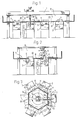
- Each of the plants shown in Figures 1 to 3 comprises a robot 2 mounted on a stand 1, and a number of work stations 3 served by the robot 2, the operating arm 4 of the robot being movable to each work station 3 from a starting position near the carrying body 5 of the robot.
- the work area of the robot is divided into two different spaces 6, 7, separated by a barrier 8 in the form of a safety roof or safety wall.
- the robot 2 is disposed in one space 6 and is able to move freely within this space 6, limited by the work area of the robot 2 and the barrier 8.
- the robot 2 In the second space 7, below the safety roof and beside the safety guard, respectively, the robot 2 only has access to those places where there are openings 9 between the spaces 6, 7.
- openings 9 The size of these openings 9 is adjusted to the actual operation and the openings 9 are provided with hatches 10 and guards 11. During servicing the guards 11 are moved aside and the hatch 10 is closed, thus denying the robot 2 access.
- the barriers 8 have sufficient strength to prevent the robot 2 from breaking through them.
- a suitable material is a net of wire. Such a wire netting is thus transparent in an advantageous manner.
- Figure 4 of the drawings shows a telescope arrangement for vertical lifts, known as a z-arm, for a portal robot carrying tools serving one or more work stations.
- a telescope arrangement is shown schematically in Figure 1 where the operating arm 5 is thus a vertically movable telescopic lifting arm.
- This embodiment of the invention offers a vertically operating portal robot arm with a telescopic lifting arm (z), which is thus able to operate under lower ceiling than a whole lifting arm.
- the telescopic arrangement comprises a fixed casing tube 21 rigid strictlyly mounted in the horizontal carriage 23 of the portal robot, a first telescope part 22 (z 1 ) running inside the tube 21.
- a second telescope part 24 (z 2 ) runs inside the first telescope part 22.
- a tool holder is designated 25 and is mounted on the lower end of the second telescope part 24.
- Secured to the lower portion of the second telescope part 24 is a continuous flexible hoisting means in the form of a hoisting chain or belt 26 for lifting.
- the hoisting chain or belt 26 runs over a tension wheel 27, a drive wheel 28, and a tension wheel 29 and is secured to a tension spring 30 for varying take-up of length.
- the tension spring 30 is mounted in the slack portion end of the hoisting chain or belt 26 to take up "excess length" when the second telescope part 24 is telescopically retracted.
- the tension spring 30 for the hoisting chain or belt 26 is secured inside the first telescope part 22 at point 31.
- the drive wheel 28 for the hoisting chain or belt 26 can be driven by any type of rotating drive means, the movement of which being converted into a linear movement from rotation to translation.
- Two pulleys 32 mounted in the upper end of the first telescope part 22, are arranged for reverse direction of movement of the hoisting chain or belt 26.
- a pneumatic cylinder 33 with a movable piston joined to a piston rod 34 is disposed for performing retarding and propelling of the second telescope part 24 (up and down movement) when this is to be moved in relation to the first telescope part 22.
- the pneumatic cylinder 33 is regulated by an electrically controlled valve to which air enters one side of the piston when the second telescope part 24 is to be expelled from the first telescope part 22. This provides a balancing or counteracting force which prevents the first telescope part 22 from falling down over the second telescope part 24 due to gravity. In this way the hoisting chain or belt 26 can simultaneously lower both telescope parts 22, 24, these then functioning as a homogenous unit.
- the force in the pneumatic cylinder 33 only counterbalances the weight of the whole second telescope part 24, since the force in the hoisting chain or belt 26, which is secured to the second telescope part 24, holds both the load in the tool holder 25 and the two telescope parts 22, 24.
- this entire unit load, tools, telescope parts 22, 24
- the electric valve will then open by the action of a limit switch, whereupon the air on said piston side is pressed out through a throttle valve having limited drainage, and the second telescope part 24 will be compressed due to the continued pulling movement of the hoisting chain or belt 26 until it encounters an end-position stop.
- the hoisting chain or belt 26 will then be too long and the tension spring 30 will adjust and automatically keep the chain or belt taut.
- the piston rod end of the pneumatic cylinder 33 is secured to the upper part 35 of the second telescope part 24, the upper end of the pneumatic cylinder 33 being secured to the first telescope part 22 at a rigid attachment device 36.
- a stop device 37 in the form of a hydraulic shock-absorber is provided as end-position stop for the second telescope part 24 in the first tele scope part 22 during the upward movement.
- a stop device 38 in the form of a hydraulic shock-absorber is arranged as end-position stop for the first telescope part 22 in the outer, stationary tube 21 during upward movement.
- a stop device 39 in the form of a hydraulic shock-absorber is arranged as end-position stop which is common for the two telescope parts 22, 24 during downward movement.
- the outer tube 21 constitutes a stationary telescopic tube joined to the horizontal carriage 23 of the robot portal.
- the two tension wheels 27 and 29 are mounted on one side of the tube 21, with the drive wheel 28 between them.
- the hoisting chain or belt runs between these wheels which may consist of chain or teeth wheels. Any type of chains or belts can be used for the drive system, provided that they can be hooked onto the toothed surface of the intermediate drive wheel.
- the condition for the function is that the hoisting chain or belt is not allowed to be secured to surfaces along the two independently movable telescope tubes, nor to the outer tube.
- the inner, i.e. the first, telescope part 22 consists of a tube which runs inside the outer tube 21 via some form of slide bearings, linear bearings, ball bearings or runners.
- the outer, i.e. the second, telescope part 22 consists of a tube or rod which runs inside the first telescope part 22 via some form of slide bearings, linear bearings, ball bearings or runners.
- the hoisting chain or belt 26 of the drive system is joined at its lower end to the lower end of the second telescope part 24. Further, the hoisting chain or belt is joined to the upper end of the first telescope part 22, in this case over two pulleys 32, to a tension spring. By means of the pulleys 32 the upper end of the hoisting chain or belt is caused to turn and run down again in the first telescope part 22, so that the hoisting chain or belt 26 can be connected to the tension spring 30 for compensation of length. The lower end of the tension spring 30 is secured to the inside of the first telescope part 22.
- This arrangement allows the telescoping system to function so that when the drive wheel 28 retracts the second telescope part 24 into the first telescope part 22, the tension spring 30 will equalize and take up the excess length of the hoisting chain or belt 26. This occurs because the total length of the hoisting chain or belt corresponds to the fully expelled length of the two telescope parts 22, 24, and this length decreases as the telescope parts are drawn together.
- the pneumatic cylinder 33 As mentioned, by means of the pneumatic cylinder 33 a balance between the two telescope parts 22, 24 is produced and the order in which they shall telescope into each other in relation to the outer tube 21, in which they both run, can be determined.
- the compressive force of the pneumatic cylinder 33 corresponds to the entire inherent load of the first telescope part 22 and the force reserve corresponding to the acceleration force to which this inherent load is equivalent.
- this pneumatic cylinder is thus joined at its upper end to the first telescope part and at its lower end to the upper portion of the second telescope part 24.
- the cylinder is thus located inside the first telescope part 22 and is controlled via an electrically activated valve able to regulate the quantity and rate of flow of the air.
- a pressure regulator is connected before this valve, to control the force in the cylinder so that it counterbalances the inherent load and corresponding acceleration force of the first telescope part.
- the first telescope part will move out of the outer tube 21 as the drive wheel continues to feed out the hoisting chain or belt.
- a full downwardly running z-movement (z tot ) will have been completed with one and the same rotating drive unit when the two telescope parts have reached their lowermost end positions.
Landscapes
- Engineering & Computer Science (AREA)
- Robotics (AREA)
- Mechanical Engineering (AREA)
- Manipulator (AREA)
- Loading And Unloading Of Fuel Tanks Or Ships (AREA)
Priority Applications (1)
| Application Number | Priority Date | Filing Date | Title |
|---|---|---|---|
| AT89116648T ATE78206T1 (de) | 1988-09-15 | 1989-09-08 | Anlage fuer industrieroboter. |
Applications Claiming Priority (2)
| Application Number | Priority Date | Filing Date | Title |
|---|---|---|---|
| SE8803255A SE460530C (sv) | 1988-09-15 | 1988-09-15 | Anläggning för robotoperationer |
| SE8803255 | 1988-09-15 |
Publications (2)
| Publication Number | Publication Date |
|---|---|
| EP0361178A1 true EP0361178A1 (de) | 1990-04-04 |
| EP0361178B1 EP0361178B1 (de) | 1992-07-15 |
Family
ID=20373336
Family Applications (1)
| Application Number | Title | Priority Date | Filing Date |
|---|---|---|---|
| EP89116648A Expired - Lifetime EP0361178B1 (de) | 1988-09-15 | 1989-09-08 | Anlage für Industrieroboter |
Country Status (4)
| Country | Link |
|---|---|
| EP (1) | EP0361178B1 (de) |
| AT (1) | ATE78206T1 (de) |
| DE (1) | DE68902120T2 (de) |
| SE (2) | SE8803255D0 (de) |
Cited By (7)
| Publication number | Priority date | Publication date | Assignee | Title |
|---|---|---|---|---|
| EP1375088A1 (de) * | 2002-06-21 | 2004-01-02 | ABB PATENT GmbH | Schutzeinrichtung für eine Roboteranlage |
| EP1704105A2 (de) | 2003-11-25 | 2006-09-27 | Hauni Maschinenbau AG | Anordnung zum befüllen und/oder entleeren von mit artikeln gefüllten und/oder zu befüllenden behältern sowie handhabungsvorrichtung zum transportieren der behälter |
| NL1037446C2 (nl) * | 2009-05-15 | 2010-11-18 | Wals Systems B V | Verplaatsingsinrichting |
| CN111906757A (zh) * | 2020-09-01 | 2020-11-10 | 上海松盛机器人系统有限公司 | 一种坐标机器人双节提升轴机构 |
| EP3878611A1 (de) * | 2020-03-10 | 2021-09-15 | Hochschule für angewandte Wissenschaften Landshut | Teilweise automatisierte herstellungszelle |
| CN118456502A (zh) * | 2024-07-09 | 2024-08-09 | 内蒙古正大有限公司 | 一种饲料搬运机械手防护安全装置 |
| US12552420B2 (en) | 2020-11-23 | 2026-02-17 | Autostore Technology AS | Service vehicle with a vehicle pen |
Families Citing this family (1)
| Publication number | Priority date | Publication date | Assignee | Title |
|---|---|---|---|---|
| DE102010034167A1 (de) | 2010-08-13 | 2012-02-16 | Mühlbauer Ag | System und Verfahren zum Bearbeiten von Sicherheits- oder Identifikationsgegenständen |
-
1988
- 1988-09-15 SE SE8803255D patent/SE8803255D0/xx not_active Application Discontinuation
- 1988-09-15 SE SE8803255A patent/SE460530C/sv not_active IP Right Cessation
-
1989
- 1989-09-08 AT AT89116648T patent/ATE78206T1/de not_active IP Right Cessation
- 1989-09-08 DE DE8989116648T patent/DE68902120T2/de not_active Expired - Fee Related
- 1989-09-08 EP EP89116648A patent/EP0361178B1/de not_active Expired - Lifetime
Non-Patent Citations (3)
| Title |
|---|
| "Nya Skyddsmojligheter i Arbetet Vid Industrirobotar" Transport Teknik Skandinavia 10/1986 (PAUL E BRANKE) * |
| Pratiska Skyddslosningar IVF-Skrift 88817 Praktiska Skyddslosningar - Industrirobotar Och Andra Maskiner (MATS LINGER) s. 6-9, Juni 1988 * |
| Symposium on Industrial Robots 7th International Conf. on Ind. Robot Tehg. (N. MARTENSSON) s. 119-129, 2 Oktober 1984 * |
Cited By (10)
| Publication number | Priority date | Publication date | Assignee | Title |
|---|---|---|---|---|
| EP1375088A1 (de) * | 2002-06-21 | 2004-01-02 | ABB PATENT GmbH | Schutzeinrichtung für eine Roboteranlage |
| EP1704105A2 (de) | 2003-11-25 | 2006-09-27 | Hauni Maschinenbau AG | Anordnung zum befüllen und/oder entleeren von mit artikeln gefüllten und/oder zu befüllenden behältern sowie handhabungsvorrichtung zum transportieren der behälter |
| CN1882485B (zh) * | 2003-11-25 | 2010-11-03 | 豪尼机械制造股份公司 | 装填和/或清空装有物品和/或需要装入物品的容器的设备及运送容器的操作装置 |
| US7909557B2 (en) | 2003-11-25 | 2011-03-22 | Hauni Maschinenbau Ag | Arrangement for the filling and/or emptying of containers filled and/or for filling with articles and manipulation device for transporting the containers |
| NL1037446C2 (nl) * | 2009-05-15 | 2010-11-18 | Wals Systems B V | Verplaatsingsinrichting |
| EP3878611A1 (de) * | 2020-03-10 | 2021-09-15 | Hochschule für angewandte Wissenschaften Landshut | Teilweise automatisierte herstellungszelle |
| WO2021180690A1 (en) * | 2020-03-10 | 2021-09-16 | Hochschule für angewandte Wissenschaften Landshut | Partially automated manufacturing cell |
| CN111906757A (zh) * | 2020-09-01 | 2020-11-10 | 上海松盛机器人系统有限公司 | 一种坐标机器人双节提升轴机构 |
| US12552420B2 (en) | 2020-11-23 | 2026-02-17 | Autostore Technology AS | Service vehicle with a vehicle pen |
| CN118456502A (zh) * | 2024-07-09 | 2024-08-09 | 内蒙古正大有限公司 | 一种饲料搬运机械手防护安全装置 |
Also Published As
| Publication number | Publication date |
|---|---|
| DE68902120T2 (de) | 1993-01-21 |
| EP0361178B1 (de) | 1992-07-15 |
| SE8803255D0 (sv) | 1988-09-15 |
| DE68902120D1 (de) | 1992-08-20 |
| ATE78206T1 (de) | 1992-08-15 |
| SE460530C (sv) | 1995-10-16 |
| SE460530B (sv) | 1989-10-23 |
Similar Documents
| Publication | Publication Date | Title |
|---|---|---|
| US3760956A (en) | Industrial robot | |
| US7108125B2 (en) | Extendable belt conveyor | |
| KR850000549B1 (ko) | 공업용 로보트 | |
| US5423163A (en) | Free standing pallet wrapping apparatus | |
| US3935950A (en) | Industrial robot | |
| EP0361178B1 (de) | Anlage für Industrieroboter | |
| JP2010540259A (ja) | パレタイザーのためのハンドリングロボット | |
| CN109823985B (zh) | 一种智能防护式举升机 | |
| EP0608487A1 (de) | Regalbedienungsgerät | |
| US4553743A (en) | Elevated device for placing slag retention means in tapping converters | |
| EP1052212A1 (de) | Einrichtung zur Ausführung von Arbeiten in einem Aufzugsschacht | |
| CN113830709A (zh) | 双回转伸缩变幅升降平台、调平机构液压系统及控制方法 | |
| EP1050505B1 (de) | Einrichtung zur Ausführung von Arbeiten in einem Aufzugsschacht | |
| CA1326245C (en) | Pneumatic door operator | |
| CA1048170A (en) | Gamma-irradiation treatment apparatus | |
| US3040911A (en) | Automatic feeder | |
| US3788491A (en) | Apparatus for moving an object along a predetermined path | |
| CN221850097U (zh) | 一种可调节的设备检修台 | |
| CN2048776U (zh) | 舞台防火幕及闭合速度控制装置 | |
| CN217350648U (zh) | 自动定量升降的升降平台 | |
| CN213446090U (zh) | 一种双立柱码桶机构 | |
| CN218114704U (zh) | 一种带有缓冲装置的电梯自救装置 | |
| KR102761035B1 (ko) | 배출 소재 자동 적재장치 | |
| KR0150563B1 (ko) | 차체 패널 운반장치 | |
| JPH0451029Y2 (de) |
Legal Events
| Date | Code | Title | Description |
|---|---|---|---|
| PUAI | Public reference made under article 153(3) epc to a published international application that has entered the european phase |
Free format text: ORIGINAL CODE: 0009012 |
|
| AK | Designated contracting states |
Kind code of ref document: A1 Designated state(s): AT BE CH DE FR GB IT LI LU NL SE |
|
| 17P | Request for examination filed |
Effective date: 19901004 |
|
| 17Q | First examination report despatched |
Effective date: 19911111 |
|
| GRAA | (expected) grant |
Free format text: ORIGINAL CODE: 0009210 |
|
| AK | Designated contracting states |
Kind code of ref document: B1 Designated state(s): AT BE CH DE FR GB IT LI LU NL SE |
|
| REF | Corresponds to: |
Ref document number: 78206 Country of ref document: AT Date of ref document: 19920815 Kind code of ref document: T |
|
| REF | Corresponds to: |
Ref document number: 68902120 Country of ref document: DE Date of ref document: 19920820 |
|
| ET | Fr: translation filed | ||
| ITF | It: translation for a ep patent filed | ||
| PG25 | Lapsed in a contracting state [announced via postgrant information from national office to epo] |
Ref country code: LU Free format text: LAPSE BECAUSE OF NON-PAYMENT OF DUE FEES Effective date: 19920930 |
|
| PLBE | No opposition filed within time limit |
Free format text: ORIGINAL CODE: 0009261 |
|
| STAA | Information on the status of an ep patent application or granted ep patent |
Free format text: STATUS: NO OPPOSITION FILED WITHIN TIME LIMIT |
|
| 26N | No opposition filed | ||
| EAL | Se: european patent in force in sweden |
Ref document number: 89116648.0 |
|
| PGFP | Annual fee paid to national office [announced via postgrant information from national office to epo] |
Ref country code: FR Payment date: 19960823 Year of fee payment: 8 |
|
| PGFP | Annual fee paid to national office [announced via postgrant information from national office to epo] |
Ref country code: AT Payment date: 19960828 Year of fee payment: 8 |
|
| PGFP | Annual fee paid to national office [announced via postgrant information from national office to epo] |
Ref country code: GB Payment date: 19960830 Year of fee payment: 8 |
|
| PGFP | Annual fee paid to national office [announced via postgrant information from national office to epo] |
Ref country code: BE Payment date: 19960911 Year of fee payment: 8 |
|
| PGFP | Annual fee paid to national office [announced via postgrant information from national office to epo] |
Ref country code: NL Payment date: 19960930 Year of fee payment: 8 |
|
| PGFP | Annual fee paid to national office [announced via postgrant information from national office to epo] |
Ref country code: DE Payment date: 19961126 Year of fee payment: 8 |
|
| PGFP | Annual fee paid to national office [announced via postgrant information from national office to epo] |
Ref country code: CH Payment date: 19970103 Year of fee payment: 8 |
|
| PG25 | Lapsed in a contracting state [announced via postgrant information from national office to epo] |
Ref country code: GB Free format text: LAPSE BECAUSE OF NON-PAYMENT OF DUE FEES Effective date: 19970908 Ref country code: AT Free format text: LAPSE BECAUSE OF NON-PAYMENT OF DUE FEES Effective date: 19970908 |
|
| PG25 | Lapsed in a contracting state [announced via postgrant information from national office to epo] |
Ref country code: LI Free format text: LAPSE BECAUSE OF NON-PAYMENT OF DUE FEES Effective date: 19970930 Ref country code: BE Free format text: LAPSE BECAUSE OF NON-PAYMENT OF DUE FEES Effective date: 19970930 Ref country code: FR Free format text: THE PATENT HAS BEEN ANNULLED BY A DECISION OF A NATIONAL AUTHORITY Effective date: 19970930 Ref country code: CH Free format text: LAPSE BECAUSE OF NON-PAYMENT OF DUE FEES Effective date: 19970930 |
|
| BERE | Be: lapsed |
Owner name: TRANSMAN A.B. Effective date: 19970930 |
|
| PG25 | Lapsed in a contracting state [announced via postgrant information from national office to epo] |
Ref country code: NL Free format text: LAPSE BECAUSE OF NON-PAYMENT OF DUE FEES Effective date: 19980401 |
|
| GBPC | Gb: european patent ceased through non-payment of renewal fee |
Effective date: 19970908 |
|
| REG | Reference to a national code |
Ref country code: CH Ref legal event code: PL |
|
| NLV4 | Nl: lapsed or anulled due to non-payment of the annual fee |
Effective date: 19980401 |
|
| PG25 | Lapsed in a contracting state [announced via postgrant information from national office to epo] |
Ref country code: DE Free format text: LAPSE BECAUSE OF NON-PAYMENT OF DUE FEES Effective date: 19980603 |
|
| REG | Reference to a national code |
Ref country code: FR Ref legal event code: ST |
|
| PG25 | Lapsed in a contracting state [announced via postgrant information from national office to epo] |
Ref country code: IT Free format text: LAPSE BECAUSE OF NON-PAYMENT OF DUE FEES;WARNING: LAPSES OF ITALIAN PATENTS WITH EFFECTIVE DATE BEFORE 2007 MAY HAVE OCCURRED AT ANY TIME BEFORE 2007. THE CORRECT EFFECTIVE DATE MAY BE DIFFERENT FROM THE ONE RECORDED. Effective date: 20050908 |
|
| PGFP | Annual fee paid to national office [announced via postgrant information from national office to epo] |
Ref country code: SE Payment date: 20080910 Year of fee payment: 20 |
|
| EUG | Se: european patent has lapsed |