EP0361207A1 - Petit bateau à propulsion par jet - Google Patents
Petit bateau à propulsion par jet Download PDFInfo
- Publication number
- EP0361207A1 EP0361207A1 EP89116886A EP89116886A EP0361207A1 EP 0361207 A1 EP0361207 A1 EP 0361207A1 EP 89116886 A EP89116886 A EP 89116886A EP 89116886 A EP89116886 A EP 89116886A EP 0361207 A1 EP0361207 A1 EP 0361207A1
- Authority
- EP
- European Patent Office
- Prior art keywords
- bulwarks
- jet propulsion
- boat
- small boat
- container
- Prior art date
- Legal status (The legal status is an assumption and is not a legal conclusion. Google has not performed a legal analysis and makes no representation as to the accuracy of the status listed.)
- Granted
Links
- 229920003002 synthetic resin Polymers 0.000 claims abstract description 4
- 239000000057 synthetic resin Substances 0.000 claims abstract description 4
- 238000005192 partition Methods 0.000 claims description 7
- 239000006260 foam Substances 0.000 claims 1
- 238000007789 sealing Methods 0.000 abstract description 2
- XLYOFNOQVPJJNP-UHFFFAOYSA-N water Substances O XLYOFNOQVPJJNP-UHFFFAOYSA-N 0.000 description 10
- 230000033001 locomotion Effects 0.000 description 4
- 230000000630 rising effect Effects 0.000 description 3
- 238000010276 construction Methods 0.000 description 1
- 238000006073 displacement reaction Methods 0.000 description 1
- 230000000694 effects Effects 0.000 description 1
- 230000001747 exhibiting effect Effects 0.000 description 1
- 230000037431 insertion Effects 0.000 description 1
- 238000003780 insertion Methods 0.000 description 1
- 230000009191 jumping Effects 0.000 description 1
Images


Classifications
-
- B—PERFORMING OPERATIONS; TRANSPORTING
- B63—SHIPS OR OTHER WATERBORNE VESSELS; RELATED EQUIPMENT
- B63B—SHIPS OR OTHER WATERBORNE VESSELS; EQUIPMENT FOR SHIPPING
- B63B34/00—Vessels specially adapted for water sports or leisure; Body-supporting devices specially adapted for water sports or leisure
- B63B34/10—Power-driven personal watercraft, e.g. water scooters; Accessories therefor
Definitions
- the invention relates to a jet propulsion small boat as indicated in the introductory portion of the main claim, which runs on the sea surface at a high speed with at least one rider on it, enabling also to make use of the boat for other activities such as fishing, leaving the boat drifting on the sea surface.
- jet propulsion small boats which are engined small boats for gliding on the water surface like a motor-bike type jet propulsion boat.
- a jet propulsion boat is used for practising various motions such as slaloming, jumping, tricking, etc, while gliding at high speed on the water surface, driven through the power of the engine aboard.
- the boat is provided with seats on the hull centre line including, for example, a seat bench and an operating handle bar stand on its front portion in order to operate the boat by a rider sitting astride the seat with his feet placed on the decks on either side.
- Such a jet propulsion small boat is also frequently used as a fishing boat.
- the boat hull is desired to have a large righting moment while being constructed compactly to obtain an excellent movability.
- a jet propulsion boat comprising a deck member and a hull member both integrally formed from synthetic resin such as FRP and bonded with each other at their fringe portions, respectively.
- the objectives of the present invention are performed through the deck member comprising bulwarks formed at the deck member's fringe portions except at its stern end, a seat stand and an operating handle stand projectingly formed on the hull centre line, and decks formed at least on both sides of these stands designing the bulwarks to define buoyancy spaces to function as floats, and to define at least one longitudinally extending container through said bulwarks with a respective opening at the rear end portion thereof to allow access to the internal space of the container with said rear opening detachably mounting a lid with a watertight structure to sealingly close said opening.
- the bulwarks in themselves define at least one longitudinally extending container as an integral part with a rear opening formed at the relevant end portion thereof detachably mounting a lid with a watertight structure to sealingly close said opening.
- said bulwarks extending longitudinally at both sides of the boat each provide a longitudinal extending container as an integral part thereof, thus providing a pair of longitudinally extending containers inside the side bulwarks of the boat, each having a respective opening formed at each of the bulwarks rear end portions and the respective lid with a watertight structure detachably mounted on each of said openings, respectively.
- said bularks form buoyancy spaces receiving longitudinally extending partition walls which are preferably horizontally orientated to separate said container space for receiving the fishing rods or the like above said partition wall adapted to define the container.
- the insertion of partition walls could be prevented by means of a pipe member which forms a container by means of its elongated interior tubular space, said pipe member being disposed in the upper portion of one or both longitudinally extending buoyancy spaces formed by the bulwarks with a lid having a watertight structure being detachably mounted on the rear end portion of the pipe member in order to sealingly close the tube at its rear end, respectively.
- the separated container space may also serve to form a tank to be filled with water after overturning of the boat, if such an introduction of water can assist righting of the boat.
- the boat hull 1 is composed of a hull member 2 and a deck member both integrally formed from synthetic resin such as FRP and bonded with each other at their fringe portions, respectively.
- the portion surrounded by the hull member 2 and the deck members is designed to form a hermetically sealed space to define a displacement volume.
- the hull member 2 has a bottom plate, 20 and side plates 22 and the deck member provides a seat stand 5 projectingly formed at its centre portion, rising portions 31 formed at its fringes except at its stern end with their upper end portions folded back as back-folded portions 33, the lower end portions of which are put upon and bonded with the upper end portions of the hull side plates 22 to form bonded portions 23.
- buoyancy spaces 30 are formed comprised of hermetically sealed spaces, and bulwarks 8 are established defining said buoyancy spaces 30.
- bulwarks 8 are established defining said buoyancy spaces 30.
- FIGs 1 and 2 there are longitudinally extending horizontal partition walls 81 received within these buoyancy spaces 30 to form container 80 above said partition walls inside the bulwarks for containing fishing rods 11 or the like.
- access openings to said containers 80 each of said openings being provided with a lid 88 detachably mounted thereto and provided in turn with a watertight structure to sealingly close the associated opening.
- the deck member implies a seat stand 5 and an operating handle stand 6 projectingly formed on the hull centre line. Between the bulwarks and these stands 5, 6 and both sides of these stands are formed decks 3 with open stern ends and continued to each other at the bow portion to form a single plane.
- the operating handle stand 6 supports an operating handle 60 and a seat 50, preferably forming a seat bench and a seat 51 is formed on the rear and front portions of the seat stand 5, respectively.
- footings 35 enabling the driver to keep his feet against them while gliding at a high speed.
- footrests are not obligatory or could have other structures, for example, such footings could provide to adjust their height variably.
- an engine room 12 in which an engine (not shown) and other components of the boat's driving means are received, said engine rotates a propeller (not shown) to suck in water through a water suction opening at the hull bottom and inject it backwards in a desired direction through a water passage and then through a horizontally swingable nozzle at the stern of the boat to produce a propelling force and a turning force, respectively.
- a propeller not shown
- the upper container providing interior spaces 80 to receive fishing rods and the like therein could also be provided separated from the remaining buoyancy space to form a separable part of the bulwarks 8, i.e. the container 80 as shown in Fig 2 could form separate hollow profile members piled up on the lower bulwark portion and fixed thereon by suitable fasteners so that one or both containers 80 could be separated from the body of the boat.
- the buoyancy spaces 30 would then be closed by an upper cover plate, namely, a back-folded portion 33 of the deck member to provide an airtightly sealed buoyancy space 30 defined by the corresponding bulwarks 8, respectively.
- the integral structure of the container 80, 90 separated from the continuous bulwarks 8, as shown in Figs 1 to 3, is preferred.
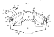
- Fig 3 shows another embodiment of the invention. While the main portions of the boat hull 1 and also the bulwarks 8 with the buoyancy spaces 30 formed by rising walls 31, back-folded portions 33 and boat hull side plates 22 remain the same and are structured in the same way as shown in the above-mentioned first embodiment according to Figs 1 and 2, in this case a pipe member 9 forming a container 90 by means of its elongated interior space is disposed in the upper portion of preferably each buoyancy space 30 allowing to refrain from a separate partition wall. Even though not shown in the drawing, a lid 88 with a watertight sealing structure as shown in Fig 1 is provided on the rear end portion of this pipe member 9, detachably mounted thereon.
- This pipe member 9 is fixed on the inside surface of the bulwarks 8 through a pair of U-shaped fasteners 91 and the space around the pipe member 9 is filled up by foamed plastic. Occasionally, separate fasteners could be dispensable and the porous structure of the foamed plastic could prove to be sufficient to fix the pipe member 9.
- the boat according to this invention since the bulwarks 8 on both sides of the boat hull have buoyancy spaces 80 having a large buoyancy, the boat according to this invention has a large righting moment and exhibits an excellent stability for various movements while gliding, even when the boat suffers a large inclining moment due to a rapid turn.
- the bulwarks 8 can effectively function as floats because the container 80 or 90 is hermetically closed by a lid 88 with a watertight structure so that water may not come into the container. Further, if the boat hull 1 is overturned by 180°, the boat hull 1 can easily be righted by opening either of the lids 88 and introducing water into the related container 80 or 90 to reduce its buoyancy.
- the container 80 or 90 is not a hindrance to riders moving on board since it is formed within the original boat hull structure and will not project out of the boat hull, and there is no fear that fishing rods or the like should be carried away even when waves dash over the boat hull.
- the structure is simple and also advantageous for strength that the opening and the lid 88 for the container 80 or 90 are provided at the rear end portion of the bulwarks. That is to say, it is because forming the opening of the container on the top or side of the bulwarks not only lengthens the opening making its structure intricate but also makes it difficult to obtain a watertight structure and weakens the bulwarks.
Landscapes
- Chemical & Material Sciences (AREA)
- Engineering & Computer Science (AREA)
- Combustion & Propulsion (AREA)
- Mechanical Engineering (AREA)
- Ocean & Marine Engineering (AREA)
- Helmets And Other Head Coverings (AREA)
- Toys (AREA)
- Cleaning Or Clearing Of The Surface Of Open Water (AREA)
- Vibration Prevention Devices (AREA)
Applications Claiming Priority (2)
| Application Number | Priority Date | Filing Date | Title |
|---|---|---|---|
| JP242126/88 | 1988-09-26 | ||
| JP63242126A JP3053185B2 (ja) | 1988-09-26 | 1988-09-26 | 小型ジェット推進艇 |
Publications (2)
| Publication Number | Publication Date |
|---|---|
| EP0361207A1 true EP0361207A1 (fr) | 1990-04-04 |
| EP0361207B1 EP0361207B1 (fr) | 1993-12-15 |
Family
ID=17084688
Family Applications (1)
| Application Number | Title | Priority Date | Filing Date |
|---|---|---|---|
| EP89116886A Expired - Lifetime EP0361207B1 (fr) | 1988-09-26 | 1989-09-12 | Petit bateau à propulsion par jet |
Country Status (4)
| Country | Link |
|---|---|
| US (1) | US5095843A (fr) |
| EP (1) | EP0361207B1 (fr) |
| JP (1) | JP3053185B2 (fr) |
| ES (1) | ES2049289T3 (fr) |
Families Citing this family (17)
| Publication number | Priority date | Publication date | Assignee | Title |
|---|---|---|---|---|
| USD348648S (en) | 1993-05-28 | 1994-07-12 | Uribe Juan E | Universal slip-in seat for stand-up jet ski |
| US5676086A (en) * | 1996-09-09 | 1997-10-14 | Yamaha Hatsudoki Kabushiki Kaisha | Rear storage assembly for watercraft |
| JP3995064B2 (ja) * | 1997-03-21 | 2007-10-24 | ヤマハ発動機株式会社 | 船艇の物入れ装置 |
| US6702629B2 (en) | 1999-08-09 | 2004-03-09 | Bombardier Motor Corporation Of America | Watercraft with improved stability |
| US20040031430A1 (en) * | 1999-08-09 | 2004-02-19 | Bombardier Motor Corporation Of America | Deck boat |
| US6701863B2 (en) | 1999-08-09 | 2004-03-09 | Bombardier Recreational Products Inc. | Watercraft with collapsible privacy compartment |
| US6672240B1 (en) * | 1999-08-09 | 2004-01-06 | Bombardier Motor Corporation Of America | Deck boat |
| US6766759B2 (en) | 1999-08-09 | 2004-07-27 | Bombardier Recreational Products Inc. | Watercraft with flexible seating configurations |
| US6837173B2 (en) | 2001-08-01 | 2005-01-04 | Bombardier Recreational Products Inc. | Watercraft |
| US20060000407A1 (en) * | 2004-07-01 | 2006-01-05 | Deane Henderson | Under-gunnel locker door |
| CN100391786C (zh) * | 2004-09-14 | 2008-06-04 | 杭州飞鹰船艇有限公司 | 一种新型赛艇 |
| USD703007S1 (en) | 2009-08-20 | 2014-04-22 | Anthony E. McCarthy | Cooler device for personal watercrafts |
| JP2011088524A (ja) * | 2009-10-21 | 2011-05-06 | Yamaha Motor Co Ltd | 水ジェット推進艇 |
| US9365268B1 (en) | 2012-07-16 | 2016-06-14 | Bombardier Recreational Products Inc. | Fender for a watercraft |
| CN105059475A (zh) * | 2015-08-12 | 2015-11-18 | 上海船舶研究设计院 | 一种水下探测船的可拆式舷墙结构 |
| US10011327B2 (en) * | 2016-07-27 | 2018-07-03 | Yamaha Hatsudoki Kabushiki Kaisha | Watercraft |
| CN111483549B (zh) * | 2020-05-14 | 2021-04-09 | 辽宁锦龙超级游艇制造有限公司 | 一种游艇防溺水保护作用的装置 |
Citations (3)
| Publication number | Priority date | Publication date | Assignee | Title |
|---|---|---|---|---|
| DE3030469A1 (de) * | 1980-08-08 | 1982-11-04 | GST Gesellschaft für Surftechnologie und -produktion mbH, 1000 Berlin | Surfbrett |
| WO1985001486A1 (fr) * | 1983-09-26 | 1985-04-11 | Kitner William M | Structure de flottaison stabilisatrice pour embarcations |
| US4760810A (en) * | 1985-11-21 | 1988-08-02 | Yamaha Hatsudoki Kabushiki Kaisha | Hull for small watercraft |
Family Cites Families (12)
| Publication number | Priority date | Publication date | Assignee | Title |
|---|---|---|---|---|
| US611021A (en) * | 1898-09-20 | Life-boat | ||
| US883588A (en) * | 1906-05-16 | 1908-03-31 | Caleb B Thatcher | Invisible air-chamber and sponson for canoes. |
| US2848725A (en) * | 1955-05-03 | 1958-08-26 | Milton O Sloulin | Safety attachment for boats |
| DE1303046B (fr) * | 1965-04-30 | 1971-06-09 | Fa Carl Still | |
| US3665532A (en) * | 1970-03-27 | 1972-05-30 | Lawrence V Simpson | Watercraft |
| JPS565754B2 (fr) * | 1973-05-25 | 1981-02-06 | ||
| US3952350A (en) * | 1974-10-04 | 1976-04-27 | Emil Moucka | Gravity weight trigger for a life raft |
| JPS5310157A (en) * | 1976-07-14 | 1978-01-30 | Sanyo Electric Co Ltd | Air heat source type air conditioner |
| US4161796A (en) * | 1977-06-07 | 1979-07-24 | Kransco Manufacturing, Inc. | Monolithic polymer foam sailboat hull |
| US4468118A (en) * | 1982-09-17 | 1984-08-28 | At&T Technologies, Inc. | Method and apparatus for determining index of refraction profiles of optical fibers |
| JPH0712839B2 (ja) * | 1985-11-26 | 1995-02-15 | ヤマハ発動機株式会社 | 小型ジエツト推進艇 |
| KR890009172Y1 (ko) * | 1987-01-09 | 1989-12-18 | 최태진 | 안전보트 |
-
1988
- 1988-09-26 JP JP63242126A patent/JP3053185B2/ja not_active Expired - Fee Related
-
1989
- 1989-09-12 ES ES89116886T patent/ES2049289T3/es not_active Expired - Lifetime
- 1989-09-12 EP EP89116886A patent/EP0361207B1/fr not_active Expired - Lifetime
-
1991
- 1991-05-06 US US07/700,335 patent/US5095843A/en not_active Expired - Fee Related
Patent Citations (3)
| Publication number | Priority date | Publication date | Assignee | Title |
|---|---|---|---|---|
| DE3030469A1 (de) * | 1980-08-08 | 1982-11-04 | GST Gesellschaft für Surftechnologie und -produktion mbH, 1000 Berlin | Surfbrett |
| WO1985001486A1 (fr) * | 1983-09-26 | 1985-04-11 | Kitner William M | Structure de flottaison stabilisatrice pour embarcations |
| US4760810A (en) * | 1985-11-21 | 1988-08-02 | Yamaha Hatsudoki Kabushiki Kaisha | Hull for small watercraft |
Also Published As
| Publication number | Publication date |
|---|---|
| EP0361207B1 (fr) | 1993-12-15 |
| JP3053185B2 (ja) | 2000-06-19 |
| JPH0288388A (ja) | 1990-03-28 |
| US5095843A (en) | 1992-03-17 |
| ES2049289T3 (es) | 1994-04-16 |
Similar Documents
| Publication | Publication Date | Title |
|---|---|---|
| EP0361207B1 (fr) | Petit bateau à propulsion par jet | |
| EP0361149A1 (fr) | Petit bateau à propulsion par jet | |
| JP3242483B2 (ja) | 小型船舶の船体構造 | |
| US5050517A (en) | Small sized jet propulsion boat | |
| US3471875A (en) | Portable fishing float | |
| US4512275A (en) | Unsinkable all-purpose boat | |
| US5257594A (en) | Suitcase boat | |
| US6651573B2 (en) | Personal watercraft | |
| CN101092159A (zh) | 可拆组的携带式水上交通工具 | |
| US5038694A (en) | Small sailing ship | |
| US4827859A (en) | Boat | |
| US3649977A (en) | Self-bailing formed skin/scuba diver{40 s float | |
| US6354238B1 (en) | Collapsible bait tank for sealed bulkhead installation | |
| JP3184228U (ja) | 自動車用ルーフボックス | |
| WO1988005745A1 (fr) | Embarcation | |
| JP2621113B2 (ja) | 小型ジエツト推進艇 | |
| JPS62125984A (ja) | 小型ジエツト推進艇 | |
| KR200305892Y1 (ko) | 1인승안전선박구조 | |
| JPS62125983A (ja) | 小型ジエツト推進艇の物入れの構造 | |
| JP2535530B2 (ja) | 小型ジエツト推進艇 | |
| RU2003580C1 (ru) | Лодка | |
| JP2746366B2 (ja) | 小型ジエツト推進艇 | |
| EP0360051B1 (fr) | Petit bateau à propulsion par réaction | |
| KR20120075789A (ko) | 수상운송장치 | |
| JPS62125991A (ja) | 小型船舶 |
Legal Events
| Date | Code | Title | Description |
|---|---|---|---|
| PUAI | Public reference made under article 153(3) epc to a published international application that has entered the european phase |
Free format text: ORIGINAL CODE: 0009012 |
|
| AK | Designated contracting states |
Kind code of ref document: A1 Designated state(s): ES FR IT |
|
| 17P | Request for examination filed |
Effective date: 19901004 |
|
| 17Q | First examination report despatched |
Effective date: 19911213 |
|
| GRAA | (expected) grant |
Free format text: ORIGINAL CODE: 0009210 |
|
| AK | Designated contracting states |
Kind code of ref document: B1 Designated state(s): ES FR IT |
|
| ITF | It: translation for a ep patent filed | ||
| ET | Fr: translation filed | ||
| REG | Reference to a national code |
Ref country code: ES Ref legal event code: FG2A Ref document number: 2049289 Country of ref document: ES Kind code of ref document: T3 |
|
| PLBE | No opposition filed within time limit |
Free format text: ORIGINAL CODE: 0009261 |
|
| STAA | Information on the status of an ep patent application or granted ep patent |
Free format text: STATUS: NO OPPOSITION FILED WITHIN TIME LIMIT |
|
| 26N | No opposition filed | ||
| PGFP | Annual fee paid to national office [announced via postgrant information from national office to epo] |
Ref country code: FR Payment date: 20010911 Year of fee payment: 13 |
|
| PGFP | Annual fee paid to national office [announced via postgrant information from national office to epo] |
Ref country code: ES Payment date: 20010920 Year of fee payment: 13 |
|
| PG25 | Lapsed in a contracting state [announced via postgrant information from national office to epo] |
Ref country code: ES Free format text: LAPSE BECAUSE OF NON-PAYMENT OF DUE FEES Effective date: 20020913 |
|
| PG25 | Lapsed in a contracting state [announced via postgrant information from national office to epo] |
Ref country code: FR Free format text: LAPSE BECAUSE OF NON-PAYMENT OF DUE FEES Effective date: 20030603 |
|
| REG | Reference to a national code |
Ref country code: FR Ref legal event code: ST |
|
| REG | Reference to a national code |
Ref country code: ES Ref legal event code: FD2A Effective date: 20031011 |
|
| PG25 | Lapsed in a contracting state [announced via postgrant information from national office to epo] |
Ref country code: IT Free format text: LAPSE BECAUSE OF NON-PAYMENT OF DUE FEES;WARNING: LAPSES OF ITALIAN PATENTS WITH EFFECTIVE DATE BEFORE 2007 MAY HAVE OCCURRED AT ANY TIME BEFORE 2007. THE CORRECT EFFECTIVE DATE MAY BE DIFFERENT FROM THE ONE RECORDED. Effective date: 20050912 |