EP0360051B1 - Petit bateau à propulsion par réaction - Google Patents
Petit bateau à propulsion par réaction Download PDFInfo
- Publication number
- EP0360051B1 EP0360051B1 EP89116139A EP89116139A EP0360051B1 EP 0360051 B1 EP0360051 B1 EP 0360051B1 EP 89116139 A EP89116139 A EP 89116139A EP 89116139 A EP89116139 A EP 89116139A EP 0360051 B1 EP0360051 B1 EP 0360051B1
- Authority
- EP
- European Patent Office
- Prior art keywords
- boat
- jet propulsion
- hull
- seat
- stern
- Prior art date
- Legal status (The legal status is an assumption and is not a legal conclusion. Google has not performed a legal analysis and makes no representation as to the accuracy of the status listed.)
- Expired - Lifetime
Links
Images

Classifications
-
- B—PERFORMING OPERATIONS; TRANSPORTING
- B63—SHIPS OR OTHER WATERBORNE VESSELS; RELATED EQUIPMENT
- B63B—SHIPS OR OTHER WATERBORNE VESSELS; EQUIPMENT FOR SHIPPING
- B63B13/00—Conduits for emptying or ballasting; Self-bailing equipment; Scuppers
-
- B—PERFORMING OPERATIONS; TRANSPORTING
- B63—SHIPS OR OTHER WATERBORNE VESSELS; RELATED EQUIPMENT
- B63B—SHIPS OR OTHER WATERBORNE VESSELS; EQUIPMENT FOR SHIPPING
- B63B34/00—Vessels specially adapted for water sports or leisure; Body-supporting devices specially adapted for water sports or leisure
- B63B34/10—Power-driven personal watercraft, e.g. water scooters; Accessories therefor
Definitions
- the invention relates to a jet propulsion small boat comprising a deck member and a hull member, both integrally formed of synthetic resin such as FRP, and bonded with each other at their fringe portions, said deck member comprises bulwarks formed at its fringe portions except the stern end of the deck member, a seat end and an operating handle stand, both projectionally formed on the hull centre line, said deck member comprising decks formed at both sides of the seat stand, such as fishing with the boat drifting on the sea surface.
- synthetic resin such as FRP
- a small jet propulsion boat which is engined for gliding on the water surface like a motor-cycle type jet boat. Since such a jet propulsion boat is used for practising various motions while gliding at a high speed on the water surface, it is provided with seats including, for example, a bench seat on the hull centre line, and an operating handle on its front portion to be operated by a rider sitting astride the seat with his feet placed on the decks on both sides thereof.
- jet propulsion boat practises various motions while gliding on the water surface at a high speed and thus waves are frequently apt to dash over the boat, it is necessary for the water thrown up on to the boat to be readily rejected and removed from the boat's deck surfaces.
- a jet propulsion boat is nowadays more and more utilised not only for gliding on the water surface but also for other purposes such as fishing, leaving the boat drifting on the sea surface, it is desirable for the rider on the boat to be able to move about on it easily and without discomfort.
- the afore-mentioned object is attained in that another deck is provided in front of the operating handle stand, all of these decks are integrally continuously formed with each other as a substantially single plane with their stern ends opened in order to allow water thrown up on board to be smoothly rejected from the rear end portions of the decks to their stern ends without staying on board, and a seat is provided in front of the operating handle stand.
- the decks are formed continuously integrally with each other as a generally single plane with the stern end of the boat's deck being unrestrictedly open, water thrown up on board can promptly be rejected from the boat's decks flowing off the stern ends thereof and, moreover, it is very easy for the rider or riders to move about the deck.
- the hull member comprises a bottom plate, side plates and a stern plate
- the deck member comprises rising portions formed at its fringes except at the stern end portion of the deck member, said rising portions having their upper end portions folded back put upon and bonded with the upper end portions of the hull side plates to form bonded portions with said rising portions of the deck member and said side plates of the hull member defining spaces therebeteween to establish said bulwarks, substantially supporting an increased stability of the boat.
- a plurality of seats or a bench seat and another seat are respectively provided to the rear and front portions of the seat stand, the latter being integrally provided with the deck portions.
- the boat can conveniently be used for fishing, leaving the boat drifting, designing said bulwarks to form footings while setting the seats higher than the bulwarks.
- a particular increased buoyancy can be obtained if the hull member and the deck member including the seat stand, operating handle stand and bulwarks are designed to form a hermetically sealed space to define displacement volume.
- said continued decks which form a generally single open-ended plane at the stern end portion of the boat, are set to be slightly inclined rearwardly when the boat is under way to promote the rejection of water from the deck.
- a compacted structure of the boat can be obtained in that an engine room is found beneath the operating handle stand and the seat stand adapted to receive at least an engine and a fuel tank, with the engine being provided to rotate a propeller to suck in water through a water suction opening at the hull bottom and to inject it backwards in a deisred direction through a water passage and then through a horizontally swingable nozzle at the stern of the boat to produce a propelling force and a turning force, respectively.
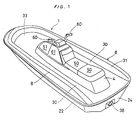
- the boat hull 1 is composed of a hull member 2 and a deck member 3 both integrally formed from synthetic resin such as FRP and bonded with each other at their respective fringe portions.
- the portion surrounded by the hull member 2 and the deck member 3 is formed as a hermetically sealed space to define an appropriate displacement volume.
- the hull member 2 has a bottom plate 20, side plates 22 and a stern plate 24 and the deck member 3 comprises rising portions 31 erecting at its fringes with the exception of the stern end of the boat, with the upper end portions of said rising portions 31 being folded back, put upon and bonded with the upper end portions of the hull side plates 22 to form the bonded portions 23.
- These rising portions 31 and the associated side plates 22 form spaces therebetween and thus establish bulwarks 8.
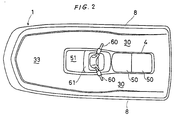
- the deck member 3 is provided with a seat stand 4 and an operating handle stand 61, both projectingly formed on the hull centre line and comprises decks 30 with open stern ends formed on both sides of these stands 4, 61 between the bulwarks 8 and these stands 4, 61 and, finally, a deck 33 is formed in front of these stands. All of these decks are integrally continuously formed with each other as a generally single plane.
- On the above-mentioned operating handle stand 61 is mountd an operating handle 60 and on the rear and front portions of the seat stand 4 are formed seats 50, preferably designed as a bench seat, and a seat 51, respectively.
- an engine room in which are arranged an engine 14, a fuel tank, etc, and by this engine 14 a propeller (not shown) is rotated to suck in water through the water suction opening 36 at the hull bottom and inject it backwards in a desired direction through the water passage 37 and then throughthe horizontally swingable nozzle 38 at the stern to produce a propelling force and a turning force.
- a propeller (not shown) is rotated to suck in water through the water suction opening 36 at the hull bottom and inject it backwards in a desired direction through the water passage 37 and then throughthe horizontally swingable nozzle 38 at the stern to produce a propelling force and a turning force.
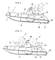
- the space on board can be effectively utilised by two riders by seating both riders fore and aft astride the seat 50 as shown in Fig 4 while gliding ordinarily, and also by seating one rider forward on the front seat 51 with his feet placed on the deck 33 and the other rider rearward on the seat 50 as shown in Fig 5, while lying at anchor offshore for fishing or the like.
- the rider can move about on boad the boat according to this invention very easily because the decks 30 and 33 continue to each other as a generally single plane.
Landscapes
- Chemical & Material Sciences (AREA)
- Engineering & Computer Science (AREA)
- Combustion & Propulsion (AREA)
- Mechanical Engineering (AREA)
- Ocean & Marine Engineering (AREA)
- Toys (AREA)
- Fire-Extinguishing By Fire Departments, And Fire-Extinguishing Equipment And Control Thereof (AREA)
- Escalators And Moving Walkways (AREA)
- Helmets And Other Head Coverings (AREA)
Claims (7)
- Bateau à propulsion par jet comportant un élément formant pont et un élément formant coque, tous deux formés de manière intégrale de résine synthétique telle que FRP, et reliés l'un à l'autre au niveau de leurs parties formant bord, ledit élément formant pont (3) comportant des bastingages (8) formés au niveau de sa partie formant bord sauf à l'extrémité arrière de l'élément formant pont (3), un support à extrémité formant siège (4) et un support (61) de poignée de fonctionnement, tous deux formés de manière à faire saillie sur l'axe central de la coque, ledit élément formant pont comportant des ponts (30) formés des deux cotés du support de siège, caractérisé en ce qu'un autre pont (33) est fourni à l'avant du support (61) de poignée de fonctionnement, tous ces ponts (30, 33) étant formés venus de matière de manière continue l'un par rapport à l'autre comme un plan unique en ayant leurs extrémités arrières ouvertes pour permettre à l'eau déversée à bord d'être rejetée doucement à partir des parties formant extrémités arrières des ponts (30) vers leurs extrémités arrières sans rester à bord, et en ce qu'un siège (51) est prévu en avant du support (61) de poignée de fonctionnement.
- Bateau à propulsion par jet selon la revendication 1, caractérisé en ce que l'élément formant coque (2) comporte une plaque de fond (20), des plaques latérales (22) et une plaque arrière (24),de telle sorte que l'élément formant coque (3) comporte des parties montantes (31) formées au niveau de ses bords, sauf à son extrémité arrière, leurs parties formant extrémités supérieures étant repliées, posées sur et reliées avec les parties formant extrémités supérieures des plaques latérales (2) de la coque pour former des parties (23) reliées, lesdites parties montantes (31) de l'élément formant pont (3) et les plaques (22) latérales de l'élément formant pont (2) définissant des espaces entre elles, formant ainsi lesdits bastingages (8).
- Bateau à propulsion par jet selon la revendication 1 ou 2, caractérisé en ce que plusieurs sièges (50) et un siège (51) sont respectivement fournis sur les parties arrière et avant du support formant siège (4).
- Bateau à propulsion par jet selon l'une quelconque des revendications 1 à 3, caractérisé en ce que lesdits bastingages (8) forment des assises pour pieds, par exemple pendant la pêche alors que le bateau est au repos ou dérive, les sièges (50) étant agencés plus haut que les bastingages.
- Bateau à propulsion par jet selon l'une quelconque des revendications 1 à 4, caractérisé en ce que l'élément formant coque (2) et l'élément formant pont (3) comportant le support (4) formant siège, le support (61) de poignée de fonctionnement et les bastingages (8) forment un espace fermé de manière hermétique pour définir un volume de déplacement.
- Bateau à propulsion par jet selon l'une quelconque des revendication 1 à 5, caractérisé en ce que lesdits ponts continus (30, 33) formant de manière générale un plan unique à extrémité ouverte au niveau de la partie formant extrémité arrière du bateau sont légèrement inclinés vers l'arrière lorsque le bateau (1) est en marche.
- Bateau à propulsion par jet selon l'une quelconque des revendications 1 à 6, caractérisé en ce qu'un espace pour moteur est formé sous le support (61) de poignée de fonctionnement et le support (4) formant siège, adapté pour recevoir au moins un moteur (14) et un réservoir de carburant (15) le moteur (14) étant prévu pour mettre en rotation une hélice pour aspirer de l'eau à travers une ouverture (36) d'aspiration d'eau située au niveau du fond (20) de la coque et l'expulser vers l'arrière dans une direction désirée à travers un passage (37) d'eau et ensuite à travers une buse pouvant pivoter horizontalement (38) située à l'arrière du bateau (1) pour fournir une force de propulsion et une force de mise en virage, respectivement.
Applications Claiming Priority (2)
| Application Number | Priority Date | Filing Date | Title |
|---|---|---|---|
| JP221063/88 | 1988-09-02 | ||
| JP63221063A JP2769330B2 (ja) | 1988-09-02 | 1988-09-02 | 小型ジェット推進艇 |
Publications (2)
| Publication Number | Publication Date |
|---|---|
| EP0360051A1 EP0360051A1 (fr) | 1990-03-28 |
| EP0360051B1 true EP0360051B1 (fr) | 1993-11-03 |
Family
ID=16760909
Family Applications (1)
| Application Number | Title | Priority Date | Filing Date |
|---|---|---|---|
| EP89116139A Expired - Lifetime EP0360051B1 (fr) | 1988-09-02 | 1989-08-31 | Petit bateau à propulsion par réaction |
Country Status (3)
| Country | Link |
|---|---|
| EP (1) | EP0360051B1 (fr) |
| JP (1) | JP2769330B2 (fr) |
| ES (1) | ES2047627T3 (fr) |
Families Citing this family (1)
| Publication number | Priority date | Publication date | Assignee | Title |
|---|---|---|---|---|
| US5915329A (en) * | 1996-09-09 | 1999-06-29 | Yamaha Hatsudoki Kabushiki Kaisha | Seat arrangement for watercraft |
Family Cites Families (7)
| Publication number | Priority date | Publication date | Assignee | Title |
|---|---|---|---|---|
| US2901757A (en) * | 1956-12-21 | 1959-09-01 | Ralph T Remington | Motor propelled surfboard |
| GB1121031A (en) * | 1966-03-01 | 1968-07-24 | Timothy James Bedford | Improvements relating to planing water craft |
| US3552349A (en) * | 1968-10-21 | 1971-01-05 | Hydro Cycle Inc | Watercraft and method of fabricating the same |
| JPS5943355B2 (ja) * | 1979-05-16 | 1984-10-22 | 川崎重工業株式会社 | 小型高速舟艇の安定用補助フロ−ト装置 |
| FR2561198A1 (fr) * | 1984-03-16 | 1985-09-20 | Lemaux Gilles | Dispositif autovideur pour bateau a voile de type " optimist " |
| JPH0741872B2 (ja) * | 1985-11-21 | 1995-05-10 | ヤマハ発動機株式会社 | 小型ジエツト推進艇 |
| JPH0717227B2 (ja) * | 1985-11-26 | 1995-03-01 | ヤマハ発動機株式会社 | 小型ジエツト推進艇 |
-
1988
- 1988-09-02 JP JP63221063A patent/JP2769330B2/ja not_active Expired - Lifetime
-
1989
- 1989-08-31 EP EP89116139A patent/EP0360051B1/fr not_active Expired - Lifetime
- 1989-08-31 ES ES89116139T patent/ES2047627T3/es not_active Expired - Lifetime
Also Published As
| Publication number | Publication date |
|---|---|
| JP2769330B2 (ja) | 1998-06-25 |
| JPH0268293A (ja) | 1990-03-07 |
| EP0360051A1 (fr) | 1990-03-28 |
| ES2047627T3 (es) | 1994-03-01 |
Similar Documents
| Publication | Publication Date | Title |
|---|---|---|
| EP0361149B1 (fr) | Petit bateau à propulsion par jet | |
| US5127862A (en) | Water craft | |
| US3790977A (en) | Hull construction for watercraft | |
| JPH05178281A (ja) | ウォータビークル | |
| EP0155939A1 (fr) | Structure de flottaison stabilisatrice pour embarcations | |
| US4350113A (en) | Motorized floatboard | |
| JP3053185B2 (ja) | 小型ジェット推進艇 | |
| JP2676345B2 (ja) | 小型滑走艇 | |
| EP0360051B1 (fr) | Petit bateau à propulsion par réaction | |
| JP2535530B2 (ja) | 小型ジエツト推進艇 | |
| JPS62125984A (ja) | 小型ジエツト推進艇 | |
| JP2621113B2 (ja) | 小型ジエツト推進艇 | |
| JPH0723114B2 (ja) | 小型船舶の座席構造 | |
| JPS62122897A (ja) | 小型ジエツト推進艇 | |
| AU8176087A (en) | Recreational water vehicle | |
| JPS62125987A (ja) | 小型ジエツト推進艇 | |
| JP2669521B2 (ja) | 小型ジエツト推進艇 | |
| JPH02212287A (ja) | 小型推進艇の屋根構造 | |
| JPS62122895A (ja) | 小型ジエツト推進艇 | |
| DE68916546T2 (de) | Wasserfahrzeug. | |
| KR20230136020A (ko) | 선박 | |
| JPH0712840B2 (ja) | 小型船舶 | |
| JP2827316B2 (ja) | 小型水上ビークル | |
| JP2930217B2 (ja) | 小型推進艇の船首部構造 | |
| JPH09164992A (ja) | 小型ジェット推進艇 |
Legal Events
| Date | Code | Title | Description |
|---|---|---|---|
| PUAI | Public reference made under article 153(3) epc to a published international application that has entered the european phase |
Free format text: ORIGINAL CODE: 0009012 |
|
| AK | Designated contracting states |
Kind code of ref document: A1 Designated state(s): ES FR IT |
|
| 17P | Request for examination filed |
Effective date: 19900928 |
|
| 17Q | First examination report despatched |
Effective date: 19911212 |
|
| GRAA | (expected) grant |
Free format text: ORIGINAL CODE: 0009210 |
|
| AK | Designated contracting states |
Kind code of ref document: B1 Designated state(s): ES FR IT |
|
| ITF | It: translation for a ep patent filed | ||
| ET | Fr: translation filed | ||
| REG | Reference to a national code |
Ref country code: ES Ref legal event code: FG2A Ref document number: 2047627 Country of ref document: ES Kind code of ref document: T3 |
|
| PLBE | No opposition filed within time limit |
Free format text: ORIGINAL CODE: 0009261 |
|
| STAA | Information on the status of an ep patent application or granted ep patent |
Free format text: STATUS: NO OPPOSITION FILED WITHIN TIME LIMIT |
|
| 26N | No opposition filed | ||
| PGFP | Annual fee paid to national office [announced via postgrant information from national office to epo] |
Ref country code: FR Payment date: 20010810 Year of fee payment: 13 |
|
| PGFP | Annual fee paid to national office [announced via postgrant information from national office to epo] |
Ref country code: ES Payment date: 20010824 Year of fee payment: 13 |
|
| PG25 | Lapsed in a contracting state [announced via postgrant information from national office to epo] |
Ref country code: ES Free format text: LAPSE BECAUSE OF NON-PAYMENT OF DUE FEES Effective date: 20020901 |
|
| PG25 | Lapsed in a contracting state [announced via postgrant information from national office to epo] |
Ref country code: FR Free format text: LAPSE BECAUSE OF NON-PAYMENT OF DUE FEES Effective date: 20030430 |
|
| REG | Reference to a national code |
Ref country code: FR Ref legal event code: ST |
|
| REG | Reference to a national code |
Ref country code: ES Ref legal event code: FD2A Effective date: 20030912 |
|
| PG25 | Lapsed in a contracting state [announced via postgrant information from national office to epo] |
Ref country code: IT Free format text: LAPSE BECAUSE OF NON-PAYMENT OF DUE FEES;WARNING: LAPSES OF ITALIAN PATENTS WITH EFFECTIVE DATE BEFORE 2007 MAY HAVE OCCURRED AT ANY TIME BEFORE 2007. THE CORRECT EFFECTIVE DATE MAY BE DIFFERENT FROM THE ONE RECORDED. Effective date: 20050831 |