EP0361221B1 - Stossstange mit keramischen Lagerenden und deren Herstellungsverfahren - Google Patents
Stossstange mit keramischen Lagerenden und deren Herstellungsverfahren Download PDFInfo
- Publication number
- EP0361221B1 EP0361221B1 EP89117022A EP89117022A EP0361221B1 EP 0361221 B1 EP0361221 B1 EP 0361221B1 EP 89117022 A EP89117022 A EP 89117022A EP 89117022 A EP89117022 A EP 89117022A EP 0361221 B1 EP0361221 B1 EP 0361221B1
- Authority
- EP
- European Patent Office
- Prior art keywords
- attachment sleeve
- pivot
- mounting shaft
- pivot insert
- insert
- Prior art date
- Legal status (The legal status is an assumption and is not a legal conclusion. Google has not performed a legal analysis and makes no representation as to the accuracy of the status listed.)
- Expired - Lifetime
Links
Images

Classifications
-
- F—MECHANICAL ENGINEERING; LIGHTING; HEATING; WEAPONS; BLASTING
- F02—COMBUSTION ENGINES; HOT-GAS OR COMBUSTION-PRODUCT ENGINE PLANTS
- F02M—SUPPLYING COMBUSTION ENGINES IN GENERAL WITH COMBUSTIBLE MIXTURES OR CONSTITUENTS THEREOF
- F02M59/00—Pumps specially adapted for fuel-injection and not provided for in groups F02M39/00 -F02M57/00, e.g. rotary cylinder-block type of pumps
- F02M59/44—Details, components parts, or accessories not provided for in, or of interest apart from, the apparatus of groups F02M59/02 - F02M59/42; Pumps having transducers, e.g. to measure displacement of pump rack or piston
- F02M59/445—Selection of particular materials
-
- F—MECHANICAL ENGINEERING; LIGHTING; HEATING; WEAPONS; BLASTING
- F01—MACHINES OR ENGINES IN GENERAL; ENGINE PLANTS IN GENERAL; STEAM ENGINES
- F01L—CYCLICALLY OPERATING VALVES FOR MACHINES OR ENGINES
- F01L1/00—Valve-gear or valve arrangements, e.g. lift-valve gear
- F01L1/12—Transmitting gear between valve drive and valve
- F01L1/14—Tappets; Push rods
- F01L1/146—Push-rods
-
- F—MECHANICAL ENGINEERING; LIGHTING; HEATING; WEAPONS; BLASTING
- F02—COMBUSTION ENGINES; HOT-GAS OR COMBUSTION-PRODUCT ENGINE PLANTS
- F02M—SUPPLYING COMBUSTION ENGINES IN GENERAL WITH COMBUSTIBLE MIXTURES OR CONSTITUENTS THEREOF
- F02M57/00—Fuel-injectors combined or associated with other devices
- F02M57/02—Injectors structurally combined with fuel-injection pumps
- F02M57/022—Injectors structurally combined with fuel-injection pumps characterised by the pump drive
- F02M57/023—Injectors structurally combined with fuel-injection pumps characterised by the pump drive mechanical
-
- F—MECHANICAL ENGINEERING; LIGHTING; HEATING; WEAPONS; BLASTING
- F01—MACHINES OR ENGINES IN GENERAL; ENGINE PLANTS IN GENERAL; STEAM ENGINES
- F01L—CYCLICALLY OPERATING VALVES FOR MACHINES OR ENGINES
- F01L2301/00—Using particular materials
- F01L2301/02—Using ceramic materials
-
- Y—GENERAL TAGGING OF NEW TECHNOLOGICAL DEVELOPMENTS; GENERAL TAGGING OF CROSS-SECTIONAL TECHNOLOGIES SPANNING OVER SEVERAL SECTIONS OF THE IPC; TECHNICAL SUBJECTS COVERED BY FORMER USPC CROSS-REFERENCE ART COLLECTIONS [XRACs] AND DIGESTS
- Y10—TECHNICAL SUBJECTS COVERED BY FORMER USPC
- Y10T—TECHNICAL SUBJECTS COVERED BY FORMER US CLASSIFICATION
- Y10T29/00—Metal working
- Y10T29/49—Method of mechanical manufacture
- Y10T29/49229—Prime mover or fluid pump making
- Y10T29/49295—Push rod or rocker arm making
Definitions
- the present invention relates to a pivot rod with a pivot insert formed of a ceramic material according to the pre-characterizing part of claim 1 as well as to a method for its manufacture according to the pre-characterizing part of claim 6.
- the mounting shaft of the pivot rod is made of a carbon fiber reinforced resin material, pivot inserts of a ceramic material having a maximum tensile principal stress forming the rod ends.
- the pivot insert has a recess formed in a stem or first portion thereof.
- An attachment sleeve having a hollow interior receiving space is formed by a metal pipe.
- An end edge of the metal pipe forming the attachment sleeve is engaged in the recess formed on the first portion of the pivot insert by caulking.
- the metal of the metal sleeve is radially deformed into a circumferential indentation on the periphery of the first portion of the pivot insert.
- the mounting shaft of plastic is attached to the attachment sleeve only by a friction fit, i. e. it is fittingly inserted into the attachment sleeve formed by the metal pipe without any deformation of the metal pipe. In order to produce such pivot rod this is done after caulking of the metal pipe on the pivot insert has taken place.
- the pivot insert is secured to the attachment sleeve not by caulking but through a first interference fit securement as specifically described.
- a first interference fit securement with plastical deformation of the peripheral wall of the attachment sleeve allows for exactly defining the distance between the second portion of the pivot insert and the top end of the attachment sleeve, thus securing safely that the second portion is not directly contacting the attachment sleeve.
- the mounting shaft is secured to the attachment sleeve likewise through a second interference fit securement. This is done so that the mounting shaft is in abutting relation with an end face of the first portion of the pivot insert inside the receiving space of the attachment sleeve. Therefore, in operation of such pivot rod it is absolutely sure that axial loading is directly transmitted between the ceramic pivot insert and the mounting shaft without any effect of the attachment sleeve.
- Claim 4 relates to a mounting shaft with a stepped diameter with a body portion having an outer diameter greater than the diameter of the end portion.
- the sum of the axial length of the first portion of the pivot insert and the axial length of the end portion of the mounting shaft is greater than the axial length of the attachment sleeve. Otherwise the possibility of a butt joint between the pivot insert and the attachment sleeve could not be positively excluded.
- Claim 5 gives a preferred relationship of the axial length of both parts.
- the present invention takes advantage of relationships between principle tensile stress and diametral interference that have previously been determined in above mentioned prior art from EP-A-0 282 714. Thus, for the sake of brevity, the details of these relationships will not be reiterated in this application. Instead, the reader's attention is directed to this prior art reference.
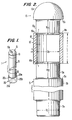
- Fig. 1 illustrates a pivot rod 1 in accordance with a preferred embodiment of the present invention.
- a pivot rod 1 may serve as a push rod of the type finding particular utility in drive trains as described relative to Figs. 3 and 4.
- Pivot rod 1 is comprised of a mounting shaft 5, a pair of attachment sleeves 10, and a pair of pivot inserts 15, 20.
- Each of the pivot inserts 15 is formed of a ceramic material, such as silicon nitride
- the mounting shaft 5 is a metal rod such as a piece of standard steel rod stock or a cast steel piece.
- each of the sleeves 10 may be formed of a piece of "off the shelf" tubing, such as steel tubing of a standard size, tolerances, and wall thickness.
- the mounting shaft 5 of pivot rod 1 has reduced diameter end portions 5a at each of opposite ends of a body portion 5b onto which attachment sleeve 10 is interference fitted.
- a reduced diameter first portion 15a of the pivot insert 15 (or a corresponding reduced diameter portion 20a of pivot insert 20, only a portion of which is visible in Fig. 1) is press fit secured within a receiving space 10' defined by the peripheral wall of attachment sleeve 10, after the attachment sleeve 10 has been secured to mounting shaft 5 for the reasons noted in the following paragraph.
- the thickness t and composition of the attachment sleeve 10, as well as the extent of the interference are selected in accordance with the above-referenced relationships disclosed in EP-A-0 282 714, so as to result in the peripheral wall of attachment sleeve 10 being plastically deformed by the first portion 15a, 20a of the pivot insert 15, 20 and by the end portion 5a of the counting shaft 5 during formation of the interference fits without exceeding the maximum tensile principle stress of the ceramic material of the pivot inserts 15, despite variations in the degree of diametral interference existing between the internal diameter of the peripheral wall circumscribing the receiving space 10' of the attachment sleeve 10 and the external diameter of the first portion 15a of the pivot insert 15 resulting from manufacturing tolerances.
- the combined length composed of the axial length H PI of the first portion 15a, 20a of the respective pivot insert 15, 20 and the axial length H SI of the end portion 5a of the mounting shaft 5 is made to be greater than the axial length L of the attaching sleeve 10 to prevent damage to the brittle ceramic material of the pivot insert 15, 20, both during formation of the joint between it and the mounting shaft 5 and to prevent fracturing during use due to the transmission of axial loads between the pivot insert 15, 20 and the mounting shaft 5 via the attachment sleeve 10.
- the first, (insertion) portion 15a, 20a is joined to a second (pivot surface) portion 15b (which is convexly curved) or 20b (which is provided with a concavely curved recess 20d) via a shoulder 15c, 20c, respectively, to enable the pivot surface to be maximized while achieving the other benefits noted in the following paragraph.
- a shoulder 15c, 20c may be damaged if it were to impact against the facing end surface 10a of the attachment sleeve 10 during creation of the interference fit securement.
- brittle cracking leading to failure of the ceramic pivot insert 15, 20 could be experienced due to overstressing of this shoulder 15c, 20c or the fillet interconnecting it to the first portion 15a, 20a, as could occur if the parts were assembled in a fashion permitting axial loads to be transmitted between the shoulders 5c of the mounting shaft and the respective shoulder 15c, 20c of the pivot insert 15, 20 via the attachment sleeve 10.
- the lengths H PI and H SI may be equal, but are not necessarily so, as they may be varied to make one relatively longer or shorter than the other as best suited to manufacturing considerations, so long as neither portion 5a or 15a, 20a is made so long as to impose bending stresses of an extent great enough to cause failure of the attachment, or so short as to provide an inadequate length for a secure fastening of the attachment sleeve 10 thereto.
- pivot rod 1 which gives the appearance, as much as is possible, of a one-piece rod and does not either increase the maximum diameter of the pivot rod 1 or reduce the diameter of the pivot surfaces (keeping in mind that, in practice, such pivot rods will have to pass through bores of the engine structure with which it is associated as part of an overall drive train).
- the diameter D I of the end portion 5a of the mounting shaft 5 and of the insertion portion 15a, 20a of the ceramic pivot inserts 15, 20 is reduced relative to the outer diameter of body portion 5b of the mounting shaft 5 and of the second portion 15b, 20b of the pivot insert 15 at shoulder 5c, 15c, 20c, by an amount that is coordinated to the thickness t of the attachment sleeve 10 and the extent to which the attachment sleeve 10 is deformed as a result of the interference securements produced so as to result in the attachment sleeve 10 being deformed throughout its axial length to a substantially equal extent and so as to have a deformed outer diameter that is substantially constant and equal to the outer diameter of the second portions 15b of the pivot inserts 15 and body portion 5b of the mounting shaft 5.
- the inner rim 10b of the attachment sleeve 10 is chamfered and a radiused or chamfered peripheral edge r provided on end portion 5a of the mounting shaft 5 and insertion portion 15a, 20a of the pivot inserts 15, 20. In this way, the larger portion to be inserted can be guided into the receiving space of the attachment sleeve 10 which will be enlarged thereby.
- Fig. 3 depicts an engine cylinder head valve drive train wherein ball and socket joints 30 are created at each of opposite ends of the push rod 1 to transmit movement produced by a cam 32 to a valve rocker lever 34 that is used to seat and unseat valves 36 with respect to valve seat inserts 38 via a cross bridge 39.
- this drive train also utilizes a pivot rod 1' wherein only a single pivot insert is provided at one end thereof, this being a convex pivot insert.
- pivot rods 1, 1' in addition to being provided with joints 30 for transmission of force from the cam 32 to the rocker arm 34 via pivot rods 1, 1', ball and socket joints 40 are provided by a further modified pivot rod 1'' that acts between the rocker arm 34 and an injector piston 42.
- This pivot rod 1'' is provided with convex surfaced pivot inserts at each of opposite ends thereof.
- a pivot rod produced in accordance with the foregoing has been found to achieve all of the benefits of significantly increased wear life and the simplification of production associated with a pivot rod as produced in accordance with EP-A-0 282 714 without creating any potential areas for stress failure of the ceramic material of the pivot inserts or of the joint between the inserts and the mounting shaft during use or as a result of operational stresses.
- a pivot rod produced in accordance with the present invention is not prone to stress failure or loosening due to thermal effects.
Landscapes
- Engineering & Computer Science (AREA)
- Mechanical Engineering (AREA)
- General Engineering & Computer Science (AREA)
- Chemical & Material Sciences (AREA)
- Combustion & Propulsion (AREA)
- Valve-Gear Or Valve Arrangements (AREA)
- Fuel-Injection Apparatus (AREA)
- Shafts, Cranks, Connecting Bars, And Related Bearings (AREA)
Claims (9)
- Stößelstange (1) mit einer Befestigungsstange (5), mit einem einen inneren Hohlraum (10') aufweisenden Befestigungsrohr (10) und mit einem aus keramischem, eine maximale Hauptzugspannung aufweisenden Material bestehenden Lagereinsatz (15), wobei der Lagereinsatz (15) ein erstes Teil (15a) und ein zweites Teil (15b) aufweist, das davon axial wegweist und einen größeren Außendurchmesser als das erste Teil (15a) aufweist, wobei das erste Teil (15a) in dem Hohlraum (10') angeordnet ist, um den Lagereinsatz (15) mit dem Befestigungsrohr (10) zu verbinden, ohne daß das zweite Teil (15b) einen direkten Kontakt mit dem Befestigungsrohr (10) aufweist, und wobei ein Endstück (5a) der Befestigungsstange (5) in dem Hohlraum (10') des Befestigungsrohres (10) angeordnet ist, um die Befestigungsstange (5) mit dem Befestigungsrohr (10) zu verbinden, dadurch gekennzeichnet, daß das erste Teil (15a) des Lagereinsatzes (15) mit dem Befestigungsrohr (10) durch eine von dem in dem Hohlraum (10') angeordneten ersten Teil (15a) mit der den Hohlraum (10') begrenzenden Wandung des Befestigungsrohres (10) gebildeten Preßsitzverbindung verbunden ist, wobei diese Preßsitzverbindung durch Koordination der Dicke und Materialzusammensetzung der Wandung mit der maximalen Hauptzugspannung so konstruiert ist, daß die maximale Hauptzugspannung des keramischen Materials nicht überschritten wird, ungeachtet von Schwankungen im Ausmaß der diametralen Paßtoleranz zwischen einem inneren Durchmesser (DA) der den Hohlraum (10') begrenzenden Wandung und einem äußeren Durchmesser des ersten Teils (15a) des Lagereinsatzes (15), die aufgrund von Herstellungstoleranzen der Wandung auftreten, die durch das erste Teil (15a) des Lagereinsatzes (15) während der Bildung der Preßsitzverbindung plastisch verformt worden ist, daß das Endstück (5a) der Befestigungsstange (5) mit dem Befestigungsrohr (10) mit Hilfe einer zweiten Preßsitzverbindung verbunden ist und daß das Endstück (5a) der Befestigungsstange (5) an eine Endfläche des ersten Teils (15a) des Lagereinsatzes (15) anstößt, so daß zur Vermeidung einer Lastübertragung zwischen der Befestigungsstange (5) und dem Lagereinsatz (15) über das Befestigungsrohr (10) der nötige Abstand zwischen dem zweiten Teil (15b) des Lagereinsatzes (15) und dem Befestigungsrohr (10) gewährleistet ist.
- Stößelstange nach Anspruch 1, dadurch gekennzeichnet, daß der Lagereinsatz (15) auf dem zweiten Teil (15b) eine konvex ausgestaltete Kontaktoberfläche aufweist oder daß der Lagereinsatz (15) in dem zweiten Teil (15b) eine konkav ausgestaltete Kontaktoberfläche aufweist.
- Stößelstange nach Anspruch 1 oder 2, dadurch gekennzeichnet, daß an jedem der gegenüberliegenden Enden der Befestigungsstange (5) ein Lagereinsatz (15) mit Hilfe einer Preßsitzverbindung zwischen dem Befestigungsrohr (10) und dem Lagereinsatz (15) befestigt ist.
- Stößelstange nach Anspruch 1, 2 oder 3, dadurch gekennzeichnet, daß das Endstück (5a) der Befestigungsstange (5) einen Außendurchmesser aufweist, der relativ zu dem Außendurchmesser eines Körperteils (5b) der Befestigungsstange (5) um einen Betrag verringert ist, der auf die Dicke des Befestigungsrohres (10) und das Ausmaß der Verformung des Befestigungsrohrs (10) resultierend aus der ersten und zweiten Preßsitzverbindung abgestimmt ist, so daß das Befestigungsrohr (10) über seine Länge einen im wesentlichen konstanten Außendurchmesser aufweist, der gleich groß wie der Außendurchmesser des zweiten Teils (15b) des Lagereinsatzes (15) und des Körperteils (5b) der Befestigungsstange (5) ist.
- Stößelstange nach Anspruch 4, dadurch gekennzeichnet, daß die axiale Länge (HPI) des ersten Teils (15a) des Lagereinsatzes (15) annähernd gleich groß wie die axiale Länge (HSI) des Endteils (5a) der Befestigungsstange (5) ist.
- Verfahren zur Herstellung einer Stößelstange (1) mit einer Befestigungsstange (5) und mit einem aus einem keramischen Material mit einer vorgegebenen maximalen Hauptzugspannung bestehenden Lagereinsatz (15), wobei der Lagereinsatz (15) mit einem ersten Teil (15a) in einem inneren Hohlraum (10') eines Befestigungsrohres (10) angeordnet ist, das an einem Endstück (5a) der Befestigungsstange (5) befestigt ist und wobei ein zweites Teil (15b) des Lagereinsatzes (15) einen Durchmesser größer als das erste Teil (15a) aufweist und axial von dem Hohlraum (10') wegweist, gekennzeichnet durch die Verfahrensschritte:a) Koordination der Dicke und der Materialzusammensetzung der Wandung des Befestigungsrohres (10), die den Hohlraum (10') umschließt, mit der maximalen Hauptzugspannung des keramischen Materials, so daß sich die Wandung unter einer Spannung plastisch verformt, die geringer ist als diese maximale Hauptzugspannung,b) Verbindung des ersten Teils (15a) des Lagereinsatzes (15) mit der Wandung des Befestigungsrohres (10), so daß das zweite Teil (15b) nicht direkt das Befestigungsrohr (10) berührt, mittels einer Preßsitzverbindung und ohne daß die maximale Hauptzugspannung des keramischen Materials über schritten wird, ungeachtet von Schwankungen im Ausmaß der diametralen Paßtoleranz zwischen einem inneren Durchmesser der Wandung und einem äußeren Durchmesser des ersten Teils (15a), die aufgrund von Herstellungstoleranzen der Befestigungsstange (5) und des Lagereinsatzes (15) auftreten, indem eine plastische Verformung der Wandung durch das erste Teil (15a) des Lagereinsatzes (15) während der Bildung der Preßsitzverbindung erzeugt wird, undc) Befestigung des Endstückes (5a) der Befestigungsstange (5) in dem Hohlraum (10') des Befestigungsrohres (10) durch eine Preßsitzverbindung, so daß es an eine Endfläche des ersten Teils (15a) des Lagereinsatzes (15) anstößt,d) so daß der notwendige Abstand zwischen dem zweiten Teil (15b) des Lagereinsatzes (15) und dem Befestigungsrohr (10) sichergestellt ist, um eine Lastübertragung zwischen der Befestigungsstange (5) und dem Lagereinsatz (15) über das Befestigungsrohr (10) zu verhindern.
- Verfahren nach Anspruch 6, dadurch gekennzeichnet, daß Verfahrensschritt (c) vor dem Verfahrensschritt (b) durchgeführt wird, um einen axialen Kontakt zwischen dem zweiten Teil (15b) des Lagereinsatzes (15) und einer gegenüberliegenden Endoberfläche (10a) des Befestigungsrohres (10) zu verhindern, wodurch gewährleistet ist, daß während des Verfahrensschrittes (b) der zweite Teil (15b) nicht beschädigt wird.
- Verfahren nach Anspruch 6 oder 7, dadurch gekennzeichnet, daß die Verfahrensschritte a), b), c) so durchgeführt werden, daß im Ergebnis das Befestigungsrohr (10) über seine axiale Länge im wesentlichen im gleichen Ausmaß verformt wird, so daß es einen verformten äußeren Durchmesser aufweist, der im wesentlichen konstant und gleich groß wie der äußere Durchmesser des zweiten Teils (15b) und vorzugsweise eines Körperteils (5b) der Befestigungsstange (5) ist.
- Verfahren nach Anspruch 6, 7 oder 8, dadurch gekennzeichnet, daß die Verfahrensschritte a), b), c) für jedes der gegenüberliegenden Enden der Befestigungsstange (5) durchgeführt werden.
Applications Claiming Priority (2)
| Application Number | Priority Date | Filing Date | Title |
|---|---|---|---|
| US07/250,069 US4848286A (en) | 1988-09-28 | 1988-09-28 | Ceramic tiped pivot rod and method for its manufacture |
| US250069 | 1988-09-28 |
Publications (2)
| Publication Number | Publication Date |
|---|---|
| EP0361221A1 EP0361221A1 (de) | 1990-04-04 |
| EP0361221B1 true EP0361221B1 (de) | 1994-01-19 |
Family
ID=22946190
Family Applications (1)
| Application Number | Title | Priority Date | Filing Date |
|---|---|---|---|
| EP89117022A Expired - Lifetime EP0361221B1 (de) | 1988-09-28 | 1989-09-14 | Stossstange mit keramischen Lagerenden und deren Herstellungsverfahren |
Country Status (4)
| Country | Link |
|---|---|
| US (1) | US4848286A (de) |
| EP (1) | EP0361221B1 (de) |
| JP (1) | JPH0826762B2 (de) |
| DE (1) | DE68912479T2 (de) |
Families Citing this family (19)
| Publication number | Priority date | Publication date | Assignee | Title |
|---|---|---|---|---|
| JPH02134350U (de) * | 1989-04-12 | 1990-11-07 | ||
| US4966108A (en) * | 1989-04-28 | 1990-10-30 | Cummins Engine Company, Inc. | Sintered ceramic ball and socket joint assembly |
| SE464653B (sv) * | 1989-05-25 | 1991-05-27 | Aelghults Pressverktyg Ab | Stoetstaang hos foerbraenningsmotor samt foerfarande foer dess framstaellning |
| US5168259A (en) * | 1989-09-19 | 1992-12-01 | Semiconductor Energy Laboratory Co., Ltd. | Superconducting coil |
| US5101779A (en) * | 1991-01-15 | 1992-04-07 | Cummins Engine Company, Inc. | Ceramic link |
| US5279211A (en) * | 1992-04-24 | 1994-01-18 | Cummins Engine Company, Inc. | Mechanically retained wear-resistant ceramic pad |
| US5409165A (en) * | 1993-03-19 | 1995-04-25 | Cummins Engine Company, Inc. | Wear resistant fuel injector plunger assembly |
| US5410995A (en) * | 1994-04-15 | 1995-05-02 | Cummins Engine Company, Inc. | Valve crosshead assembly with wear-reducing contact pad |
| US5435286A (en) * | 1994-05-02 | 1995-07-25 | Cummins Engine Company, Inc. | Ball link assembly for vehicle engine drive trains |
| US5899383A (en) * | 1994-05-18 | 1999-05-04 | Cummins Engine Company, Inc. | Ceramic fuel injector timing plunger |
| EP0683314B1 (de) * | 1994-05-18 | 1999-12-15 | Cummins Engine Company, Inc. | Kraftstoffdruckerzeugende Kolbenanordnung für eine druckgezündete Brennkraftmaschine |
| US5542315A (en) * | 1994-06-21 | 1996-08-06 | Cummins Engine Company, Inc. | Elephant's foot adjusting screw assembly for internal combustion engine |
| US5720246A (en) * | 1996-07-23 | 1998-02-24 | Minnesota Mining And Manufacturing | Continuous fiber reinforced aluminum matrix composite pushrod |
| US5890413A (en) * | 1997-01-08 | 1999-04-06 | Generac Portable Products, Llc | Piston for water pump and related method |
| US5996226A (en) * | 1997-12-23 | 1999-12-07 | Itt Manufacturing Enterprises, Inc. | Method of manufacturing push rod balls |
| US7033156B2 (en) * | 2002-04-11 | 2006-04-25 | Luka Gakovic | Ceramic center pin for compaction tooling and method for making same |
| US8312612B2 (en) * | 2002-04-11 | 2012-11-20 | Blue Sky Vision Partners, Llc | Refurbished punch tip and method for manufacture and refurbishing |
| US6854436B1 (en) | 2003-07-25 | 2005-02-15 | Performance Composites Inc | Composite push rod |
| GB201014059D0 (en) * | 2010-08-24 | 2010-10-06 | Element Six Production Pty Ltd | Wear part |
Family Cites Families (11)
| Publication number | Priority date | Publication date | Assignee | Title |
|---|---|---|---|---|
| US2434080A (en) * | 1945-11-05 | 1948-01-06 | Leonard J Rosa | Push rod |
| US2960080A (en) * | 1958-10-29 | 1960-11-15 | Bundy Tubing Co | Push rod and method of its manufacture |
| SU742612A1 (ru) * | 1978-04-03 | 1980-06-25 | Производственное Объединение "Автодизель" | Штанга толкател |
| JPS5546025A (en) * | 1978-09-26 | 1980-03-31 | Usui Internatl Ind Co Ltd | Improved valve push rod for internal combustion engine |
| JPS55146211A (en) * | 1979-05-02 | 1980-11-14 | Usui Internatl Ind Co Ltd | Manufacture of push rod for driving valve of internal combustion engine |
| JPS5713204A (en) * | 1980-06-30 | 1982-01-23 | Isuzu Motors Ltd | Push rod |
| JPS5713203A (en) * | 1980-06-30 | 1982-01-23 | Isuzu Motors Ltd | Push rod |
| US4453505A (en) * | 1982-06-11 | 1984-06-12 | Standard Oil Company (Indiana) | Composite push rod and process |
| EP0133192A1 (de) * | 1983-08-05 | 1985-02-20 | Chrysler Corporation | Ventilstössel mit keramischer Nockenfläche und impulsmagnetischen Druckformungsverfahren |
| JPS62150013A (ja) * | 1985-12-25 | 1987-07-04 | Toshiba Corp | 摺動部材および摺動構体 |
| US4794894A (en) * | 1987-03-05 | 1989-01-03 | Cummins Engine Company, Inc. | Ceramic tipped pivot rod and method for its manufacture |
-
1988
- 1988-09-28 US US07/250,069 patent/US4848286A/en not_active Expired - Lifetime
-
1989
- 1989-09-14 EP EP89117022A patent/EP0361221B1/de not_active Expired - Lifetime
- 1989-09-14 DE DE89117022T patent/DE68912479T2/de not_active Expired - Fee Related
- 1989-09-21 JP JP1246219A patent/JPH0826762B2/ja not_active Expired - Lifetime
Also Published As
| Publication number | Publication date |
|---|---|
| JPH02185606A (ja) | 1990-07-20 |
| US4848286A (en) | 1989-07-18 |
| DE68912479D1 (de) | 1994-03-03 |
| DE68912479T2 (de) | 1994-05-11 |
| EP0361221A1 (de) | 1990-04-04 |
| JPH0826762B2 (ja) | 1996-03-21 |
Similar Documents
| Publication | Publication Date | Title |
|---|---|---|
| EP0361221B1 (de) | Stossstange mit keramischen Lagerenden und deren Herstellungsverfahren | |
| EP0282714B1 (de) | Stossstange mit keramischen Lagerenden und deren Herstellungsverfahren | |
| EP0682178B1 (de) | Verbindung durch Kugeln für Antriebsanordnungen von Fahrzeugmotoren | |
| EP0170378B1 (de) | Nockenwelle für Verbrennungsmotor | |
| EP0677656B1 (de) | Offendüsenkraftstoffeinspritzeinrichtung mit einem verschleissfesten Einspritzkolbenzusammenbau | |
| US4674453A (en) | Rocker arm and method of forming the same | |
| JP3995075B2 (ja) | 内燃機関用の燃料噴射システムのための燃料高圧アキュムレータ | |
| CA1061667A (en) | Ductile iron roller tappet body and method for making same | |
| EP0279275A1 (de) | Kugelgelenk aus Keramik | |
| EP0907034A3 (de) | Mehrzylinder-Scheibenbremse | |
| CA1319332C (en) | Composite brake drum | |
| US5284112A (en) | Valve operating mechanism including valve lifter | |
| US4796517A (en) | Metal piston and ceramic piston pin assembly | |
| EP0682171A2 (de) | Ventiljoch mit einer den Verschleiss verringenden Kontaktfläche | |
| EP0896130A3 (de) | Al oder Al-Legierung-Hubventil und Verfahren zu seiner Herstellung | |
| EP1227269A2 (de) | Kolbenbolzen für eine Brennkraftmaschine | |
| US5269268A (en) | Tappet in an internal combustion engine and method of manufacturing the same | |
| US5327814A (en) | Mechanical assemblies and methods of making same | |
| CN2781000Y (zh) | 单缸四冲程汽油机用凸轮轴组件 | |
| CN2237749Y (zh) | 车用钢基涂层同步器 | |
| US5809842A (en) | Ceramic sliding component | |
| EP0618350B1 (de) | Tassenstössel in einer Brennkraftmaschine und Verfahren zur Herstellung | |
| JPH06137120A (ja) | 内燃機関用バルブ | |
| US6341587B1 (en) | Lever-type cam follower for a valve train of an internal combustion engine | |
| JPH01259157A (ja) | エンジン部品の耐摩耗性向上方法及び同方法により作られたエンジン部品 |
Legal Events
| Date | Code | Title | Description |
|---|---|---|---|
| PUAI | Public reference made under article 153(3) epc to a published international application that has entered the european phase |
Free format text: ORIGINAL CODE: 0009012 |
|
| AK | Designated contracting states |
Kind code of ref document: A1 Designated state(s): DE FR GB IT SE |
|
| 17P | Request for examination filed |
Effective date: 19900901 |
|
| 17Q | First examination report despatched |
Effective date: 19911121 |
|
| GRAA | (expected) grant |
Free format text: ORIGINAL CODE: 0009210 |
|
| AK | Designated contracting states |
Kind code of ref document: B1 Designated state(s): DE FR GB IT SE |
|
| REF | Corresponds to: |
Ref document number: 68912479 Country of ref document: DE Date of ref document: 19940303 |
|
| ET | Fr: translation filed | ||
| ITF | It: translation for a ep patent filed | ||
| PLBE | No opposition filed within time limit |
Free format text: ORIGINAL CODE: 0009261 |
|
| STAA | Information on the status of an ep patent application or granted ep patent |
Free format text: STATUS: NO OPPOSITION FILED WITHIN TIME LIMIT |
|
| 26N | No opposition filed | ||
| EAL | Se: european patent in force in sweden |
Ref document number: 89117022.7 |
|
| PGFP | Annual fee paid to national office [announced via postgrant information from national office to epo] |
Ref country code: SE Payment date: 19950811 Year of fee payment: 7 Ref country code: FR Payment date: 19950811 Year of fee payment: 7 |
|
| PGFP | Annual fee paid to national office [announced via postgrant information from national office to epo] |
Ref country code: DE Payment date: 19950818 Year of fee payment: 7 |
|
| PGFP | Annual fee paid to national office [announced via postgrant information from national office to epo] |
Ref country code: GB Payment date: 19950825 Year of fee payment: 7 |
|
| PG25 | Lapsed in a contracting state [announced via postgrant information from national office to epo] |
Ref country code: GB Effective date: 19960914 |
|
| PG25 | Lapsed in a contracting state [announced via postgrant information from national office to epo] |
Ref country code: SE Effective date: 19960915 |
|
| PG25 | Lapsed in a contracting state [announced via postgrant information from national office to epo] |
Ref country code: FR Effective date: 19960930 |
|
| GBPC | Gb: european patent ceased through non-payment of renewal fee |
Effective date: 19960914 |
|
| PG25 | Lapsed in a contracting state [announced via postgrant information from national office to epo] |
Ref country code: DE Effective date: 19970603 |
|
| EUG | Se: european patent has lapsed |
Ref document number: 89117022.7 |
|
| REG | Reference to a national code |
Ref country code: FR Ref legal event code: ST |
|
| REG | Reference to a national code |
Ref country code: FR Ref legal event code: ST |
|
| PG25 | Lapsed in a contracting state [announced via postgrant information from national office to epo] |
Ref country code: IT Free format text: LAPSE BECAUSE OF NON-PAYMENT OF DUE FEES;WARNING: LAPSES OF ITALIAN PATENTS WITH EFFECTIVE DATE BEFORE 2007 MAY HAVE OCCURRED AT ANY TIME BEFORE 2007. THE CORRECT EFFECTIVE DATE MAY BE DIFFERENT FROM THE ONE RECORDED. Effective date: 20050914 |