EP0361222B1 - Automatisches Servo-Verstärkungs-Kalibriersystem für einen Plattenspeicher - Google Patents
Automatisches Servo-Verstärkungs-Kalibriersystem für einen Plattenspeicher Download PDFInfo
- Publication number
- EP0361222B1 EP0361222B1 EP89117036A EP89117036A EP0361222B1 EP 0361222 B1 EP0361222 B1 EP 0361222B1 EP 89117036 A EP89117036 A EP 89117036A EP 89117036 A EP89117036 A EP 89117036A EP 0361222 B1 EP0361222 B1 EP 0361222B1
- Authority
- EP
- European Patent Office
- Prior art keywords
- track
- servo
- signal
- gain
- position detector
- Prior art date
- Legal status (The legal status is an assumption and is not a legal conclusion. Google has not performed a legal analysis and makes no representation as to the accuracy of the status listed.)
- Expired - Lifetime
Links
- 238000012937 correction Methods 0.000 claims abstract description 51
- 238000000034 method Methods 0.000 claims abstract description 24
- 238000012545 processing Methods 0.000 claims abstract description 9
- 230000008859 change Effects 0.000 description 7
- 230000007246 mechanism Effects 0.000 description 7
- 230000006870 function Effects 0.000 description 4
- 230000010354 integration Effects 0.000 description 4
- 238000004519 manufacturing process Methods 0.000 description 3
- 238000001514 detection method Methods 0.000 description 2
- 238000010586 diagram Methods 0.000 description 2
- 238000005516 engineering process Methods 0.000 description 2
- 230000008569 process Effects 0.000 description 2
- 238000004364 calculation method Methods 0.000 description 1
- 230000008878 coupling Effects 0.000 description 1
- 238000010168 coupling process Methods 0.000 description 1
- 238000005859 coupling reaction Methods 0.000 description 1
- 238000011161 development Methods 0.000 description 1
- 230000018109 developmental process Effects 0.000 description 1
- 238000006073 displacement reaction Methods 0.000 description 1
- 230000007274 generation of a signal involved in cell-cell signaling Effects 0.000 description 1
- 238000005259 measurement Methods 0.000 description 1
- 230000004044 response Effects 0.000 description 1
Images


Classifications
-
- G—PHYSICS
- G11—INFORMATION STORAGE
- G11B—INFORMATION STORAGE BASED ON RELATIVE MOVEMENT BETWEEN RECORD CARRIER AND TRANSDUCER
- G11B5/00—Recording by magnetisation or demagnetisation of a record carrier; Reproducing by magnetic means; Record carriers therefor
- G11B5/48—Disposition or mounting of heads or head supports relative to record carriers ; arrangements of heads, e.g. for scanning the record carrier to increase the relative speed
- G11B5/54—Disposition or mounting of heads or head supports relative to record carriers ; arrangements of heads, e.g. for scanning the record carrier to increase the relative speed with provision for moving the head into or out of its operative position or across tracks
- G11B5/55—Track change, selection or acquisition by displacement of the head
- G11B5/5521—Track change, selection or acquisition by displacement of the head across disk tracks
- G11B5/5526—Control therefor; circuits, track configurations or relative disposition of servo-information transducers and servo-information tracks for control thereof
- G11B5/553—Details
- G11B5/5534—Initialisation, calibration, e.g. cylinder "set-up"
Definitions
- the invention is directed to a method and a system for automatically calibrating gain parameters of a servo control of a computer disk drive in accordance with the precharacterizing parts of the independent claims 1 and 7, respectively.
- Such a method and system are known from IBM TDB Vol. 23, No.1, June 1980, pages 304-305.
- a read/write head is positioned over a preselected track while the disk is rotated to encode and/or decode a sequence of magnetic states into each sector of the track directly beneath the head. In this manner, data may be either written onto the disk or read from the disk as a function of the sequence of magnetic states, as is well known.
- the width of the head is approximately equal to the width of a track. It is critical that the head be precisely aligned with the centerline of the track being written to or read from to make certain that correct data information is being stored onto or read from the magnetic disk.
- the head In the event that the head is not properly aligned with a track centerline, the head will straddle two adjacent tracks and encode or decode invalid data information onto or from the two overlapped tracks.
- a plurality of disks are stacked on a common rotating shaft in an axially spaced relation to one another and a rotable arm mounting at least one head at an outer end is positioned over each of the rotating disks.
- An electromechanical device such as a dc limited angle motor and voice coil type actuator, is coupled to the arms.
- the dc limited angle motor moves the arms to position and holds the heads over the respective disks at a preselected angle such that the heads are each aligned with the centerline of a particular track of a respective disk.
- one head at a time is operated to encode or decode its respective disk.
- the density of the data stored on the disks is very high resulting in extremely minimal dimensions for the width of each track. Accordingly, it is extemely important that the control mechanism for the limited angle motor operates to precisely control the angular position of the mounted head to coincide with the centerline of a track.
- a servo mechanism generally comprises a control mechanism for a dervice wherein an error signal derived from a summation of a reference input and an actual output is fed back to the control mechanism to correct the performance of the controlled device.
- the actual angular position of a head is summed with the desired angular position for the arm mounting the head and the difference is utilized to control the limited angle motor to move the head to the correct angular position.
- the limited angle motor is energized to change the angular orientation of an arm until the actual angular position of the head equals the desired angular position, i.e., the error signal is zero.
- position information relating to the head is embedded or written directly on the tracks of each disk between the data fields of adjacent sectors.
- the head reads the position information as the disk is rotated beneath the head and transmits the embedded information to a track position detector for processing. Accordingly, the head serves as a position transducer component for the servo mechanism.
- the embedded position information includes A and B bursts encoded on the track adjacent the beginning of each data field. For each data field, one of the bursts is positioned at and above the track centerline and the other burst is spaced in the circumferential direction from the first burst and positioned at and below the track centerline, or vice versa.
- Each burst comprises a sequence of pulses and the track position detector integrates the signals of the A and B bursts over time to provide integrated A - B and A + B analog signals.
- the output of the track position detector is defined as A-B/A+B.
- the integration value for each of the A and B bursts should approximately equal one another and A-B/A+B should equal zero.
- the A-B/A+B ratio is a proportionality number representative of a unit of measure of track position from the centerline.
- the AB bursts are position references which permit the head to relate position error from centerline of the track.
- the AB bursts are encoded on the disks by a servo writer which utilized an external transducer such as a laser interferometer to precisely position the servo writer head relative to the centerline.
- the servo writer does not write the AB bursts exactly on the centerline.
- the servo writer positions itself over the centerline of the track by the interferometer and measures any misplacements of the AB bursts from the centerline caused by the disturbances during the writing of the AB bursts.
- the measurement information is recorded in each sector of the track adjacent the actual AB bursts as a Servo Correction Number.
- the Servo Correction Number is read by the head during normal operation of the disk drive and is provided to the servo control system to compensate for any off center readings of the AB bursts caused by misplacements which occurred during the servo writer operation.
- a significant problem associated with the embedded servo technology described above is that the system requires a tight control over the track position detector gain and servo control feedback loop gain for satisfactory performance. This is particularly true when the data is stored on the disks in a high density configuration which requires a very precise, high performance control of head position and also, when the disk drive components are mass-produced with normal manufacturing tolerances.
- IBM TDB, Vol 23, No. 1, June 1980, pages 304-305 discloses a servo system for a disk memory drive which uses a servo pattern of pure sine waves recorded at frequencies f1 und f2.
- each track is divided down the middle with one half containing f1 signals and the other half containing f2 signals, with f1 and f2 signals switching sides on the track at regular intervals to form a pattern looking like an elongated checkerboard.
- a control signal is then used to switch back and forth between two states as the boundaries in the checkerboard pattern rotate past the head.
- This control signal is used to control the direction of the corrective force applied to the head in response to the difference in amplitude of the f1 and f2 signals such that the shift of the head from center of the track while writing due to the unequal enhancement of the f1 and f2 signals will alternate in direction at the same rate that the control signal switches states.
- EP-A-0 247 339 describes a servo gain control system for use in a disk memory drive. Compensation for servo gain variations when the disk memory drive is connected to different magnetic heads is achieved by determining individual servo gain corrections for each magnetic head at serveral different selected tracks on the associated memory disk, by storing the individual servo gain corrections and by addressing a stored individual servo gain correction for each selected magnetic head for coupling to the servo to equalize servo gain when positioning each selected magnetic head at a selected track.
- US-A-4 642 541 describes a technique for determining the noise-free value of a system parameter, e.g., the head position in a disk drive which is time variable and has a noise component.
- the described technique includes securing a pair of first values, V a and V b by detecting motor current sense voltage, integrating it with respect to time and passing the result through a pair of second order filters.
- a third value V c is also secured by detecting head position error in the usual manner and then passing it through a second order low-pass filter.
- the position error signal value V c is then summed with the first two values V a and V b to secure a relatively noise-free position error signal. It is a primary object of the present invention to provide an automatic track position detector and loop gain calibration system to accurately calibrate the servo system gain parameters for optimized, high performance operation.
- a method for automatically calibrating gain parameters of a servo control for a computer disk drive device having at least one disk surface, the servo control including embedded servo position information equally spaced from the track centerline and a track position detector using said servo information and deriving a head positioning control signal therefrom is characterized by comprising the steps of: encoding, as said servo position information, a series of AB bursts on each data track, each A burst being located on one side of said track centerline, said A burst followed by a B burst being located on the respective other side of the track centerline; encoding servo correction number information on each track adjacent to said AB burst representative of misplacements of said AB burst pattern from said track centerline; encoding a series of AB bursts on a calibration track on said one disk surface of the disk drive device, said AB bursts being intentionally displaced from said track centerline in accordance with a known off-center pattern being
- a system for automatically calibrating gain parameters of a servo control for a computer disk drive device having a plurality of disk surfaces the servo control including embedded servo position information equally spaced from the track centerline and a track position detector for receiving the servo position information and producing an output signal derived from the servo position information
- the embedded servo position information includes a series of AB bursts equally spaced from the track centerline, each A burst followed by a B burst being located on the respective other side of the track centerline, the embedded servo position information further including a servo correction number, located on each data track adjacent to said AB burst, representative of misplacements of said AB burst pattern from said track centerline;
- a TPDCAL signal generator is coupled to an output of the track position detector to adjust the magnitude of the track position detector output signal; and a calibration track is provided on the one of the disk surfaces of the computer disk drive device, the calibration track including embedded servo position information
- the invention provides calibration of both the track position detector gain and overall servo control loop gain. Variations in the head width and read channel electronics cause different and erroneous track position detector gains. Moreover, variations in servo loop control electronics and mechanical components of the disk drive can result in a overall servo loop gain variation which is unacceptable. These loop gain variations are due to manufacturing tolerances independent of the track position detector gain. Calibration of the track position detector gain and the overall servo control loop gain is necessary to eliminate gain errors caused by varying head dimensions, manufacturing tolerances, etc. to thereby ensure high performance servo control and to maintain servo stability.
- proper track position detector gain is calibrated by utilizing the AB bursts and servo correction number information embedded in a special calibration track written on each disk surface. More specifically, at least one track on each disk surface of the disk drive is reserved for calibration purposes.
- the placement of the AB bursts on the calibration track is intentionally displaced from the centerline in accordance with a known pattern, e.g. a 760 Hz asymetric square wave.
- the servo correction numbers for the calibration track are determined and embedded between data fields of the calibration track so as to correct the 760 Hz square wave distortion of the AB burst placement.
- the calibration is initiated by a head tracking one of the special servo written calibration tracks.
- the head reads the AB bursts and the track position detector processes the AB burst signals, as will be described in more detail in the following Detailed Description section, to provide a "raw" track position signal corresponding to the misplaced AB bursts, as encoded by the servo writer.
- the "raw" position signal is summed with the servo correction numbers for the calibration track to correct the off center readings provided by the AB bursts.
- the entire displacement indicated by the head reading of the AB bursts is the intended servo writer disturbance of the AB positions on the calibration track.
- a significant aspect of the track position detector gain calibration system of the present invention is the recognition that the servo correction number information is equal and opposite to the raw position information for the calibration track when the gain of the track position detector is properly calibrated.
- any residual 760 Hz square wave signal remaining after the summation of the servo correction numbers and the raw position information would be attributable to factors relating to an incorrect track position detector gain.
- a digital signal processing technique such as a discrete Fourier transform, is applied to the signal derived from the summation of the servo correction number and raw position information to detect a residual signal at the 760 Hz disturbance frequency.
- a convergence algorithm operates through iterations, i.e., after a raw position information and servo correction number summation for all sectors of the calibration track being tracked by the head, to minimize the 760 Hz component of the summation of the raw position information and the servo correction number. More specifically, in a preferred embodiment of the invention, a microprocessor in the servo control system performs the discrete Fourier transform for an average of the summation determined during traversal of all the sectors of the calibration track by the head during several revolutions of the disk to detect any residual 760 Hz disturbance signal.
- the microprocessor then operates to adjust the gain of the track position detector to tend to minimize the 760 Hz residual signal and repeats the digital signal processing and gain adjustment in iterations during successive revolutions of the disk until the 760 Hz component of the summation average is minimized.
- the gain of the track position detector will be optimized for AB burst and servo correction number position reference processing.
- the gain of the overall servo control loop is automatically calibrated for optimized performance of the servo control by measuring and compensating for system gain errors at a frequency which is representative of the servo bandwidth of the disk drive.
- This disturbance frequency is determined experimentally for the disk drive system. For example, in a prototype disk drive embodying the present invention, the desired servo bandwidth was found to be 330 Hz.
- the microprocessor performs a single frequency Bode plot at the determined servo bandwidth and adjusts the overall loop gain through iterations until the gain of the loop at the servo bandwidth frequency, as determined in a Bode plot, is 1 (0 dB in the Bode plot).
- a digital sine wave signal having a frequency equal to the servo bandwidth, e.g.
- the Bode plot and gain adjustment is performed by the microprocessor after the result of the discrete Fourier transform without the 330 Hz signal is complexly subtracted from the result of the discrete Fourier transform with the 330 Hz sine signal applied to the summing junction, as determined during that iteration.
- the value of the adjustment to the overall loop gain is adjusted, once each iteration, as a function of the ratio of the summing junction output over the summing junction input at 330 Hz after the complex subtraction, until the adjustment value of an iteration equals the adjustment value of the previous iteration.
- the loop gain determination at the summing junction will be a proper loop gain for the overall system when the two adjustment values are equal. More specifically, the Bode plot will have a 0 dB gain at 330 Hz.
- the automatic track position detector gain calibration and automatic overall control loop gain calibration are performed in conjunction with one another in respect of a disk drive including a plurality of disks with a different head for each disk surface, as described above, to improve the speed of operation of the calibration system.
- the track position detector gain may be erroneous due to the particular head operating at any one time.
- the performance of the track position detector gain calibration is a relatively slow operation, (i.e., it takes a relatively long time to converge on a minimized 760 Hz residual signal), it is generally preferable to measure and calibrate the overall loop gain.
- the only difference in the servo loop gain as between different disk surfaces is the different heads with all of the other components of the control loop being common to the control of all of the disks. Accordingly, the automatic calibration of the track position detector gain is performed for only one of the heads. Thereafter, the overall loop calibration system is used to calibrate the loop gain for the remaining disk surfaces and their heads with only the gain of the track position detector being adjusted to obtain a 0 dB gain at the 330 Hz frequency.
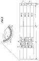
- Fig. 1 is an exploded perspective view of a disk drive system.
- Fig. 2 is a detailed illustration of a disk surface including an enlarged view of one portion of a track of the disk.
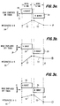
- Figs. 3 a, b, c are graphic illustrations of a head position determination in an embedded servo control system.
- Figs. 4 a, b each illustrate servowritten AB bursts in an embedded disk.
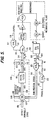
- Fig. 5 is a block diagram of a servo control loop including the automatic gain calibration system of the invention.
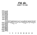
- Figs. 6 a, b, c are graphs illustrating 760 Hz signals for high, low and correct track position detector gains.
- Figs. 7 a, b are graphs illustrating the combined track position detector gain and loop gain calibration of the invention for a multiple disk drive system.
- FIG. 1 an exploded perspective view of a disk drive system.
- the system 10 is contained in a chassis 19.
- the components of the system 10 sit in a lower housing 18.
- the lower housing 18 components comprise three disks 12, a dc limited angle motor 14, a voice coil type actuator 15, at least three heads 13, three arms 20, a flex cable 16 and a cap 17.
- the lower housing 18 is covered by a cover plate 11 and sits in the chassis 19.
- Fig. 1 depicts a disk drive system with three disks
- a typical disk drive system may contain, for example, eight disks.
- the disks 12 are stacked on a common rotating shaft in an axially spaced relation to one another.
- the dc limited angle motor 14 and voice coil type actuator 15 are coupled to the arms 20.
- the heads 13 are also coupled to the arms 20.
- the motor 14 and actuator 15 control the position and hold each of the heads 13 over a respective disk 12.
- the precise control of the limited angle motor 14 is accomplished by a signal applied to the flex cable 16 from a servo control as will be described.
- This flex cable 16 couples the dc limited angle motor 14 to the servo control.
- FIG. 2 there is illustrated a detailed view of a disk surface including an enlarged view of one section of the disk.
- Each disk is divided into adjacent circumferential tracks.
- the tracks are further divided into sectors.
- Fig. 2 depicts a cross section of a disk 24 with the track and sectors shown. Further, an enlarged portion of the disk is shown to illustrate the individual sectors 23 of several adjacent tracks 22.
- the information contained in each sector can be divided into three groups.
- First is the header 25 which contains such information as the servo correction number (SCN) 26 as described above.
- Second is the data field 27 which contains, for example, 512 bytes of data.
- the last field 28 contains such information as the error correction code used for error detection.
- the AB bursts 50 are also positioned in the header of each sector, as illustrated.
- Fig. 3(a) - (c) are graphic illustrations of a head position determination in an embedded servo control system of the type depicted in Fig. 2. Each figure depicts the head 31 in different positions with respect to the centerline of the track. Also illustrated are the resulting waveforms from the integration of the A 29 and B 30 burst signals over time.
- the embedded position information relating to the head includes A 29 and B 30 bursts encoded on the track. For each data field as shown in the figures, one burst is positioned at and above the track centerline and the other burst is at and below the track centerline.
- the head 31 is centered on the centerline of the track. As the head travels across the track, the system integrates over time resulting in the waveform 34. Thus, when A 29 and B 30 burst are integrated over time by the servo control system, the resulting waveforms 32 and 33 respectively, indicate a summed integration value of zero. This means that the head 31 is properly positioned over the centerline of the track.
- the head 31 is displaced above the centerline of the track.
- the integrated A-B waveform 35 shows A burst integrated curve 32 more positive than the B burst integrated curve 33.
- the resulting summed integrated value is a positive number which indicates that the head is above the centerline of the track.
- the head 31 is displaced below the centerline of the track.
- the system calculates the integrated A-B value resulting in the waveform 36.
- the B burst integrated curve 33 results in a more negative value than the A burst integrated curve 32. The sum, therefore, is negative indicating that the head 31 is below the centerline of the track.
- Figs. 4(a)-(b) illustrate servo written AB bursts in an embedded disk.
- Fig. 4(a) illustrates the head 37 in position over the centerline 40 of a track.
- the AB burst placement is in a normal pattern of an A burst immediately below the centerline 40 and a B burst immediately after the A burst and above the centerline 40.
- the resulting raw position signal 38 (the integration value of A-B) is a straight line waveform indicating the correct positioning of the head 37.
- Fig. 4(b) depicts the placement of the AB bursts as written in a special calibration track of each disk surface in accordance with the invention.
- the head 37 is positioned over the centerline 40 of the track.
- the AB bursts are not placed symmetrically with respect to the centerline 40. Instead, they are placed asymmetrically to the centerline 40, for example, in accordance with a 760 Hz asymmetric square wave.
- the resulting raw position signal which is read by the head 37 will be an asymmetrical square wave 39 indicating the raw position error of the head 37.
- the head 37 While the head 37 is reading this signal, it is also reading the servo correction numbers for the calibration track sectors.
- the resulting servo correction number waveform for the calibration track should be the inverse of the raw position signal 39.
- the two signals are summed to obtain the proper position information.
- the result of the summation will be a corrected position signal similar to the raw position signal depicted in Fig. 4(a).
- a servo control system for controlling the coil actuator and dc limited angle motor to precisely position the heads over the tracks of the disks.
- the heads of the electromechanical system 100 (which includes the voice coil actuator, limited angle dc motor, arms and heads, as described above) are all coupled to an output line 101 to transmit AB bursts, decoded by an operating head, to a track position detector 102.
- the track position detector 102 integrates each of the A and B sets of pulses to obtain A and B position values.
- the track position detector 102 then calculates A1-B and A+B values.
- a signal representing A-B is output on line 103 and a signal representing A+B is output on line 104.
- the line 103 is coupled to an input of an analog-to-digital converter 105 and the line 104 is coupled to a reference port of the analog-to-digital converter 105.
- the analog-to-digital converter 105 will output a digital signal on line 106 which is representative of the ratio A-B/A+B.
- the ratio A-B/A+B is the track position detector output. This ratio provides the raw position error information of an operating head relative to the centerline of a track of the corresponding disk.
- the analog-to-digital converter 105 is preferably an 8-bit converter such that the digital signal for track width is 512 counts per track. If the track position detector is properly calibrated, the raw position error information will be an indication of position from centerline in proportion to a 512 count per track digital signal.
- the line 106 is coupled to a summing junction 107 of a microprocessor 200.
- a line 108 is also coupled to the summing junction 107 to input the servo correction number decoded by the operating head to correct the raw position information such that the output (e(n)) of the summing junction 107 on line 109 indicates a corrected digital count relative to the track centerline.
- a line 150 is also coupled to the summing junction 107 to input offset from centerline information. Ordinarily, the offset from centerline is zero since it is the objective of the system to position the heads over a centerline.
- the line 109 is coupled to an input of a digital filter 110 of the microprocessr 200 which provides an output signal c(n) on line 111 suitable for control of the coil actuator. More specifically, e(n) represents the "error" between the actual position of the head determined from the embedded servo information decoded by the operating head, and the desired position, i.e., the digital count representing the track centerline (the offset input on line 150) and c(n) is a correction based on e(n).
- the line 111 is coupled to a summing junction 112 also in the microprocessor 200.
- the output (DA o (n)) of the summing junction 112 is input via line 114 to a digital-to-analog converter 115.
- the digital-to-analog converter 115 converts the digital count (DA o (n)) representing the correction of the head relative to the track centerline to an analog signal for controlling the coil actuator of the dc limited angle motor as is known.
- the analog output of the digital-to-analog converter 115 is input to a power amplifier 116 which, in turn, drives the coil actuator to correctly position the operating head over the track centerline.
- a digital-to-analog converter 117 is coupled to a reference port of the digital-to analog converter 115 by a line 118 such that the analog output of the digital-to-analog converter 117 operates to adjust the analog output of the digital-to-analog converter 115 as a function of the output of the digital-to-analog converter 117.
- the overall gain of the control loop defined by the components illustrated in Fig. 5, can be adjusted and thereby calibrated.
- a LOOPCAL signal is input to the digital-to-analog converter 115 on line 119 to set the amount of adjustment of the overall loop gain, as will be described below.
- a digital-to-analog converter 120 is coupled to the reference port of the analog-to-digital converter 105 via the line 104 by means of a line 121.
- the analog output of the digital-to-analog converter 120 is summed with the analog A+B value calculated by the track position detector 102 and thereby affects the track position detector gain.
- the digital-to-analog converter 120 is operable to adjust the gain of the track position detector 102 by a TPDCAL signal.
- the TPDCAL signal is input on a line 122 coupled to the input of the digital-to-analog converter 120.
- Both the LOOPCAL and TPDCAL signals are generated by the the microprocessor 200 in accordance with the invention to automatically calibrate the overall loop gain and the track position detector gain.
- the microprocessor 200 performs a convergance algorithm through iterations, one iteration per twenty five averaged revolutions of the disk surface being read, to minimize the 760 Hz component of the c(n) signal.
- the track position detector gain is correct when the 760 Hz component of c(n) is minimal.
- the microprocessor 200 After the operating head decodes the AB burst and servo correction number information embedded on the sectors of the calibration track and the digital filter 110 calculates c(n), the microprocessor 200 performs a digital signal processing technique, such as a discrete Fourier transform at 760 Hz, on an average of twenty five revolutions of the c(n) signal. The microprocessor 200 then generates a digital signal (TPDCAL) based on the phase of the residual 760 Hz component determined through the discrete Fourier transform.
- a digital signal processing technique such as a discrete Fourier transform at 760 Hz
- Figs. 6 (a)-(c) there is illustrated, in graph form, typical residual signals at 760 Hz when the gain of the track position detector 102 is high, low and correct, respectively.
- the 760 Hz signal when the track position detector gain is low, is 180° out of phase with the 760 Hz signal which occurs when the track position detector gain is high.
- the 760 Hz signal is zero when the gain for the track position detector 102 is correct.
- some residual 760 Hz signal always remains and the microprocessor 200 seeks to minimize the 760 Hz signal, as illustrated in Fig. 6(c).
- the phase of the 760 Hz signal indicates to the microprocessor 200 whether the gain of the track position detector 102 is too high or too low and the microprocessor 200 generates a TPDCAL signal acting to raise or lower the track position detector gain as a function of the phase of the 760 Hz residual signal determined through the discrete Fourier transform.
- the track position detector gain is very non-linear and a known change in the A-B/A+B ratio will not result from a known TPDCAL signal.
- the microprocessor 200 merely generates a TPDCAL signal at a certain digital count which will tend to either increase or decrease the gain via the digital-to-analog converter 120, depending on the phase of the 760 Hz signal.
- the microprocessor 200 repeats the discrete Fourier transform and TPDCAL signal generation, in iterations, for successive groups of twenty five averaged revolutions until the phase of the 760 Hz component of c(n) changes sign, indicating that the gain has gone from too high to too low or vice versa. After a phase change on the 760 Hz signal, the microprocessor 200 changes the direction of gain adjustment through the digital-to-analog converter 120 by a second smaller digital count, as the amplitude of the 760 Hz signal is now close to zero, and continues the iterations to converge on a minimal 760 Hz signal.
- the 760 Hz signal is of a preselected minimal amount, as illustrated in, for example, Fig.
- the calibration is complete and the gain of the track position is properly calibrated.
- the microprocessor 200 will increment the adjustment to track position detector gain by 10 digital counts per iteration until a sign change in the 760 Hz component is detected. The microprocessor 200 will then increment by one digital count in the opposite direction until another sign change is detected.
- the calibration is complete inasmsuch as a sign change with one digital count incremental adjustment to the gain of the track position detector via the digital-to-analog converter 120 indicates that the 760 Hz component is close to zero.
- the microprocessor 200 seeks a Bode plot of loop gain in dB versus frequency such that the open loop gain of the system, i.e. c(w)/DA o (w), equals one at 330 Hz (the desired frequency bandwidth, as discussed above).
- the microprocessor 200 performs a single frequency discrete Fourier transform at 330 Hz of twenty five averaged revolutions of each of c(n) and DA o (n).
- the microprocessor 200 repeats the discrete Fourier transform at 330 Hz of each of c(n) and DA o (n) with a known 330 Hz sine wave signal introduced into the system, in the example through a line 113 at the summing junction 112.
- the microprocessor 200 continues the calculations through iterations, one per twenty five averaged revolutions of c(n) and DA o (n) until the absolute value of the ratio of DA o (w)/c(w) equals one. At that point, the open loop gain for the system at 330 Hz is equal to one and the overall loop gain is correctly calibrated.
- the loop gain and track position detector gain calibraiton can be performed in conjunction with one another to speedily calibrate the disk drive track position detector gain for all of the disk surfaces.
- a track position detector gain calibration is performed in accordance with the invention for one of the disk surfaces by means of that disk's calibration tracks.
- the open loop gain Bode plot process of the microprocessor 200 is performed for the calibrated disk to measure the gain of the loop at 330 Hz.
- the Bode plots for the various disk surfaces, before calibration of the track position detector gain are displaced from one another.
- the Bode plots for the various disk surfaces converge on a single plot after the track position detector gains for the loop, relevant to each of the different heads of the respective disk surfaces, have been calibrated.
- the track position detector gains for the remaining disks can be adjusted via the digital-to-analog converter 120 by measuring the loop gain for each of the other disk surfaces and adjusting the track position detector gain for that disk surface until the loop gain equals the loop gain of the calibrated disk surface at 330 Hz.
- the non-linearity of the track position detector gain is overcome by an experimentally derived equation that relates fraction gain errors to counts of the digital-to-analog converter 120, K ⁇ (x/1-x) where x is fraction gain error.
Landscapes
- Moving Of The Head To Find And Align With The Track (AREA)
- Optical Recording Or Reproduction (AREA)
- Control Of Electric Motors In General (AREA)
Claims (7)
- Verfahren zum automatischen Kalibrieren von Verstärkungsparametern einer Servosteuerung für eine Computer-Plattenlaufwerk-Vorrichtung (10) mit wenigstens einer Plattenoberfläche, wobei die Servosteuerung von der Spur-Mittenlinie (40) gleich beabstandete eingebettete Servo-Positionsinformation enthält, und einen Spur-Positionsdetektor (102), der die Servoinformation verwendet und daraus ein Kopfpositionier-Steuersignal ableitet, wobei das Verfahren dadurch gekennzeichnet ist, daß es folgende Schritte aufweist:
Verschlüsseln einer Folge von AB-Datenblöcken (50) als Servo-Positionsinformation auf jeder Datenspur, wobei jeder A-Datenblock (29) auf einer Seite der Spur-Mittenlinie (40) angeordnet ist, und wobei dem A-Datenblock (29) ein B-Datenblock (30) folgt, der auf der jeweils anderen Seite der Spur-Mittenlinie (40) angeordnet ist;
Verschlüsseln einer Servo-Korrekturzahlinformation (26) auf jeder Spur neben dem AB-Datenblock (50), wobei die Servo-Korrekturzahlinformation einen Versatz des AB-Datenblock-Musters (50) von der Spur-Mittenlinie (40) darstellt;
Verschlüsseln einer Folge von AB-Datenblöcken (50) auf einer Kalibrierungsspur auf der einen Plattenoberfläche der Plattenlaufwerk-Vorrichtung (10), wobei die AB-Datenblöcke (50) gemäß einem bekannten Mittenversatz-Muster absichtlich von der Spur-Mittenlinie (40) versetzt werden, das mit einer zuvor ausgewählten Frequenz wiederholt wird;
Verschlüsseln der Servo-Korrekturzahlinformation (26) auf der Kalibrierungsspur, wobei die Servo-Korrekturzahlinformation (26) Information darstellt, die gleich und entgegensetzt zu der Positionsinformation für die Kalibrierungsspur ist, wenn die Verstärkung des Spur-Positionsdetektors (102) zum Kompensieren des Mittenversatz-Musters der AB-Datenblöcke (50) geeignet kalibriert ist;
Entschlüsseln der AB-Datenblöcke (50) und der Servo-Korrekturzahlinformation (26) der Kalibrierungsspur während einer Umdrehung der Plattenoberfläche;
Summieren einer aus dem Entschlüsseln der AB-Datenblöcke (50) abgeleiteten Signalinformation mit einer aus der Servo-Korrekturzahlinformation (26) abgeleiteten Signalinformation zum Erzeugen eines Korrektursignals;
Durchführen einer Digitalsignal-Verarbeitungstechnik an dem Korrektursignal zum Detektieren eines Restsignals mit der Frequenz des Mittenversatz-Mustersignals; und
Einstellen der Verstärkung des Spur-Positionsdetektors (102) zum Minimieren der Größe des Restsignals. - Verfahren nach Anspruch 1, wobei die Schritte des Anspruchs 1 zum Konvergieren auf eine minimale Größe für das Restsignal in Iterationsschritten wiederholt werden.
- Verfahren nach Anspruch 1, wobei der Schritt zum Durchführen einer Digitalsignal-Verarbeitungstechnik durch Durchführen einer diskreten Fouriertransformation an dem Korrektursignal bei der Frequenz des Mittenversatz-Mustersignals ausgeführt wird.
- Verfahren nach Anspruch 1, wobei das bekannte Mittenversatz-Mustersignal ein asymmetrisches Rechteckwellensignal ist.
- Verfahren nach Anspruch 1, wobei die Frequenz des asymmetrischen Rechteckwellensignals 760 Hz ist.
- Verfahren nach Anspruch 1, wobei die Plattenlaufwerk-Vorrichtung eine Vielzahl von Plattenoberflächen umfaßt, dadurch gekennzeichnet, daß es weiterhin folgende Schritte aufweist:
Bestimmen einer Servo-Bandbreitenfrequenz der Plattenlaufwerk-Vorrichtung (10);
Messen der Verstärkung der Servosteuerung einschließlich derjenigen der Plattenoberflächen bei der Frequenz der Servo-Bandbreite nach dem Einstellen der Verstärkung des Spur-Positionsdetektors (102);
darauffolgend Messen der Verstärkung der Servosteuerung in bezug auf die übrigen Plattenoberflächen, und zwar aufeinanderfolgend in bezug auf jeweils eine Plattenoberfläche, bei der Frequenz der Servobandbreite;
derartiges Einstellen der Verstärkung des Spur-Positionsdetektors (102) in bezug auf jede der übrigen Plattenoberflächen, und zwar aufeinanderfolgend in bezug auf jeweils eine Plattenoberfläche, daß die Servosteuerungs-Verstärkungen, die in bezug auf jede der übrigen Plattenoberflächen gemessen werden, bei der Frequenz der Servobandbreite gleich der Verstärkung der Servorsteuerung einschließlich derjenigen der Plattenoberflächen bei der Frequenz der Servobandbreite sind; und
darauffolgend Einstellen der Verstärkung der Servosteuerung in bezug auf jede der Plattenoberflächen, bis die Verstärkung der Servosteuerung in bezug auf jede der Plattenoberflächen einer bei der Servobandbreite gleicht. - System zum automatischen Kalibrieren von Verstärkungsparametern einer Servosteuerung für eine Computer-Plattenlaufwerk-Vorrichtung (10) mit einer Vielzahl von Plattenoberflächen, wobei die Servosteuerung von der Spur-Mittenlinie (40) gleich beabstandete eingebettete Servo-Positionsinformation enthält, und einen Spur-Positionsdetektor (102) zum Empfangen der Servo-Positionsinformation und zum Erzeugen eines von der Servo-Positionsinformation abgeleiteten Ausgangssignals,
dadurch gekennzeichnet, daß
die eingebettete Servo-Positionsinformation eine Folge von von der Spur-Mittenlinie (40) gleich beabstandete AB-Datenblöcken (50) enthält, wobei jedem A-Datenblock (29) ein an der jeweils anderen Seite der Spur-Mittenlinie (40) angeordneter B-Datenblock (30) folgt, wobei die eingebettete Servo-Positionsinformation weiterhin auf jeder Datenspur (22) neben dem AB-Datenblock (50) angeordnete Servo-Korrekturzahlinformation (26) enthält, die Versätze des AB-Datenblock-Musters (50) von der Spur-Mittenlinie (40) darstellt;
wobei das System weiterhin folgendes aufweist:
einen TPDCAL-Signalgenerator, der mit einem Ausgang des Spur-Positionsdetektors (102) gekoppelt ist, zum Einzustellen der Größe des Spur-Positionsdetektor-Ausgangssignals; und
eine Kalibrierungsspur, die auf derjenigen der Plattenoberflächen der Computer-Plattenlaufwerk-Vorrichtung (10) vorgesehen ist, auf der die Kalibrierungsspur eingebettete Servo-Positionsinformation enthält, die eine Folge wiederholter AB-Datenblöcke (50) aufweist, die in Übereinstimmung mit einem bekannten Mittenversatz-Mustersignal einer zuvor ausgewählten Frequenz absichtlich von der Spur-Mittenlinie (40) versetzt sind, und Servo-Korrekturzahlinformation (26), wobei die Servo-Korrekturzahlinformation (26) Information darstellt, die gleich und entgegengesetzt zu der Positionsinformation für die Kalibrierungsspur ist, wenn die Verstärkung des Spur-Positionsdetektors (102) zum Kompensieren des Mittenversatz-Musters der AB-Datenblöcke (50) geeignet kalibriert ist; wobei
der TPDCAL-Signalgenerator dafür arbeitet, bei der Frequenz des bekannten Mustersignals ein Restsignal in einem Korrektursignal zu bestimmen, das aus einer Summierung eines entschlüsselten AB-Datenblocks (50) und von Servo-Korrekturzahlsignalen von der Kalibrierungsspur abgeleitet ist, und ein TPDCAL-Signal zum Einstellen der Größe des Spur-Positionsdetektor-Ausgangssignals zum Minimieren der Größe des Restsignals zu erzeugen.
Applications Claiming Priority (2)
| Application Number | Priority Date | Filing Date | Title |
|---|---|---|---|
| US250037 | 1988-09-27 | ||
| US07/250,037 US4890172A (en) | 1988-09-27 | 1988-09-27 | Automatic servo gain calibration system for a disk drive |
Publications (3)
| Publication Number | Publication Date |
|---|---|
| EP0361222A2 EP0361222A2 (de) | 1990-04-04 |
| EP0361222A3 EP0361222A3 (en) | 1990-06-27 |
| EP0361222B1 true EP0361222B1 (de) | 1995-05-24 |
Family
ID=22946047
Family Applications (1)
| Application Number | Title | Priority Date | Filing Date |
|---|---|---|---|
| EP89117036A Expired - Lifetime EP0361222B1 (de) | 1988-09-27 | 1989-09-14 | Automatisches Servo-Verstärkungs-Kalibriersystem für einen Plattenspeicher |
Country Status (6)
| Country | Link |
|---|---|
| US (1) | US4890172A (de) |
| EP (1) | EP0361222B1 (de) |
| JP (1) | JP2875288B2 (de) |
| AT (1) | ATE123170T1 (de) |
| CA (1) | CA1318975C (de) |
| DE (1) | DE68922810T2 (de) |
Cited By (2)
| Publication number | Priority date | Publication date | Assignee | Title |
|---|---|---|---|---|
| US8937854B2 (en) | 2001-01-25 | 2015-01-20 | Optical Devices, Llc | Servo processor receiving photodetector signals |
| US11934171B2 (en) | 2021-12-28 | 2024-03-19 | Industrial Technology Research Institute | Servo motor and encoder calibration method thereof |
Families Citing this family (67)
| Publication number | Priority date | Publication date | Assignee | Title |
|---|---|---|---|---|
| JPH0449531A (ja) * | 1990-06-19 | 1992-02-18 | Matsushita Electric Ind Co Ltd | 光ディスクサーボシステム |
| AU8739091A (en) * | 1990-09-18 | 1992-04-15 | Thomas James Frederick | Digital servo control system for use in disk drives |
| US5341255A (en) * | 1990-10-17 | 1994-08-23 | Seagate Technology, Inc. | Disc drive head positioning servo system with coherent adjacent track magnetic patterns |
| US5155422A (en) * | 1991-03-28 | 1992-10-13 | Digital Equipment Corporation | Self-tuning adaptive bandwidth regulator |
| WO1993000677A1 (en) * | 1991-06-26 | 1993-01-07 | Maxtor | Method and apparatus for detecting data track misregistration |
| ATE155603T1 (de) * | 1991-11-22 | 1997-08-15 | Micropolis Corp | System zum thermischen kalibrieren von einem festplattenlaufwerk |
| JPH05184178A (ja) * | 1992-01-09 | 1993-07-23 | Nissan Motor Co Ltd | アクチュエータ制御装置 |
| JP3248220B2 (ja) * | 1992-03-18 | 2002-01-21 | 株式会社日立製作所 | ディスク装置及びその制御方法 |
| US5424885A (en) * | 1993-01-11 | 1995-06-13 | Seagate Technology, Inc. | Method for following data tracks in a disc drive using an improved thermal calibration method |
| US5777816A (en) * | 1993-05-12 | 1998-07-07 | Seagate Technology, Inc. | Data track following method for disc drives |
| US5550685A (en) * | 1993-10-22 | 1996-08-27 | Syquest Technology, Inc. | Applying an adaptive feed-forward algorithm as a frequency selective filter in a closed loop disk drive servo system in order to compensate for periodic perturbations which otherwise appear in the servo system position error signal |
| US5400201A (en) * | 1993-10-25 | 1995-03-21 | Syquest Technology, Inc. | Servo burst pattern for removing offset caused by magnetic distortion and method associated therewith |
| AU4193596A (en) | 1994-09-30 | 1996-04-26 | Maxtor Corporation | Off-track pes calibration for a magneto-resistive element |
| DE69625318T2 (de) * | 1995-11-30 | 2003-08-28 | Hewlett-Packard Co. (N.D.Ges.D.Staates Delaware), Palo Alto | Sinusförmige Verstärkungskorrektur zum Kompensieren der Verstärkungsänderungen eines magnetoresistiven Servokopfes |
| US5867343A (en) * | 1996-05-01 | 1999-02-02 | Samsung Electronics, Ltd. | Method and apparatus for storing position offset information on a hard drive assembly cylinder |
| US6008962A (en) * | 1996-05-01 | 1999-12-28 | Samsung Electronics Co., Ltd. | Method and apparatus for providing read and write skew offset information for a magneto-resistive head |
| KR0176653B1 (ko) * | 1996-05-31 | 1999-04-15 | 김광호 | 디스크 구동 기록장치의 서보제어계 게인 교정방법 |
| US6097564A (en) * | 1996-06-05 | 2000-08-01 | Mobile Storage Technology Inc. | Method for precise velocity feedback control in an actuator system of a disk drive |
| JPH1027444A (ja) * | 1996-07-10 | 1998-01-27 | Fujitsu Ltd | ディスク装置のポジション感度調整方法 |
| US5774299A (en) * | 1996-08-13 | 1998-06-30 | Seagate Technology, Inc. | Adaptive calibration of read/write elements in a disc drive |
| WO1998022940A1 (en) * | 1996-11-19 | 1998-05-28 | Swan Instruments | Apparatus and method for servo system calibration of a removable diskette medium |
| US6078445A (en) * | 1997-08-07 | 2000-06-20 | International Business Machines Corporation | Gain control for a dual burst, dual frequency PES servo pattern |
| US6243223B1 (en) | 1998-01-15 | 2001-06-05 | Western Digital Corporation | Disk drive with servo burst phasing for improved linearity and off-track performance with a wide reading transducer |
| US6198584B1 (en) | 1998-04-30 | 2001-03-06 | Western Digital Corporation | Disk drive with staggered calibration bursts that are disposably located in data regions and method of using the same for calibrating a read head |
| US6429994B1 (en) | 1998-08-14 | 2002-08-06 | Samsung Electronics Co., Ltd | Method and apparatus for providing servo gain linearization for a magneto-resistive head |
| US6204988B1 (en) | 1998-08-24 | 2001-03-20 | Western Digital Corporation | Disk drive capable of autonomously evaluating and adapting the frequency response of its servo control system |
| RU2262750C2 (ru) * | 1998-08-29 | 2005-10-20 | Самсунг Электроникс Ко., Лтд | Способ детектирования ошибки серводвигателя, ошибки следования, ошибки наклона и способы записи данных на диск и воспроизведения данных с оптического диска |
| WO2000016332A1 (en) | 1998-09-14 | 2000-03-23 | Seagate Technology Llc | Concentric spacing of virtual data tracks using run-out compensation |
| US6441988B2 (en) | 1998-10-07 | 2002-08-27 | Samsung Electronics Co., Ltd. | Method and apparatus for reducing acoustic noise in a hard disk drive |
| US6704354B1 (en) | 1998-10-16 | 2004-03-09 | Samsung Electronics Co., Ltd. | Method and apparatus of providing adaptive equalization using sign permutation filtering |
| US6704161B1 (en) | 1998-11-06 | 2004-03-09 | Samsung Electronics Co. Ltd. | Shock protection skin bumper for a hard disk drive |
| US6381088B1 (en) | 1998-11-06 | 2002-04-30 | Acorn Technologies, Inc. | Apparatus for developing a dynamic servo signal from data in a magnetic disc drive and method |
| USRE40413E1 (en) * | 1998-11-06 | 2008-07-01 | Purchased Patent Management Llc | Method and apparatus for developing a dynamic servo signal from data |
| US6417986B1 (en) | 1998-11-16 | 2002-07-09 | Samsung Electronics Co., Ltd. | Impact guard for limiting hard disk movement |
| KR100542681B1 (ko) * | 1998-12-10 | 2006-04-12 | 삼성전자주식회사 | 서보성능 분석을 위한 보드 플롯 획득방법 |
| US6549372B1 (en) | 1998-12-15 | 2003-04-15 | Samsung Electronics Co., Ltd | Device for limiting head movement within a hard disk drive |
| US6606215B1 (en) | 1999-02-22 | 2003-08-12 | Seagate Technology Llc | Compensation for repeatable runout error |
| DE10084258T1 (de) | 1999-02-22 | 2002-02-14 | Seagate Technology Llc | Suchwiederherstellung mit unterschiedlichen Servoimpulsdatenqualifikations-Betriebsarten |
| US6417994B1 (en) | 1999-04-22 | 2002-07-09 | Samsung Electronics, Co., Ltd. | Swage plate with protruded walls to increase retention torque in hard disk applications |
| GB2364433A (en) | 1999-05-07 | 2002-01-23 | Seagate Technology Llc | Repeatable runout compensation using iterative learning control in a disc storage system |
| US6501614B1 (en) | 1999-08-19 | 2002-12-31 | Samsung Electronics Co., Ltd. | Acoustic insulator for controlling noise generated in a mass storage device |
| US6687079B1 (en) | 1999-10-08 | 2004-02-03 | Samsung Electronics Co., Ltd | Apparatus and method for providing servo gain linearization for a magneto-resistive head |
| JP4281935B2 (ja) * | 1999-10-12 | 2009-06-17 | 富士通株式会社 | 二重アクチュエータ制御システムのキャリブレーション方法 |
| DE10085123T1 (de) | 1999-10-28 | 2002-12-05 | Seagate Technology Llc | Verfahren zur Kalibrierung einer MR-Kopfgeometrie bei Plattenlaufwerken mit Selfservo-Schreiben |
| US6744597B2 (en) | 1999-10-29 | 2004-06-01 | Samsung Electronics Co., Ltd. | Dynamic absorber for an actuator arm in a disk drive |
| US6545836B1 (en) * | 1999-11-12 | 2003-04-08 | Acorn Technologies, Inc. | Servo control apparatus and method using absolute value input signals |
| US6594103B1 (en) | 1999-11-12 | 2003-07-15 | Acorn Technologies, Inc. | Read channel generating absolute value servo signal |
| US6549364B1 (en) | 1999-12-15 | 2003-04-15 | Samsung Electronics Co., Ltd. | Optimization method and apparatus for a generalized fourier seek trajectory for a hard disk drive servomechanism |
| US6501613B1 (en) | 1999-12-15 | 2002-12-31 | Samsung Electronics Co., Ltd. | Generalized Fourier seek method and apparatus for a hard disk drive servomechanism |
| US6952320B1 (en) | 1999-12-16 | 2005-10-04 | Seagate Technology Llc | Virtual tracks for repeatable runout compensation |
| US6947252B2 (en) | 2000-05-10 | 2005-09-20 | Samsung Electronics Co., Ltd. | Wave stringer for controlling acoustic noise and shock vibration in a storage device |
| US6982849B2 (en) * | 2000-09-14 | 2006-01-03 | Samsung Electronics Co., Ltd. | Method and apparatus for providing positional information on a disk |
| US6744590B2 (en) | 2000-09-14 | 2004-06-01 | Samsung Electronics Co., Inc. | Seek trajectory adaptation in sinusoidal seek servo hard disk drives |
| US6801384B2 (en) | 2000-09-14 | 2004-10-05 | Samsung Electronics Co., Ltd. | Voltage-constrained sinusoidal seek servo in hard disk drives |
| US6892213B2 (en) | 2000-09-28 | 2005-05-10 | Seagate Technology Llc | Digital sine/cosine wave generator |
| US6446517B1 (en) | 2000-11-20 | 2002-09-10 | Samsung Electronics Company | Controlled particle deposition in drives and on media for thermal asperity studies |
| US6762902B2 (en) | 2000-12-15 | 2004-07-13 | Samsung Electronics Co., Ltd. | Time-varying, non-synchronous disturbance identification and cancellation in a rotating disk storage device |
| US6590738B2 (en) | 2001-03-01 | 2003-07-08 | Samsung Electronics Co., Ltd. | Particle removal device in a hard disk drive |
| US6700731B2 (en) * | 2001-05-31 | 2004-03-02 | Samsung Electronics Co., Inc. | In-situ linearization of magnetic read/write head transducer position error signal |
| US6762908B2 (en) | 2001-06-18 | 2004-07-13 | Samsung Electronics Co., Ltd. | Air razor and disk limiter for a hard disk drive |
| US6975480B1 (en) | 2002-04-17 | 2005-12-13 | Western Digital Technologies, Inc. | Method for determining repeatable runout cancellation values in a magnetic disk drive using filtering |
| US6917485B2 (en) * | 2003-02-05 | 2005-07-12 | Seagate Technology Llc | Dynamic head switch timing recalibration apparatus and method |
| US7151645B2 (en) * | 2003-09-23 | 2006-12-19 | Seagate Technology Llc | Interleaved repeatable runout estimation |
| US7196864B1 (en) | 2005-06-15 | 2007-03-27 | Western Digital Technologies, Inc. | Disk drive having a servo control system optimized for faster determination of repeatable runout correction values and related method |
| US7319570B2 (en) | 2005-09-19 | 2008-01-15 | Seagate Technology Llc | Random vibration and shock compensator using a disturbance observer |
| JP2009009624A (ja) * | 2007-06-26 | 2009-01-15 | Hitachi Global Storage Technologies Netherlands Bv | サーボパターン形成方法および磁気ディスク装置 |
| JP2016092935A (ja) * | 2014-10-31 | 2016-05-23 | ファナック株式会社 | ゲイン自動調整支援装置 |
Family Cites Families (5)
| Publication number | Priority date | Publication date | Assignee | Title |
|---|---|---|---|---|
| DE2364784A1 (de) * | 1973-12-27 | 1975-07-03 | Ibm Deutschland | Spurnachlaufsteuerung fuer einen magnetplattenspeicher |
| US4642541A (en) * | 1983-10-20 | 1987-02-10 | Memorex Corporation | Track following servo for higher density disk files |
| US4786990A (en) * | 1986-05-30 | 1988-11-22 | Hewlett-Packard Company | Servo gain compensation in a disc drive |
| US4697127A (en) * | 1986-06-09 | 1987-09-29 | International Business Machines Corporation | Adaptive control technique for a dynamic system |
| WO1988002913A1 (en) * | 1986-10-14 | 1988-04-21 | Maxtor Corporation | Method and apparatus for controlling the position of a moveable head assembly |
-
1988
- 1988-09-27 US US07/250,037 patent/US4890172A/en not_active Expired - Lifetime
-
1989
- 1989-06-08 CA CA000602119A patent/CA1318975C/en not_active Expired - Fee Related
- 1989-07-25 JP JP1192428A patent/JP2875288B2/ja not_active Expired - Lifetime
- 1989-09-14 DE DE68922810T patent/DE68922810T2/de not_active Expired - Fee Related
- 1989-09-14 EP EP89117036A patent/EP0361222B1/de not_active Expired - Lifetime
- 1989-09-14 AT AT89117036T patent/ATE123170T1/de not_active IP Right Cessation
Cited By (5)
| Publication number | Priority date | Publication date | Assignee | Title |
|---|---|---|---|---|
| US8937854B2 (en) | 2001-01-25 | 2015-01-20 | Optical Devices, Llc | Servo processor receiving photodetector signals |
| US9105281B2 (en) | 2001-01-25 | 2015-08-11 | Optical Devices, Llc | Servo processor receiving photodetector signals |
| US9245569B1 (en) | 2001-01-25 | 2016-01-26 | Optical Devices, Llc | Servo processor receiving photodetector signals |
| US9514777B2 (en) | 2001-01-25 | 2016-12-06 | Optical Devices, Llc | Servo processor receiving photodetector signals |
| US11934171B2 (en) | 2021-12-28 | 2024-03-19 | Industrial Technology Research Institute | Servo motor and encoder calibration method thereof |
Also Published As
| Publication number | Publication date |
|---|---|
| CA1318975C (en) | 1993-06-08 |
| DE68922810T2 (de) | 1996-02-15 |
| US4890172A (en) | 1989-12-26 |
| DE68922810D1 (de) | 1995-06-29 |
| ATE123170T1 (de) | 1995-06-15 |
| EP0361222A3 (en) | 1990-06-27 |
| JP2875288B2 (ja) | 1999-03-31 |
| EP0361222A2 (de) | 1990-04-04 |
| JPH0294187A (ja) | 1990-04-04 |
Similar Documents
| Publication | Publication Date | Title |
|---|---|---|
| EP0361222B1 (de) | Automatisches Servo-Verstärkungs-Kalibriersystem für einen Plattenspeicher | |
| US5400201A (en) | Servo burst pattern for removing offset caused by magnetic distortion and method associated therewith | |
| EP0094313B1 (de) | Methode zur adaptiven Korrektur des Positionierfehlers und Vorrichtung für ein Servosystem eines Magnetplattenspeichers | |
| KR100305953B1 (ko) | 트랙형태오차의전달을감소시키는방법과서보기록장치 | |
| US6760184B1 (en) | Compact servo pattern optimized for M-R heads | |
| US5825579A (en) | Disk drive servo sensing gain normalization and linearization | |
| US6429995B1 (en) | Position error signal calibration using measured bursts | |
| US5233487A (en) | Functional measurement of data head misregistration | |
| JP4955090B2 (ja) | 熱ドリフトを補正する閉ループ位置付けシステムを持った磁器ヘッド/ディスクテスター | |
| US5404255A (en) | Disk apparatus and its control method | |
| US5760990A (en) | Servo position error signal calibration in a hard disc drive | |
| US5844814A (en) | Optical position sensing device and method for sub-micron measurement | |
| US5774299A (en) | Adaptive calibration of read/write elements in a disc drive | |
| KR19990022303A (ko) | 자기 저항 헤드 차동 마이크로 조그 | |
| US6172838B1 (en) | Disk unit creating a position sensitivity correction value using positive and negative cross points values of two-phase servo signals | |
| US5835300A (en) | Dynamic compensation of servo burst measurement offsets in a disc drive | |
| US6473254B1 (en) | Method and system for compensation of nonlinearity or fluctuation of head-position signal | |
| US5436773A (en) | Enhanced linearity range for magneto resistive transducer servo by changing the direction of the bias current | |
| US6369971B1 (en) | PES linearization scheme for disk drive servo using small excitation bode measurements | |
| US5774297A (en) | Dynamic compensation of servo burst measurement offsets in a disc drive | |
| US5680270A (en) | Floppy disk apparatus which adjusts gain conforming to operation of carriage | |
| US6556367B2 (en) | Storage apparatus and position sensitivity setting method | |
| US5333083A (en) | Storage apparatus having servo system for performing positioning control of head | |
| US5654842A (en) | Head displacement measuring method and apparatus and data recording/reproducing method and apparatus | |
| WO1992016937A1 (en) | Actuator servo compensation method |
Legal Events
| Date | Code | Title | Description |
|---|---|---|---|
| PUAI | Public reference made under article 153(3) epc to a published international application that has entered the european phase |
Free format text: ORIGINAL CODE: 0009012 |
|
| 17P | Request for examination filed |
Effective date: 19891005 |
|
| AK | Designated contracting states |
Kind code of ref document: A2 Designated state(s): AT BE CH DE ES FR GB GR IT LI LU NL SE |
|
| PUAL | Search report despatched |
Free format text: ORIGINAL CODE: 0009013 |
|
| AK | Designated contracting states |
Kind code of ref document: A3 Designated state(s): AT BE CH DE ES FR GB GR IT LI LU NL SE |
|
| 17Q | First examination report despatched |
Effective date: 19930408 |
|
| GRAA | (expected) grant |
Free format text: ORIGINAL CODE: 0009210 |
|
| AK | Designated contracting states |
Kind code of ref document: B1 Designated state(s): AT BE CH DE ES FR GB GR IT LI LU NL SE |
|
| PG25 | Lapsed in a contracting state [announced via postgrant information from national office to epo] |
Ref country code: NL Free format text: LAPSE BECAUSE OF FAILURE TO SUBMIT A TRANSLATION OF THE DESCRIPTION OR TO PAY THE FEE WITHIN THE PRESCRIBED TIME-LIMIT Effective date: 19950524 Ref country code: LI Effective date: 19950524 Ref country code: GR Free format text: LAPSE BECAUSE OF FAILURE TO SUBMIT A TRANSLATION OF THE DESCRIPTION OR TO PAY THE FEE WITHIN THE PRESCRIBED TIME-LIMIT Effective date: 19950524 Ref country code: ES Free format text: THE PATENT HAS BEEN ANNULLED BY A DECISION OF A NATIONAL AUTHORITY Effective date: 19950524 Ref country code: CH Effective date: 19950524 Ref country code: BE Effective date: 19950524 Ref country code: AT Effective date: 19950524 |
|
| REF | Corresponds to: |
Ref document number: 123170 Country of ref document: AT Date of ref document: 19950615 Kind code of ref document: T |
|
| REF | Corresponds to: |
Ref document number: 68922810 Country of ref document: DE Date of ref document: 19950629 |
|
| REG | Reference to a national code |
Ref country code: CH Ref legal event code: PUE Owner name: QUANTUM CORPORATION |
|
| RAP2 | Party data changed (patent owner data changed or rights of a patent transferred) |
Owner name: QUANTUM CORPORATION |
|
| ITF | It: translation for a ep patent filed | ||
| PG25 | Lapsed in a contracting state [announced via postgrant information from national office to epo] |
Ref country code: SE Effective date: 19950824 |
|
| REG | Reference to a national code |
Ref country code: CH Ref legal event code: PL |
|
| ET | Fr: translation filed | ||
| PG25 | Lapsed in a contracting state [announced via postgrant information from national office to epo] |
Ref country code: LU Free format text: LAPSE BECAUSE OF NON-PAYMENT OF DUE FEES Effective date: 19950930 |
|
| NLT2 | Nl: modifications (of names), taken from the european patent patent bulletin |
Owner name: QUANTUM CORPORATION |
|
| NLV1 | Nl: lapsed or annulled due to failure to fulfill the requirements of art. 29p and 29m of the patents act | ||
| PLBE | No opposition filed within time limit |
Free format text: ORIGINAL CODE: 0009261 |
|
| STAA | Information on the status of an ep patent application or granted ep patent |
Free format text: STATUS: NO OPPOSITION FILED WITHIN TIME LIMIT |
|
| 26N | No opposition filed | ||
| PGFP | Annual fee paid to national office [announced via postgrant information from national office to epo] |
Ref country code: FR Payment date: 19980820 Year of fee payment: 10 |
|
| PGFP | Annual fee paid to national office [announced via postgrant information from national office to epo] |
Ref country code: DE Payment date: 19990820 Year of fee payment: 11 |
|
| PGFP | Annual fee paid to national office [announced via postgrant information from national office to epo] |
Ref country code: GB Payment date: 19990821 Year of fee payment: 11 |
|
| PG25 | Lapsed in a contracting state [announced via postgrant information from national office to epo] |
Ref country code: FR Free format text: LAPSE BECAUSE OF NON-PAYMENT OF DUE FEES Effective date: 20000531 |
|
| REG | Reference to a national code |
Ref country code: FR Ref legal event code: ST |
|
| PG25 | Lapsed in a contracting state [announced via postgrant information from national office to epo] |
Ref country code: GB Free format text: LAPSE BECAUSE OF NON-PAYMENT OF DUE FEES Effective date: 20000914 |
|
| GBPC | Gb: european patent ceased through non-payment of renewal fee |
Effective date: 20000914 |
|
| PG25 | Lapsed in a contracting state [announced via postgrant information from national office to epo] |
Ref country code: DE Free format text: LAPSE BECAUSE OF NON-PAYMENT OF DUE FEES Effective date: 20010601 |
|
| PG25 | Lapsed in a contracting state [announced via postgrant information from national office to epo] |
Ref country code: IT Free format text: LAPSE BECAUSE OF NON-PAYMENT OF DUE FEES;WARNING: LAPSES OF ITALIAN PATENTS WITH EFFECTIVE DATE BEFORE 2007 MAY HAVE OCCURRED AT ANY TIME BEFORE 2007. THE CORRECT EFFECTIVE DATE MAY BE DIFFERENT FROM THE ONE RECORDED. Effective date: 20050914 |