EP0361264A1 - Partie d'entreé numérique pour un appareil ultrasonique - Google Patents
Partie d'entreé numérique pour un appareil ultrasonique Download PDFInfo
- Publication number
- EP0361264A1 EP0361264A1 EP89117241A EP89117241A EP0361264A1 EP 0361264 A1 EP0361264 A1 EP 0361264A1 EP 89117241 A EP89117241 A EP 89117241A EP 89117241 A EP89117241 A EP 89117241A EP 0361264 A1 EP0361264 A1 EP 0361264A1
- Authority
- EP
- European Patent Office
- Prior art keywords
- analog
- input
- converter
- digital
- output
- Prior art date
- Legal status (The legal status is an assumption and is not a legal conclusion. Google has not performed a legal analysis and makes no representation as to the accuracy of the status listed.)
- Granted
Links
- 238000012545 processing Methods 0.000 claims abstract description 32
- 238000002592 echocardiography Methods 0.000 claims abstract description 18
- 238000002604 ultrasonography Methods 0.000 claims abstract description 14
- 238000003384 imaging method Methods 0.000 claims abstract description 11
- 230000001629 suppression Effects 0.000 claims abstract description 6
- 238000012937 correction Methods 0.000 claims description 12
- 238000012360 testing method Methods 0.000 claims description 11
- 230000003321 amplification Effects 0.000 claims description 8
- 238000003199 nucleic acid amplification method Methods 0.000 claims description 8
- 238000006243 chemical reaction Methods 0.000 claims description 7
- 230000005540 biological transmission Effects 0.000 claims description 6
- 230000006870 function Effects 0.000 claims description 5
- 238000011144 upstream manufacturing Methods 0.000 claims description 3
- 238000004091 panning Methods 0.000 claims description 2
- 239000003638 chemical reducing agent Substances 0.000 claims 1
- 238000000605 extraction Methods 0.000 claims 1
- 238000005070 sampling Methods 0.000 description 8
- 238000000034 method Methods 0.000 description 7
- 230000033001 locomotion Effects 0.000 description 3
- 230000015572 biosynthetic process Effects 0.000 description 2
- 239000008280 blood Substances 0.000 description 2
- 210000004369 blood Anatomy 0.000 description 2
- 230000003111 delayed effect Effects 0.000 description 2
- 238000001914 filtration Methods 0.000 description 2
- 239000002245 particle Substances 0.000 description 2
- 238000000926 separation method Methods 0.000 description 2
- 210000003462 vein Anatomy 0.000 description 2
- 230000017531 blood circulation Effects 0.000 description 1
- 230000001419 dependent effect Effects 0.000 description 1
- 238000010586 diagram Methods 0.000 description 1
- 229940079593 drug Drugs 0.000 description 1
- 239000003814 drug Substances 0.000 description 1
- 230000000694 effects Effects 0.000 description 1
- 238000009434 installation Methods 0.000 description 1
- 238000005259 measurement Methods 0.000 description 1
- 239000000203 mixture Substances 0.000 description 1
- 230000004044 response Effects 0.000 description 1
- 230000000717 retained effect Effects 0.000 description 1
- 238000004092 self-diagnosis Methods 0.000 description 1
Images



Classifications
-
- G—PHYSICS
- G01—MEASURING; TESTING
- G01S—RADIO DIRECTION-FINDING; RADIO NAVIGATION; DETERMINING DISTANCE OR VELOCITY BY USE OF RADIO WAVES; LOCATING OR PRESENCE-DETECTING BY USE OF THE REFLECTION OR RERADIATION OF RADIO WAVES; ANALOGOUS ARRANGEMENTS USING OTHER WAVES
- G01S7/00—Details of systems according to groups G01S13/00, G01S15/00, G01S17/00
- G01S7/52—Details of systems according to groups G01S13/00, G01S15/00, G01S17/00 of systems according to group G01S15/00
- G01S7/52017—Details of systems according to groups G01S13/00, G01S15/00, G01S17/00 of systems according to group G01S15/00 particularly adapted to short-range imaging
- G01S7/5205—Means for monitoring or calibrating
-
- G—PHYSICS
- G01—MEASURING; TESTING
- G01S—RADIO DIRECTION-FINDING; RADIO NAVIGATION; DETERMINING DISTANCE OR VELOCITY BY USE OF RADIO WAVES; LOCATING OR PRESENCE-DETECTING BY USE OF THE REFLECTION OR RERADIATION OF RADIO WAVES; ANALOGOUS ARRANGEMENTS USING OTHER WAVES
- G01S15/00—Systems using the reflection or reradiation of acoustic waves, e.g. sonar systems
- G01S15/02—Systems using the reflection or reradiation of acoustic waves, e.g. sonar systems using reflection of acoustic waves
- G01S15/50—Systems of measurement, based on relative movement of the target
- G01S15/52—Discriminating between fixed and moving objects or between objects moving at different speeds
-
- G—PHYSICS
- G01—MEASURING; TESTING
- G01S—RADIO DIRECTION-FINDING; RADIO NAVIGATION; DETERMINING DISTANCE OR VELOCITY BY USE OF RADIO WAVES; LOCATING OR PRESENCE-DETECTING BY USE OF THE REFLECTION OR RERADIATION OF RADIO WAVES; ANALOGOUS ARRANGEMENTS USING OTHER WAVES
- G01S15/00—Systems using the reflection or reradiation of acoustic waves, e.g. sonar systems
- G01S15/88—Sonar systems specially adapted for specific applications
- G01S15/89—Sonar systems specially adapted for specific applications for mapping or imaging
- G01S15/8906—Short-range imaging systems; Acoustic microscope systems using pulse-echo techniques
- G01S15/8979—Combined Doppler and pulse-echo imaging systems
-
- G—PHYSICS
- G01—MEASURING; TESTING
- G01S—RADIO DIRECTION-FINDING; RADIO NAVIGATION; DETERMINING DISTANCE OR VELOCITY BY USE OF RADIO WAVES; LOCATING OR PRESENCE-DETECTING BY USE OF THE REFLECTION OR RERADIATION OF RADIO WAVES; ANALOGOUS ARRANGEMENTS USING OTHER WAVES
- G01S7/00—Details of systems according to groups G01S13/00, G01S15/00, G01S17/00
- G01S7/52—Details of systems according to groups G01S13/00, G01S15/00, G01S17/00 of systems according to group G01S15/00
- G01S7/52017—Details of systems according to groups G01S13/00, G01S15/00, G01S17/00 of systems according to group G01S15/00 particularly adapted to short-range imaging
- G01S7/52023—Details of receivers
- G01S7/52025—Details of receivers for pulse systems
- G01S7/52026—Extracting wanted echo signals
- G01S7/52028—Extracting wanted echo signals using digital techniques
-
- G—PHYSICS
- G01—MEASURING; TESTING
- G01S—RADIO DIRECTION-FINDING; RADIO NAVIGATION; DETERMINING DISTANCE OR VELOCITY BY USE OF RADIO WAVES; LOCATING OR PRESENCE-DETECTING BY USE OF THE REFLECTION OR RERADIATION OF RADIO WAVES; ANALOGOUS ARRANGEMENTS USING OTHER WAVES
- G01S7/00—Details of systems according to groups G01S13/00, G01S15/00, G01S17/00
- G01S7/52—Details of systems according to groups G01S13/00, G01S15/00, G01S17/00 of systems according to group G01S15/00
- G01S7/52017—Details of systems according to groups G01S13/00, G01S15/00, G01S17/00 of systems according to group G01S15/00 particularly adapted to short-range imaging
- G01S7/52023—Details of receivers
- G01S7/52033—Gain control of receivers
Definitions
- the invention relates to a digital input part for an ultrasound device, which comprises a first, imaging signal processing circuit with a number of mutually identical channels, each of which is assigned to an elementary converter of a converter array, an analog-digital converter being arranged in each channel.
- a / D converters 64 analog / digital converters
- a bit width of at least 14 bits is necessary for Doppler applications, since 30 to 40 dB additional dynamics require an additional 6 bits.
- the limit of what is technically feasible is currently 12 bits at a sampling rate of 20 MHz.
- the invention is based on the object of specifying a circuit which, in the case of a combined ultrasound image and Doppler device, permits the acquisition of Doppler signals even with the digital input technology of the imaging signal processing circuit.
- the object is achieved in that the output of the analog-digital converter is connected to a second signal processing circuit for obtaining Doppler signals from moving target echoes, the part of the Doppler signal processing circuit for fixed target suppression also being arranged in the individual channels.
- a particularly advantageous embodiment is characterized in that the signal processing circuit, arranged in the individual channels and common for imaging and Doppler signals, upstream of the analog-digital converter has a subtractor which, in the case of several successive transmission pulses into the same target area, converts the echo signals of the previous ultrasound signals from the instantaneous echo signals. Pulse deduces in time, and includes a subsequent amplifier with a switchable gain factor, the Doppler signal processing circuit for fixed target suppression after the analog-to-digital converter has a switch which weights the individual bits of the analog-to-digital converter differently depending on the selected gain factor of the amplifier an adder for further signal processing.
- the circuit needs analog-digital converters with a small bit width and components can be used which are so inexpensive that a multiple structure, e.g. for 64 channels, is cheaper than an additional analog part for Doppler.
- a further advantageous embodiment of the invention is characterized in that a second memory is provided, in which correction values, which are intended to compensate for the amplitude errors of the analog components and the digital-analog converter in the feedback branch, are stored after a comparison phase comprising two adjustment steps, wherein in the adjustment phase, the difference between signals obtained from a test signal in a first adjustment step and the signals obtained from the same test signal in a second adjustment step are stored as correction values in the second memory.
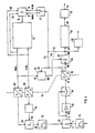
- Figure 1 shows this basic principle. This is a circuit for suppressing the fixed target echoes by means of a first order filter and for digitizing the moving target echoes.
- the sum signal of a receive converter array is fed to the positive input 4 of an analog subtractor 2.
- the output 6 is connected to the input 8 of an analog-digital converter or A / D converter 10.
- the A / D converter 10 digitizes the analog signal with 8 bits.
- the signal at the output 12 of the A / D converter 10 is fed both to a further signal processing circuit (not shown) and to an input 14 of a 16-bit digital adder 16. However, only the eight least significant or least significant bits (8 LSB ) occupied at input 14.
- the output of the adder 16 is connected to the input 18 of a 16-bit memory 20.
- the memory 20 is organized according to the "first in-first out (FIFO)" principle.
- the output 22 of the memory 20 is connected on the one hand to the input 24 of a 16-bit digital-to-analog converter or D / A converter 26 and others on the other hand via a feedback 27 to the second input 28 of the adder 16.
- the analog output 30 of the D / A converter 26 is connected to the inverting input 32 of the subtractor 2.
- the principle works as follows: The echo signals from an ultrasound scanning beam are stored digitally. The echoes on a subsequent transmission shot are deducted from the stored ones of the previous shot in the correct time. If there was no movement in the object, identical echo signals result in response to the transmission shots and the difference between the two signals is zero. Moving interfaces in the object lead to differences, the greater the faster the movement. The difference signal thus represents the linear frequency-weighted (differentiated) Doppler signal.
- the digitization is only carried out with the bit depth that the difference signal requires.
- the fixed target echo which requires a much wider range of words, is slowly gained by multiple addition of initially overdriven differential signals. The conversion back to analogue is possible because D / A converters are easier to implement than A / D converters.
- the process described is as follows:
- the analog difference signal from the subtractor 2 is converted by the A / D converter 10 with 8 bits and written into the memory 20 via the 16 bit adder 16. If the memory 20 is initially empty, only the value zero is added to the adder 16 via the feedback 27, so that the output signal of the A / D converter 10 is originally written. Since the subtractor 2 likewise initially only subtracts the value zero, the A / D converter 10 receives the full fixed target echo in the first step. Since this is much stronger than the moving target echoes, the A / D converter 10 is overdriven. Therefore, the maximum value of the 8-bit word is very often used as the LSB value in the Memory 20 registered.
- the output signal of this converter 10 represents the differentiated and pulsed Doppler signal in digital form.
- the dashed line 34 indicates the boundary between the analog and digital parts.
- each receive channel of an electronic array sector scanner i.e. such a system is associated with the undelayed signal of each elementary converter of the array.
- the same function groups are identified by the same reference symbols in FIG. 1 and FIG. 2.
- the output 6 of the subtractor 2 is connected on the one hand to the input 8 of the A / D converter 10 via a changeover switch 36.
- the output 6 is connected to the input 38 of an amplifier 40 via the changeover switch 36 to the input 8.
- the A / D converter converts the analog signal with a sampling rate of 30 MHz into a digital 8 bit signal.
- the output 12 of the A / D converter is now connected to the adder 16 via a changeover switch 42.
- the adder 16 here is a 14-bit adder.
- the switch 42 allows the 8-bit word to be fed via the input 15 to the 8 "most significant bits (8 MSB)" and on the other hand via the input 14 to the 6 "least significant bits (6 LSB)" of the adder 16.
- the memory 20 has a capacity of 4000 words with a length of 14 bits and is organized according to the "first in-first out (FIFO)" principle.
- the output 22 is connected via the feedback 27 to the input 28 of the adder 16.
- the output 30 of the D / A converter 26 is connected to the input 32 of the subtractor.
- the output 12 of the A / D converter 10 is connected to the input 44 of a signal memory 46.
- the digitized Doppler difference signal is stored in the memory 46 over a length of e.g. 1000 words with 8 bit length stored at 30 MHz sampling rate and delayed according to the requirements of pan and focus. At 30 MHz sampling rate, a maximum of 33 ⁇ s delay for the pan is achieved.
- the signal is also read out at 30 MHz and fed to the input 50 of a linear interpolator 52 via the output 48. The linear interpolation apparently doubles the sampling rate, so that center frequencies of 7 MHz can also be mastered.
- the digital signals of all channels delayed in accordance with the swivel angle and / or the focus position are added up and form the focused received high-frequency Doppler signal as a sum signal.
- a further digital comb filter (not shown), with or without interposed quadrature demodulation, which compensates for the frequency dependence of the transmission factor of the circuit for fixed target suppression.
- a frequency-independent, high-pass filtered Doppler signal is available for further processing.
- This type of broadband separation of the moving target echoes from the fixed target echoes is typically followed by the formation of the deep areas by means of signal gating (range gates).
- the amplifier 40 with the changeover switch 36 is now arranged between the subtractor 2 and the A / D converter 10.
- the signal is digitized so that the A / D converter 10 is not overloaded.
- the undistorted fixed target echoes are obtained in the signal memory 46 and, exactly as described above, one can electronically pan and focus by delay in order to build up a B-picture. Both the image signals (fixed target echoes) and the Doppler difference signals can therefore be stored in the signal memory 46.
- the image signals are in the signal memory 46 after the first transmission pulse or shot, while the Doppler difference signals are in the signal memory 46 after further shots in the same target area.
- this digital fixed target echo is now correctly applied to the 8 MSB inputs 15 of the adder 16 via the changeover switch 42.
- an echo signal stored with an accuracy of 8 bits is available for the difference formation in the subtractor 2. It does not have to be gained by addition. This saves time, which is particularly scarce anyway if a Doppler image (flow imaging) is to be produced. For reasons of time, no more than 10 shots per scanning direction can be permitted, although a much higher number would be desirable.
- the 8-bit A / D converter 10 compared to the ideal with a 14-bit A / D converter 10, only one shot per beam direction is lost compared to several in the operation of the circuit according to FIG. 1.
- Figure 3 shows an embodiment which manages with two D / A converters of smaller bit width than the D / A converter 26 in Figure 2. This makes the expensive, fast D / A converter 26 of large bit width, e.g. 14 bit, at 30 MHz sampling rate replaced by two inexpensive D / A converters 56 and 58. In addition, an error correction circuit is provided.
- the same functional units are given the same reference numerals as in FIGS. 1 and 2.
- the D / A converter 26 from FIG. 2 is divided into a D / A converter 56 for the 6 LSB and an 8 bit D / A converter 58 for the 8 MSB.
- the return 27 from FIG. 2 is divided into a 6-bit return 60 and an 8-bit return 62, which are connected to the adder 16 in the correct position.
- the signal at the output of the D / A converter 56 is fed to the input 66 of an analog summer 68 via an attenuator circuit 64.
- the attenuator circuit 64 reduces the amplitude of the signal by a factor of 1/64.
- the output of the second D / A converter 58 is fed to the other input 70 of the summer 68.
- the sum signal is fed to the inverting input 32 of the subtractor 2 via a low-pass filter 72.
- a similar low-pass filter 74 is connected upstream of the non-inverting input 4. The function of the low-pass filter is explained below.
- the error correction circuit described below is also intended to compensate for the non-linearities of the two D / A converters 58 and 59.
- a read-write memory 76 is connected with its address input 78 to the 8 MSB output of the memory 20.
- the write input 79 of the read-write memory 76 is connected to the output of the A / D converter 10 and the read output 80 to the inverting input 82 of a further subtractor 84.
- the subtractor 84 is connected with its input 86 to the digital output of the A / D converter 10 and with its output 88 to the memory input 44.
- the output 88 is also still connected to an overload indicator 90.
- converter 58 has a linearity that is accurate enough for 14 bits, and if the analog addition in summer 68 is error-free, the division of the 14 bits between the two D / A converters 56 and 58 is problem-free. In fact, one must assume that these ideal conditions do not exist.
- the read-write memory 76 and the subtractor 84 are provided. Correction values are stored in the read-write memory 76, which compensate for the errors of all components in the branch via which the previous signal is fed to the subtractor 2.
- This branch consists here of the converters 56 and 58, the attenuator 64, the summer 68 and the low-pass filter 72 and the subtractor 2. This is done in the manner described below.
- This voltage only rises so quickly that at the selected conversion rate of the A / D converter 10, all 256 binary values occur at least once.
- the memory 20 is deleted at the beginning.
- the 8 MSB are registered as explained in the description of FIG. 2 for the first shot.
- the same test signal is applied a second time and now with gain 64 through the amplifier 40 and the changeover switch 36 are fed to the A / D converter 10.
- the digital words thus obtained are added as LSB to the previously stored word series. Attention is paid to associated memory words for the same analog voltage.
- the memory 20 now contains the test signal shown with 14 bits.
- a new comparison with the test signal would give the deviation zero if no errors occurred.
- the errors actually present in the feedback branch given above, e.g. the linearity errors of converter 58 will result in a non-zero output signal from A / D converter 10.
- This deviation is now recorded in the memory 76.
- the deviation value at the output of the A / D converter 10 is read in for each output value of the memory 20, which is interpreted as the address for the memory 76.
- the deviation value stored in this way is subtracted from each converted word of the A / D converter 10 as a function of the 8 MSB of the memory 20 by the subtractor 84 before it is stored in the memory 46 as a Doppler signal. In this way, cheap D / A converters 56 and 58 can also be used.
- the correction is only dependent on the amplitude.
- the similar low-pass filters 72 and 74 are to be used before the A / D conversion or as an "anti-aliasing filter".
- FIG. 4 A circuit variant of FIG. 3 is shown in FIG. 4.
- the output 88 of the subtractor 84 is connected to the input of the changeover switch 42 via a first switch 92 with a make contact.
- a second switch 94 with an NC contact is inserted between the output of the A / D converter 10 and the input of the changeover switch 42.
- Switches 92 and 94 are switched simultaneously, which is shown by the dashed line 95, operated after the second shot. This means that the steady state memory 20 is written to the corrected value from the subtractor 84 instead of directly using the output signal of the A / D converter 10. It is thereby achieved that an exact 14 bit value lies in the memory 20.
- the subtractor 84 is located in the connecting line between the memory 20 and the A / D converter 56.
- the plus input 86 is with the 6 LSB output of the memory 20 and the output 88 is with the input of the D / A converter 56 connected. The same effect as when switching after the second shot in the circuit according to FIG. 4 is achieved without switching.
- the overload indicator 90 signals the case that the signal changes e.g. are too large due to motion artifacts to be converted undistorted. This information can e.g. used to mark or hide the Doppler signals as invalid.
- the entire control system for focusing and scanning the image system can be used unchanged for the Doppler signal processing circuit. This is not the case with an additional analog Doppler part.
- the proposed combination requires only a few adjustment procedures in the test field, the effort of which is less than that for a completely analog combination. It is also suitable for the installation of a self-diagnosis for test field, service and users.
Landscapes
- Engineering & Computer Science (AREA)
- Physics & Mathematics (AREA)
- Radar, Positioning & Navigation (AREA)
- Remote Sensing (AREA)
- Computer Networks & Wireless Communication (AREA)
- General Physics & Mathematics (AREA)
- Acoustics & Sound (AREA)
- Ultra Sonic Daignosis Equipment (AREA)
- Measurement Of Velocity Or Position Using Acoustic Or Ultrasonic Waves (AREA)
- Electrophonic Musical Instruments (AREA)
- Position Input By Displaying (AREA)
Applications Claiming Priority (2)
| Application Number | Priority Date | Filing Date | Title |
|---|---|---|---|
| DE8812400U | 1988-09-30 | ||
| DE8812400U DE8812400U1 (de) | 1988-09-30 | 1988-09-30 | Kombiniertes Ultraschall-Bild- und Dopplergerät |
Publications (2)
| Publication Number | Publication Date |
|---|---|
| EP0361264A1 true EP0361264A1 (fr) | 1990-04-04 |
| EP0361264B1 EP0361264B1 (fr) | 1994-08-10 |
Family
ID=6828473
Family Applications (1)
| Application Number | Title | Priority Date | Filing Date |
|---|---|---|---|
| EP89117241A Expired - Lifetime EP0361264B1 (fr) | 1988-09-30 | 1989-09-18 | Partie d'entreé numérique pour un appareil ultrasonique |
Country Status (5)
| Country | Link |
|---|---|
| US (1) | US4975885A (fr) |
| EP (1) | EP0361264B1 (fr) |
| JP (1) | JP2807285B2 (fr) |
| AT (1) | ATE109898T1 (fr) |
| DE (2) | DE8812400U1 (fr) |
Cited By (3)
| Publication number | Priority date | Publication date | Assignee | Title |
|---|---|---|---|---|
| EP0362820A3 (en) * | 1988-10-05 | 1990-10-31 | Kabushiki Kaisha Toshiba | Ultrasonic imaging apparatus |
| EP0430093A2 (fr) | 1989-11-27 | 1991-06-05 | Acoustic Imaging Technologies Corporation | Système d'imagerie doppler employant des ultrasons avec annuleur de signaux et contre-réaction analogique |
| EP0543595A1 (fr) * | 1991-11-20 | 1993-05-26 | Matsushita Electric Industrial Co., Ltd. | Formateur de faisceau pour appareil de diagnostic et ultrasons |
Families Citing this family (18)
| Publication number | Priority date | Publication date | Assignee | Title |
|---|---|---|---|---|
| US5555534A (en) * | 1994-08-05 | 1996-09-10 | Acuson Corporation | Method and apparatus for doppler receive beamformer system |
| US5685308A (en) * | 1994-08-05 | 1997-11-11 | Acuson Corporation | Method and apparatus for receive beamformer system |
| DE19581718T5 (de) * | 1994-08-05 | 2013-11-07 | Siemens Medical Solutions USA, Inc. (n.d. Ges. d. Staates Delaware) | Verfahren und Vorrichtung für Sendestrahlformersystem |
| US6029116A (en) * | 1994-08-05 | 2000-02-22 | Acuson Corporation | Method and apparatus for a baseband processor of a receive beamformer system |
| US5793701A (en) * | 1995-04-07 | 1998-08-11 | Acuson Corporation | Method and apparatus for coherent image formation |
| US5675554A (en) * | 1994-08-05 | 1997-10-07 | Acuson Corporation | Method and apparatus for transmit beamformer |
| US5549111A (en) * | 1994-08-05 | 1996-08-27 | Acuson Corporation | Method and apparatus for adjustable frequency scanning in ultrasound imaging |
| US5928152A (en) * | 1994-08-05 | 1999-07-27 | Acuson Corporation | Method and apparatus for a baseband processor of a receive beamformer system |
| US5581517A (en) * | 1994-08-05 | 1996-12-03 | Acuson Corporation | Method and apparatus for focus control of transmit and receive beamformer systems |
| US6050945A (en) * | 1997-06-27 | 2000-04-18 | Siemens Medical Systems, Inc. | Ultrasound front-end circuit combining the transmitter and automatic transmit/receive switch with agile power level control |
| US6074346A (en) * | 1997-06-27 | 2000-06-13 | Siemens Medical Systems, Inc. | Transmit/receive ultrasound front end circuit providing automatic transmit/receive switching |
| US6083164A (en) * | 1997-06-27 | 2000-07-04 | Siemens Medical Systems, Inc. | Ultrasound front-end circuit combining the transmitter and automatic transmit/receiver switch |
| US7377433B2 (en) * | 1998-07-22 | 2008-05-27 | Washington University In St. Louis | Method and apparatus for authenticating a magnetic fingerprint signal using compressive amplification |
| DE20200617U1 (de) * | 2002-01-15 | 2002-06-13 | DWL Elektronische Systeme GmbH, 78354 Sipplingen | Vorrichtung zur diagnostischen oder therapeutischen Ultraschallsonographie |
| US7791282B2 (en) * | 2006-11-28 | 2010-09-07 | Hubbell Incorporated | Motion sensor switch for 3-way light circuit and method of lighting control using the same |
| CA2873391A1 (fr) * | 2012-05-11 | 2013-11-14 | Volcano Corporation | Dispositif et systeme d'imagerie et de mesure de la vitesse d'ecoulement du sang |
| GB2515073B (en) * | 2013-06-13 | 2017-12-13 | Gen Electric | Imaging or analysis of flowing media |
| JP2015021829A (ja) * | 2013-07-18 | 2015-02-02 | パナソニック株式会社 | 移動体検出装置 |
Citations (6)
| Publication number | Priority date | Publication date | Assignee | Title |
|---|---|---|---|---|
| FR2375764A1 (fr) * | 1976-12-22 | 1978-07-21 | Hoffmann La Roche | Circuit de filtre |
| WO1981000807A1 (fr) * | 1979-09-20 | 1981-04-02 | Commw Of Australia | Equipement de traitement de signaux pour visualisation ultrasonique |
| US4324258A (en) * | 1980-06-24 | 1982-04-13 | Werner Huebscher | Ultrasonic doppler flowmeters |
| GB2088668A (en) * | 1980-11-24 | 1982-06-09 | Marconi Co Ltd | A technique for reducing the effect of reflections from the sea or other surface on radar and other electromagnetic receiving/transmitting apparatus |
| EP0081045A1 (fr) * | 1981-12-03 | 1983-06-15 | Kabushiki Kaisha Toshiba | Installation de diagnostic par ultrasons |
| DE3445169A1 (de) * | 1984-12-11 | 1986-06-19 | Siemens AG, 1000 Berlin und 8000 München | Ultraschallgeraet mit schaltbarem pegel |
Family Cites Families (5)
| Publication number | Priority date | Publication date | Assignee | Title |
|---|---|---|---|---|
| US4318413A (en) * | 1978-10-20 | 1982-03-09 | Tokyo Shibaura Denki Kabushiki Kaisha | Ultrasonic diagnostic apparatus |
| DE2942049A1 (de) * | 1979-10-17 | 1981-05-21 | Siemens AG, 1000 Berlin und 8000 München | Vorrichtung zur ultraschallabtastung |
| US4408495A (en) * | 1981-10-02 | 1983-10-11 | Westinghouse Electric Corp. | Fiber optic system for measuring mechanical motion or vibration of a body |
| DE3425705A1 (de) * | 1984-07-12 | 1986-01-16 | Siemens AG, 1000 Berlin und 8000 München | Phased-array-geraet |
| JPS63317141A (ja) * | 1987-06-22 | 1988-12-26 | Toshiba Corp | 超音波診断装置 |
-
1988
- 1988-09-30 DE DE8812400U patent/DE8812400U1/de not_active Expired
-
1989
- 1989-09-18 DE DE58908175T patent/DE58908175D1/de not_active Expired - Lifetime
- 1989-09-18 AT AT89117241T patent/ATE109898T1/de active
- 1989-09-18 EP EP89117241A patent/EP0361264B1/fr not_active Expired - Lifetime
- 1989-09-27 US US07/413,293 patent/US4975885A/en not_active Expired - Lifetime
- 1989-09-29 JP JP1255113A patent/JP2807285B2/ja not_active Expired - Lifetime
Patent Citations (6)
| Publication number | Priority date | Publication date | Assignee | Title |
|---|---|---|---|---|
| FR2375764A1 (fr) * | 1976-12-22 | 1978-07-21 | Hoffmann La Roche | Circuit de filtre |
| WO1981000807A1 (fr) * | 1979-09-20 | 1981-04-02 | Commw Of Australia | Equipement de traitement de signaux pour visualisation ultrasonique |
| US4324258A (en) * | 1980-06-24 | 1982-04-13 | Werner Huebscher | Ultrasonic doppler flowmeters |
| GB2088668A (en) * | 1980-11-24 | 1982-06-09 | Marconi Co Ltd | A technique for reducing the effect of reflections from the sea or other surface on radar and other electromagnetic receiving/transmitting apparatus |
| EP0081045A1 (fr) * | 1981-12-03 | 1983-06-15 | Kabushiki Kaisha Toshiba | Installation de diagnostic par ultrasons |
| DE3445169A1 (de) * | 1984-12-11 | 1986-06-19 | Siemens AG, 1000 Berlin und 8000 München | Ultraschallgeraet mit schaltbarem pegel |
Cited By (5)
| Publication number | Priority date | Publication date | Assignee | Title |
|---|---|---|---|---|
| EP0362820A3 (en) * | 1988-10-05 | 1990-10-31 | Kabushiki Kaisha Toshiba | Ultrasonic imaging apparatus |
| US5050611A (en) * | 1988-10-05 | 1991-09-24 | Kabushiki Kaisha Toshiba | Ultrasonic imaging apparatus |
| EP0430093A2 (fr) | 1989-11-27 | 1991-06-05 | Acoustic Imaging Technologies Corporation | Système d'imagerie doppler employant des ultrasons avec annuleur de signaux et contre-réaction analogique |
| EP0543595A1 (fr) * | 1991-11-20 | 1993-05-26 | Matsushita Electric Industrial Co., Ltd. | Formateur de faisceau pour appareil de diagnostic et ultrasons |
| US5263483A (en) * | 1991-11-20 | 1993-11-23 | Matsushita Electric Industrial Co., Ltd. | Beam former for ultrasonic diagnostic apparatus |
Also Published As
| Publication number | Publication date |
|---|---|
| JP2807285B2 (ja) | 1998-10-08 |
| US4975885A (en) | 1990-12-04 |
| DE8812400U1 (de) | 1989-04-06 |
| DE58908175D1 (de) | 1994-09-15 |
| ATE109898T1 (de) | 1994-08-15 |
| EP0361264B1 (fr) | 1994-08-10 |
| JPH02143185A (ja) | 1990-06-01 |
Similar Documents
| Publication | Publication Date | Title |
|---|---|---|
| EP0361264B1 (fr) | Partie d'entreé numérique pour un appareil ultrasonique | |
| DE68917437T2 (de) | In unterbereiche geteilter analog-digitalwandler mit eichung. | |
| DE3640672C2 (fr) | ||
| EP0219098B1 (fr) | Dispositif de traitement des signaux d'image pour un système de représentation image ultrasonore et dispositif de représentation | |
| DE69015373T2 (de) | Digital-analog-wandler mit grossem dynamikbereich, hoher genauigkeit und hoher geschwindigkeit. | |
| EP0170072A1 (fr) | Dispositif de groupement phasé | |
| DE2066199C3 (de) | Radaranlage mit Festzielunterdrückung | |
| DE19502399A1 (de) | Positionsmeldevorrichtung mit Erfassung einer absoluten Position und zugehöriges Verfahren zur Fehlerkorrektur | |
| DE2141589C3 (de) | Radarsystem mit Festzeichenunterdrückung unter rauschechogesteuerter Phasenkorrektur der kohärenten Bezugsschwingung | |
| DE3935617A1 (de) | Infrarot-fouriertransformations-spektrometer | |
| DE3603042A1 (de) | Ultraschallgeraet mit dynamischer veraenderung der empfangsfokuslage | |
| EP1207372B1 (fr) | Procédé et appareil pour le conditionnement d'un signal analogique périodique | |
| EP0324897A1 (fr) | Système de radar à dispositif expanseur numérique | |
| EP0119529B1 (fr) | Procédé de conversion analogique-numérique | |
| EP0736977A1 (fr) | Procédé d'autocalibrage d'un convertisseur analogique-numérique ou d'un convertisseur numérique-analogique | |
| DE3337041C1 (de) | Schaltungsvorrichtung zur Logarithmierung und Digitalisierung analoger Signale | |
| EP0406878B1 (fr) | Dispositif d'atténuation d'échos proches | |
| WO1990014717A1 (fr) | Convertisseur numerique-analogique a haute linearite | |
| DE68912866T2 (de) | Ultraschall-Abbildungsgerät. | |
| DE2912925C2 (de) | Verfahren und Anordnung zur schnellen hochauflösenden Analog/Digital-Umsetzung mit selbständiger Korrektur | |
| EP0177803B1 (fr) | Méthode et dispositif de numérisation d'un signal à haute résolution | |
| EP0381038A1 (fr) | Système radar | |
| EP0378777A2 (fr) | Agencement de conversion de signaux analogiques en signaux numériques | |
| EP0404237B1 (fr) | Méthode et dispositif de suppression de bruit d'un signal numérique | |
| DE3889556T2 (de) | Hochauflösendes automatisches elektronisches Brennpunktkorrekturuntersystem für Elektronenstrahllithographie. |
Legal Events
| Date | Code | Title | Description |
|---|---|---|---|
| PUAI | Public reference made under article 153(3) epc to a published international application that has entered the european phase |
Free format text: ORIGINAL CODE: 0009012 |
|
| AK | Designated contracting states |
Kind code of ref document: A1 Designated state(s): AT CH DE FR GB LI NL |
|
| 17P | Request for examination filed |
Effective date: 19900427 |
|
| 17Q | First examination report despatched |
Effective date: 19920721 |
|
| GRAA | (expected) grant |
Free format text: ORIGINAL CODE: 0009210 |
|
| AK | Designated contracting states |
Kind code of ref document: B1 Designated state(s): AT CH DE FR GB LI NL |
|
| PG25 | Lapsed in a contracting state [announced via postgrant information from national office to epo] |
Ref country code: FR Effective date: 19940810 Ref country code: NL Effective date: 19940810 |
|
| REF | Corresponds to: |
Ref document number: 109898 Country of ref document: AT Date of ref document: 19940815 Kind code of ref document: T |
|
| REF | Corresponds to: |
Ref document number: 58908175 Country of ref document: DE Date of ref document: 19940915 |
|
| GBT | Gb: translation of ep patent filed (gb section 77(6)(a)/1977) |
Effective date: 19940927 |
|
| EN | Fr: translation not filed | ||
| NLV1 | Nl: lapsed or annulled due to failure to fulfill the requirements of art. 29p and 29m of the patents act | ||
| PLBE | No opposition filed within time limit |
Free format text: ORIGINAL CODE: 0009261 |
|
| STAA | Information on the status of an ep patent application or granted ep patent |
Free format text: STATUS: NO OPPOSITION FILED WITHIN TIME LIMIT |
|
| 26N | No opposition filed | ||
| PGFP | Annual fee paid to national office [announced via postgrant information from national office to epo] |
Ref country code: GB Payment date: 19950821 Year of fee payment: 7 |
|
| PGFP | Annual fee paid to national office [announced via postgrant information from national office to epo] |
Ref country code: AT Payment date: 19950825 Year of fee payment: 7 |
|
| PGFP | Annual fee paid to national office [announced via postgrant information from national office to epo] |
Ref country code: CH Payment date: 19951215 Year of fee payment: 7 |
|
| PG25 | Lapsed in a contracting state [announced via postgrant information from national office to epo] |
Ref country code: AT Effective date: 19960918 Ref country code: GB Effective date: 19960918 |
|
| PG25 | Lapsed in a contracting state [announced via postgrant information from national office to epo] |
Ref country code: LI Effective date: 19960930 Ref country code: CH Effective date: 19960930 |
|
| GBPC | Gb: european patent ceased through non-payment of renewal fee |
Effective date: 19960918 |
|
| REG | Reference to a national code |
Ref country code: CH Ref legal event code: PL |
|
| PGFP | Annual fee paid to national office [announced via postgrant information from national office to epo] |
Ref country code: DE Payment date: 20081121 Year of fee payment: 20 |