EP0361329A1 - Pompe à jet auto-amorçante avec éjecteur incorporé - Google Patents
Pompe à jet auto-amorçante avec éjecteur incorporé Download PDFInfo
- Publication number
- EP0361329A1 EP0361329A1 EP89117554A EP89117554A EP0361329A1 EP 0361329 A1 EP0361329 A1 EP 0361329A1 EP 89117554 A EP89117554 A EP 89117554A EP 89117554 A EP89117554 A EP 89117554A EP 0361329 A1 EP0361329 A1 EP 0361329A1
- Authority
- EP
- European Patent Office
- Prior art keywords
- ejector
- pump casing
- diaphragm
- pump
- suction
- Prior art date
- Legal status (The legal status is an assumption and is not a legal conclusion. Google has not performed a legal analysis and makes no representation as to the accuracy of the status listed.)
- Granted
Links
- 206010008469 Chest discomfort Diseases 0.000 claims abstract description 18
- 238000000465 moulding Methods 0.000 claims description 6
- 238000007493 shaping process Methods 0.000 claims 4
- 238000004519 manufacturing process Methods 0.000 description 7
- 238000005266 casting Methods 0.000 description 6
- 238000004512 die casting Methods 0.000 description 3
- 239000002184 metal Substances 0.000 description 3
- 239000007787 solid Substances 0.000 description 3
- XLYOFNOQVPJJNP-UHFFFAOYSA-N water Substances O XLYOFNOQVPJJNP-UHFFFAOYSA-N 0.000 description 3
- 238000012423 maintenance Methods 0.000 description 2
- 239000000463 material Substances 0.000 description 2
- 238000000034 method Methods 0.000 description 2
- 238000012986 modification Methods 0.000 description 2
- 230000004048 modification Effects 0.000 description 2
- 238000003466 welding Methods 0.000 description 2
- 238000004026 adhesive bonding Methods 0.000 description 1
- 230000015572 biosynthetic process Effects 0.000 description 1
- 238000004140 cleaning Methods 0.000 description 1
- 238000007689 inspection Methods 0.000 description 1
- 238000005304 joining Methods 0.000 description 1
- 239000007788 liquid Substances 0.000 description 1
- 238000010137 moulding (plastic) Methods 0.000 description 1
- 238000005192 partition Methods 0.000 description 1
- 230000000063 preceeding effect Effects 0.000 description 1
- 230000037452 priming Effects 0.000 description 1
- 238000007789 sealing Methods 0.000 description 1
- 238000000926 separation method Methods 0.000 description 1
- 238000010112 shell-mould casting Methods 0.000 description 1
Images

Classifications
-
- F—MECHANICAL ENGINEERING; LIGHTING; HEATING; WEAPONS; BLASTING
- F04—POSITIVE - DISPLACEMENT MACHINES FOR LIQUIDS; PUMPS FOR LIQUIDS OR ELASTIC FLUIDS
- F04D—NON-POSITIVE-DISPLACEMENT PUMPS
- F04D9/00—Priming; Preventing vapour lock
- F04D9/04—Priming; Preventing vapour lock using priming pumps; using booster pumps to prevent vapour-lock
- F04D9/06—Priming; Preventing vapour lock using priming pumps; using booster pumps to prevent vapour-lock of jet type
-
- F—MECHANICAL ENGINEERING; LIGHTING; HEATING; WEAPONS; BLASTING
- F04—POSITIVE - DISPLACEMENT MACHINES FOR LIQUIDS; PUMPS FOR LIQUIDS OR ELASTIC FLUIDS
- F04D—NON-POSITIVE-DISPLACEMENT PUMPS
- F04D29/00—Details, component parts, or accessories
- F04D29/40—Casings; Connections of working fluid
- F04D29/42—Casings; Connections of working fluid for radial or helico-centrifugal pumps
- F04D29/426—Casings; Connections of working fluid for radial or helico-centrifugal pumps especially adapted for liquid pumps
Definitions
- the invention concerns a self-priming jet pump with a pump casing without any undercut, the seats of the ejector for its connection with the pump casing being coaxial with the rotation axis of the impeller and the suction connection being positioned at the front end of the pump above the rotation axis.
- Centrifugal, self-priming jet pumps usually known as "Jet” pumps are special types of centrifugal pumps combined with a venturi ejector, which are used in several domains and for a plurality of applications, such as drawing water out of a well or, more in general, drawing liquids from tanks placed at a certain depth. They may also be used as pressure boosting pumps for central low pressure water systems.
- the self-priming jet pumps are built with a pump casing containing the suction chamber and the pressure chamber, which are obtained by dividing the inner volume of the pump casing by means of partitions.
- Said forms of execution entail some difficulty in the manufacture of the pump casing, because of the presence of the undercuts, which require, when the pump casing is a single piece obtained through casting, the use of complicated dies and the necessity of inserting cores. Even when the pump casing is obtained through die drawing, it requires some complex carpentry operations for the welding of the added diaphragms.
- the pump casing is built without undercuts, since it contains the suction chamber in the ejector unit, which is directly connected with the suction connection positioned above the rotation axis.
- This type of execution entails the inconvenience that the ejector presents closed chambers, obtained through casting with a core, as disclosed in the US patent 2 700 338, or through die-drawing and then joining together several parts by welding or by means of screws or of snap hooks or by other means and by interposing sealing or gluing materials, which make the disassembly and the ensuing re-assembly difficult and sometimes impossible.
- Said types of execution also entail the inconvenience that the presence of the closed chambers make it difficult to check whether within the pump casing or the ejector there are foreign bodies which may have entered accidentally while the pump was operating or whether there are settling solids.
- the pump casing is made without any undercut and the seats for the connection of the ejector are coaxial with the axis of rotation while the suction connection is positioned on the plane passing through the axis of rotation, as disclosed for instance in the US patent 2 934 021.
- Such an execution presents the inconvenience of preventing the pump casing from filling up with a sufficient amount of water at the initial priming, unless there is a check valve in the suction pipe.
- the purpose of the present invention is that of overcoming the mentioned inconveniences.
- the main purpose of the invention is to obtain a centrifugal self-priming jet pump, whose pump casing does not present any undercuts and can be obtained by die-casting without core or by shell moulding or die-drawing and whose ejector consists of a single body made without closed chambers which is, therefore, easy to make by die-drawing and to check.
- Another purpose of the invention is that of obtaining a centrifugal self-priming pump, whose pump casing presents the seats for the connection of the ejector being coaxial with the rotation axis of the impeller, so as to make it easily machinable, if necessary, by using a lathe.
- Another purpose of the invention is that of obtaining a self-priming jet pump, wherein the nozzle is positioned eccentrically in the ejector collar, in order to obtain an anti-vortex arrangement in the supplying high-pressure chest.
- the last but not the least purpose is that of obtaining a centrifugal self-priming jet pump which is easy to assemble and to disassemble.
- a self-priming jet pump comprising a pump casing complete with a suction connection and a delivery connection, within which a unit consisting of an ejector and a nozzle is arranged, said jet pump being characterized in that the pump casing presents a shape lacking undercut surfaces, since it is obtained by a moulding process using two axially counterposed plungers, one of which shapes the inner volume of the pump, while the other shapes the suction connection, said pump casing being provided with seats for the connection of the ejector which are coaxial with the rotation axis of the impeller.
- said ejector presents a transversally arranged diaphragm, which is suited to divide the inner volume of the pump casing, so as to realize a suction chamber and a pressure chamber, and a frontal collar which is suited to divide the suction chamber, so as to realize a duct and a high-pressure chest for supplying the nozzle.
- Said nozzle is connected in the ejector collar in an eccentric position. Moreover, the suction connection is positioned frontally above the collar and it is partially or completely circumscribed by the diaphragm.
- a more economical centrifugal self-priming pump is obtained, since the pump casing is easier to manufacture because of the absence of the undercuts and easier to machine in case it is obtained through casting because of the co-axiality of the seats for the connection of the ejector with the rotation axis of the impeller. Moreover, the absence of the undercuts in the pump casing permits to check completely and immediately whether any foreign bodies or settling solids are present in its interior, while the ejector drawn in a single body without any closed chambers also presents the advantage that it can be totally and immediately checked.
- the eccentric arrangement of the nozzle in the ejector collar yields the advantage, in comparison with a coaxial arrangement, of a larger cross-section of the driving medium channel through the collar, of a larger cross-section for the passage of the suction around the nozzle and of a minimum volume of the air pocket in the high-pressure chest at the first filling.
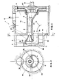
- the pump according to the invention which is indicated as a whole with 1 in Fig. 1, consists of a pump casing 2 presenting in its interior the suction chamber 3, which is connected with the suction connection 4, and the pressure-chamber 5, which is connected with the delivery connection 6.
- the suction chamber 3 and the pressure chamber 5 are obtained through the separation of the inner volume of the pump casing 2 by means of a diaphragm 7, constituting a single body with ejector 8 and being arranged radially with an external diameter which is coaxial with axis 21 of impeller 22.
- suction chamber 3 presents in its interior a collar 10 arranged on the front part of ejector 8 and also constituting a single body with the ejector, said collar having also an external diameter which is coaxial with axis 21 and defining a high-pressure chest 11 for supplying nozzle 12 with the driving medium, which enters the supplying high-pressure chest 11 through channel 24 in the direction indicated by arrow 13.
- the pump casing 2 is made so as not to present any undercut in the front in the moulding directions indicated by the arrows 14 in Fig. 3, which makes it possible to obtain the pump casing 2 through casting by using a die with two plungers and without a core.
- the pump casing 2 can also be obtained through die-drawing of a metal sheet or by plastic moulding, since, as can be observed in Fig. 3, opening 15 for the lodging of diaphragm 7, can be obtained by means of a plunger 16, while the opening of the suction connection 4 can be obtained by means of a plunger 17 counterposed to the preceeding one.
- the first purpose of the invention has been fulfilled. It concerned the realization of a centrifugal self-priming jet pump whose pump casing can be obtained through die-casting or die-drawing by using simple dies, thanks to the lack of undercuts.
- the ejector-nozzle unit 19 is assembled within the pump casing by connecting diaphragm 7 of ejector 8 with seat 15 and collar 10 of the ejector 8 itself on seat 20 obtained on the vertical wall 80 of the pump casing 2 arranged facing impeller 22.
- the high-pressure chest presents an axial symmetry within the round-shaped seat 20 for the connection of collar 10 of ejector 8.
- the drawings show a preferred assembly position of the nozzle-ejector unit 19 with nozzle 12 at the top and channel 24 at the bottom, the nozzle-ejector unit 19 can also be assembled within the seats 15 and 20 at different angular positions, without thereby compromising the operation of the pump. It is this form of execution which permits an easy assembly and disassembly of the nozzle-ejector unit 19 on and from the pump casing 2, which makes it easier to perform maintenance and check-up operations on the pump.
- the seats 15 and 20 present a transversal round-shaped cross-section and that they are coaxial with each other and with the axis 21 of rotation of impeller 22 and that they are, therefore, easily machinable, for instance, with a lathe, after the casting or die-drawing of the pump casing 2, in the case that the latter requires a finishing working process.
- collar 10 connected with ejector 8 which creates the high-pressure chest 11 contains channel 24 supplying the driving medium flowing from impeller 22 and entering channel 24 in the direction 13.
- Nozzle 12 is coaxial with axis 9 of the venturi tube of ejector 8 and it is eccentrically arranged with eccentricity 23 in relation to the axis 21 of rotation of impellar 22 and of the seats 15 and 20 in the pump casing 2.
- the area of section 81 for the passage of the induced medium around nozzle 12 is also made as large as possible, since as can observed in Fig. 2, the passage area 81 also includes area 25 arranged below axis 9 of nozzle 12 in ejector 8, area 25 representing the area increase ensuing from the off-center arrangement 23 between the axes 9 and 21 of the nozzle-ejector unit 19.
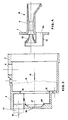
- Fig. 5 shows a first embodiment, wherein the entire inner part of the pump casing 30 can be moulded with a single plunger, while diaphragm 32 belonging to ejector 33 circumscribes completely the suction connection 34, comprised between the seats 31 and 36 for the connection of ejector 33 within the pump casing 30.
- FIG. 6 represents another embodiment, wherein the pump casing 40 presents the same characteristics of the previously described pump casing 30, while diaphragm 42, which in this case, too, circumscribes and contains completely the suction connection 44, is separated from the ejector 43 and consists of a round-shaped crown inserted within seat 41 of the pump casing 40, while ejector 43 is inserted within seat 46 in the pump casing 40 and within seat 49 in diaphragm 42.
- Fig. 7 shows another embodiment, wherein the inner part of the pump casing 50 presents the same moulding characteristics of its inner part with a single plunger, as in the already described examples of the pump casings 30 and 40.
- diaphragm 52 is separated from ejector 53 and, since it is shaped as a dome inserted within seat 51 of the pump casing 50, it includes also the high-pressure chest 55 and the seats 56 and 59 for the connection of ejector 53.
- One or more openings 58 obtained on dome 52 between the seats 56 and 59 constitute the suction passages.
- the pump casing 60 is preferably made of a die-drawn metal sheet with a suction connection 64 welded on its exterior, where the suction passage 68 is to be found, which is obtained between the seats 66 and 69.
- diaphragm 62 as the previously described diaphragm 52 of Fig. 7, besides incorporating the high-pressure chest 65 and the seats 66 and 69 for the connection of collar 67 of ejector 63, also constitutes a single body together with the pump casing 60.
- Fig. 9 shows yet another embodiment, wherein the pump casing 70 is preferably made of a die-drawn metal sheet and it presents the same moulding characteristics of its inner part with a single plunger, as has been described for the previously described pump casings 30, 40 and 50 and it also includes the suction connection 74 and the high-pressure chest 75, while diaphragm 72, which in this case, too, circumscribes and contains completely the suction connection 74, is separated from ejector 73 and is inserted within seat 71 of the pump casing 70.
- the pump casing 70 is preferably made of a die-drawn metal sheet and it presents the same moulding characteristics of its inner part with a single plunger, as has been described for the previously described pump casings 30, 40 and 50 and it also includes the suction connection 74 and the high-pressure chest 75, while diaphragm 72, which in this case, too, circumscribes and contains completely the suction connection 74, is separated from ejector 73 and is inserted within seat 71 of the
- Ejector 73 is inserted within seat 76 in the pump casing 70 and within seat 79 of diaphragm 72.
- the outer diameter of diaphragm 72 and its seat 71 within the pump casing 70 can be made concentrical with the inner diameter and coaxial with seat 76, as the previously described diaphragm 42.
- the pump casing can be made with the seats for the connection of the diaphragm and of the ejector collar, which are co-axial with the axis of rotation of the impeller, in order to be machined more easily.
- the special off-center arrangement of the axis of the nozzle in relation to the axis of rotation of the impeller permits to eliminate vortexes in the high-pressure chest for supplying the nozzle with the driving medium and it also makes it possible to enlarge as much as possible the section area for the passage of the driving medium through the collar and through the suction opening around the nozzle.
Landscapes
- Engineering & Computer Science (AREA)
- Mechanical Engineering (AREA)
- General Engineering & Computer Science (AREA)
- Structures Of Non-Positive Displacement Pumps (AREA)
- Jet Pumps And Other Pumps (AREA)
Applications Claiming Priority (2)
| Application Number | Priority Date | Filing Date | Title |
|---|---|---|---|
| IT8564388 | 1988-09-26 | ||
| IT8885643A IT1225596B (it) | 1988-09-26 | 1988-09-26 | Pompa autoadescante ad eiettore. |
Publications (2)
| Publication Number | Publication Date |
|---|---|
| EP0361329A1 true EP0361329A1 (fr) | 1990-04-04 |
| EP0361329B1 EP0361329B1 (fr) | 1992-01-29 |
Family
ID=11329474
Family Applications (1)
| Application Number | Title | Priority Date | Filing Date |
|---|---|---|---|
| EP89117554A Expired EP0361329B1 (fr) | 1988-09-26 | 1989-09-22 | Pompe à jet auto-amorçante avec éjecteur incorporé |
Country Status (4)
| Country | Link |
|---|---|
| EP (1) | EP0361329B1 (fr) |
| DE (1) | DE68900795D1 (fr) |
| ES (1) | ES2029549T3 (fr) |
| IT (1) | IT1225596B (fr) |
Cited By (12)
| Publication number | Priority date | Publication date | Assignee | Title |
|---|---|---|---|---|
| EP0864760A3 (fr) * | 1997-03-15 | 1999-08-18 | Grundfos A/S | Carter de pompe moulable pour ensemble motopompe, pour montage sur la paroi d'un dispositif |
| EP1111244A2 (fr) | 1999-12-23 | 2001-06-27 | Grundfos A/S | Pompe auto-amorçante |
| RU2175406C1 (ru) * | 2000-05-26 | 2001-10-27 | Несытов Евгений Константинович | Центробежный самовсасывающий насос |
| ES2161191A1 (es) * | 2000-03-27 | 2001-11-16 | Bogemar Sl | Bomba centrifuga con hidroeyector. |
| CN101581312B (zh) * | 2009-06-10 | 2011-06-29 | 江苏大学 | 一种大流量自吸泵 |
| CN102562604A (zh) * | 2011-12-22 | 2012-07-11 | 安徽江南泵阀有限公司 | 高性能耐强腐蚀自吸泵 |
| WO2020013729A1 (fr) | 2018-07-10 | 2020-01-16 | Yazykov Andrey Yurievich | Pompe centrifuge |
| CN111268438A (zh) * | 2020-02-28 | 2020-06-12 | 江苏大学 | 一种过流无损多相混输泵 |
| CN112555137A (zh) * | 2020-12-14 | 2021-03-26 | 宁波君禾智能科技有限公司 | 水泵控制系统 |
| CN112703320A (zh) * | 2018-09-12 | 2021-04-23 | 倍得龙有限公司 | 自吸式离心泵 |
| CN115059621A (zh) * | 2022-07-09 | 2022-09-16 | 兰州工业学院 | 一种脉冲射流自吸泵 |
| CN115199594A (zh) * | 2022-07-14 | 2022-10-18 | 兰州理工大学 | 一种射流自吸泵 |
Citations (4)
| Publication number | Priority date | Publication date | Assignee | Title |
|---|---|---|---|---|
| FR1022632A (fr) * | 1950-07-28 | 1953-03-06 | Perfectionnement aux pompes centrifuges | |
| US2700338A (en) * | 1950-11-15 | 1955-01-25 | Barnes Mfg Co | Shallow well centrifugal pump with jet |
| US2934021A (en) * | 1956-10-09 | 1960-04-26 | F E Meyers & Bro Co | Shallow well self-priming jet pump |
| US3394655A (en) * | 1966-09-19 | 1968-07-30 | Richard J. Brown | Combined centrifugal and jet type fluid pump |
-
1988
- 1988-09-26 IT IT8885643A patent/IT1225596B/it active
-
1989
- 1989-09-22 EP EP89117554A patent/EP0361329B1/fr not_active Expired
- 1989-09-22 DE DE8989117554T patent/DE68900795D1/de not_active Expired - Lifetime
- 1989-09-22 ES ES198989117554T patent/ES2029549T3/es not_active Expired - Lifetime
Patent Citations (4)
| Publication number | Priority date | Publication date | Assignee | Title |
|---|---|---|---|---|
| FR1022632A (fr) * | 1950-07-28 | 1953-03-06 | Perfectionnement aux pompes centrifuges | |
| US2700338A (en) * | 1950-11-15 | 1955-01-25 | Barnes Mfg Co | Shallow well centrifugal pump with jet |
| US2934021A (en) * | 1956-10-09 | 1960-04-26 | F E Meyers & Bro Co | Shallow well self-priming jet pump |
| US3394655A (en) * | 1966-09-19 | 1968-07-30 | Richard J. Brown | Combined centrifugal and jet type fluid pump |
Cited By (16)
| Publication number | Priority date | Publication date | Assignee | Title |
|---|---|---|---|---|
| EP0864760A3 (fr) * | 1997-03-15 | 1999-08-18 | Grundfos A/S | Carter de pompe moulable pour ensemble motopompe, pour montage sur la paroi d'un dispositif |
| EP1111244A2 (fr) | 1999-12-23 | 2001-06-27 | Grundfos A/S | Pompe auto-amorçante |
| EP1111244A3 (fr) * | 1999-12-23 | 2002-05-15 | Grundfos A/S | Pompe auto-amorçante |
| ES2161191A1 (es) * | 2000-03-27 | 2001-11-16 | Bogemar Sl | Bomba centrifuga con hidroeyector. |
| RU2175406C1 (ru) * | 2000-05-26 | 2001-10-27 | Несытов Евгений Константинович | Центробежный самовсасывающий насос |
| CN101581312B (zh) * | 2009-06-10 | 2011-06-29 | 江苏大学 | 一种大流量自吸泵 |
| CN102562604A (zh) * | 2011-12-22 | 2012-07-11 | 安徽江南泵阀有限公司 | 高性能耐强腐蚀自吸泵 |
| WO2020013729A1 (fr) | 2018-07-10 | 2020-01-16 | Yazykov Andrey Yurievich | Pompe centrifuge |
| CN112703320A (zh) * | 2018-09-12 | 2021-04-23 | 倍得龙有限公司 | 自吸式离心泵 |
| CN112703320B (zh) * | 2018-09-12 | 2023-02-28 | 倍得龙有限公司 | 自吸式离心泵 |
| CN111268438A (zh) * | 2020-02-28 | 2020-06-12 | 江苏大学 | 一种过流无损多相混输泵 |
| CN111268438B (zh) * | 2020-02-28 | 2022-02-22 | 江苏大学 | 一种过流无损多相混输泵 |
| CN112555137A (zh) * | 2020-12-14 | 2021-03-26 | 宁波君禾智能科技有限公司 | 水泵控制系统 |
| CN115059621A (zh) * | 2022-07-09 | 2022-09-16 | 兰州工业学院 | 一种脉冲射流自吸泵 |
| CN115059621B (zh) * | 2022-07-09 | 2023-10-27 | 兰州工业学院 | 一种脉冲射流自吸泵 |
| CN115199594A (zh) * | 2022-07-14 | 2022-10-18 | 兰州理工大学 | 一种射流自吸泵 |
Also Published As
| Publication number | Publication date |
|---|---|
| DE68900795D1 (de) | 1992-03-12 |
| ES2029549T3 (es) | 1992-08-16 |
| IT8885643A0 (it) | 1988-09-26 |
| EP0361329B1 (fr) | 1992-01-29 |
| IT1225596B (it) | 1990-11-22 |
Similar Documents
| Publication | Publication Date | Title |
|---|---|---|
| EP0361329B1 (fr) | Pompe à jet auto-amorçante avec éjecteur incorporé | |
| US4820131A (en) | Venturi nozzle assembly construction in a shallow well pump casing | |
| US3188966A (en) | Rotodynamic volute machines | |
| KR970010514B1 (ko) | 판금제 원심펌프 케이싱 | |
| CA2046983C (fr) | Pompe centrifuge | |
| US5184937A (en) | Centrifugal pump casing | |
| EP0552661B1 (fr) | Pompe centrifuge auto-amorçante | |
| EP1743101B1 (fr) | Pompe centrifuge et son procede de fabrication | |
| US2677327A (en) | Centrifugal pump construction | |
| US2765748A (en) | Centrifugal blowers or pumps | |
| US6267555B1 (en) | Sheet metal casing for multistage pump and method for manufacturing the same | |
| JPH09144698A (ja) | 中間吸込付き多段遠心圧縮機 | |
| US2960937A (en) | Submersible pump | |
| CN212429226U (zh) | 一种焊接结构的多级离心风机 | |
| JP2987024B2 (ja) | 板金製ポンプケーシング | |
| US5235744A (en) | Method of manufacturing a centrifugal pump casing | |
| KR100310922B1 (ko) | 스크롤형압축기 | |
| US2810346A (en) | Shallow well pump | |
| EP1020644B1 (fr) | Machine a fluide, bride pour ce type de machine, et procede de fabrication | |
| JP2528807Y2 (ja) | ポンプの鋼板製中間ケーシング | |
| US5551839A (en) | Pump housing for rotary pumps | |
| EP0093483A2 (fr) | Pompe centrifuge | |
| JPH0424158Y2 (fr) | ||
| ITMI971085A1 (it) | Flangia di raccordo | |
| EP1650440A1 (fr) | Carter de pompe ameliore pour pompe centrifuge et procede de production de ce carter |
Legal Events
| Date | Code | Title | Description |
|---|---|---|---|
| PUAI | Public reference made under article 153(3) epc to a published international application that has entered the european phase |
Free format text: ORIGINAL CODE: 0009012 |
|
| AK | Designated contracting states |
Kind code of ref document: A1 Designated state(s): DE ES FR GB IT NL |
|
| 17P | Request for examination filed |
Effective date: 19900711 |
|
| 17Q | First examination report despatched |
Effective date: 19910715 |
|
| GRAA | (expected) grant |
Free format text: ORIGINAL CODE: 0009210 |
|
| AK | Designated contracting states |
Kind code of ref document: B1 Designated state(s): DE ES FR GB IT NL |
|
| ITF | It: translation for a ep patent filed | ||
| REF | Corresponds to: |
Ref document number: 68900795 Country of ref document: DE Date of ref document: 19920312 |
|
| ET | Fr: translation filed | ||
| REG | Reference to a national code |
Ref country code: ES Ref legal event code: FG2A Ref document number: 2029549 Country of ref document: ES Kind code of ref document: T3 |
|
| PLBE | No opposition filed within time limit |
Free format text: ORIGINAL CODE: 0009261 |
|
| STAA | Information on the status of an ep patent application or granted ep patent |
Free format text: STATUS: NO OPPOSITION FILED WITHIN TIME LIMIT |
|
| 26N | No opposition filed | ||
| PGFP | Annual fee paid to national office [announced via postgrant information from national office to epo] |
Ref country code: GB Payment date: 19960905 Year of fee payment: 8 |
|
| PGFP | Annual fee paid to national office [announced via postgrant information from national office to epo] |
Ref country code: NL Payment date: 19960930 Year of fee payment: 8 |
|
| PG25 | Lapsed in a contracting state [announced via postgrant information from national office to epo] |
Ref country code: GB Free format text: LAPSE BECAUSE OF NON-PAYMENT OF DUE FEES Effective date: 19970922 |
|
| PG25 | Lapsed in a contracting state [announced via postgrant information from national office to epo] |
Ref country code: NL Free format text: LAPSE BECAUSE OF NON-PAYMENT OF DUE FEES Effective date: 19980401 |
|
| GBPC | Gb: european patent ceased through non-payment of renewal fee |
Effective date: 19970922 |
|
| NLV4 | Nl: lapsed or anulled due to non-payment of the annual fee |
Effective date: 19980401 |
|
| PGFP | Annual fee paid to national office [announced via postgrant information from national office to epo] |
Ref country code: FR Payment date: 19980828 Year of fee payment: 10 |
|
| PGFP | Annual fee paid to national office [announced via postgrant information from national office to epo] |
Ref country code: ES Payment date: 19980917 Year of fee payment: 10 |
|
| PGFP | Annual fee paid to national office [announced via postgrant information from national office to epo] |
Ref country code: DE Payment date: 19981126 Year of fee payment: 10 |
|
| PG25 | Lapsed in a contracting state [announced via postgrant information from national office to epo] |
Ref country code: ES Free format text: LAPSE BECAUSE OF NON-PAYMENT OF DUE FEES Effective date: 19990923 |
|
| PG25 | Lapsed in a contracting state [announced via postgrant information from national office to epo] |
Ref country code: FR Free format text: LAPSE BECAUSE OF NON-PAYMENT OF DUE FEES Effective date: 20000531 |
|
| PG25 | Lapsed in a contracting state [announced via postgrant information from national office to epo] |
Ref country code: DE Free format text: LAPSE BECAUSE OF NON-PAYMENT OF DUE FEES Effective date: 20000701 |
|
| REG | Reference to a national code |
Ref country code: FR Ref legal event code: ST |
|
| REG | Reference to a national code |
Ref country code: ES Ref legal event code: FD2A Effective date: 20001013 |
|
| PG25 | Lapsed in a contracting state [announced via postgrant information from national office to epo] |
Ref country code: IT Free format text: LAPSE BECAUSE OF NON-PAYMENT OF DUE FEES;WARNING: LAPSES OF ITALIAN PATENTS WITH EFFECTIVE DATE BEFORE 2007 MAY HAVE OCCURRED AT ANY TIME BEFORE 2007. THE CORRECT EFFECTIVE DATE MAY BE DIFFERENT FROM THE ONE RECORDED. Effective date: 20050922 |