EP1111244A2 - Pompe auto-amorçante - Google Patents
Pompe auto-amorçante Download PDFInfo
- Publication number
- EP1111244A2 EP1111244A2 EP00128058A EP00128058A EP1111244A2 EP 1111244 A2 EP1111244 A2 EP 1111244A2 EP 00128058 A EP00128058 A EP 00128058A EP 00128058 A EP00128058 A EP 00128058A EP 1111244 A2 EP1111244 A2 EP 1111244A2
- Authority
- EP
- European Patent Office
- Prior art keywords
- pump
- ejector
- inflow
- unit according
- pump housing
- Prior art date
- Legal status (The legal status is an assumption and is not a legal conclusion. Google has not performed a legal analysis and makes no representation as to the accuracy of the status listed.)
- Withdrawn
Links
- 230000037452 priming Effects 0.000 title 1
- XLYOFNOQVPJJNP-UHFFFAOYSA-N water Substances O XLYOFNOQVPJJNP-UHFFFAOYSA-N 0.000 claims description 9
- 239000000463 material Substances 0.000 claims description 7
- 239000007788 liquid Substances 0.000 description 5
- 238000004519 manufacturing process Methods 0.000 description 3
- 239000003380 propellant Substances 0.000 description 3
- 238000005266 casting Methods 0.000 description 1
- 230000000694 effects Effects 0.000 description 1
- 238000005516 engineering process Methods 0.000 description 1
- 239000002184 metal Substances 0.000 description 1
- 238000000034 method Methods 0.000 description 1
- 238000005086 pumping Methods 0.000 description 1
- 230000006641 stabilisation Effects 0.000 description 1
- 238000011105 stabilization Methods 0.000 description 1
- 238000011144 upstream manufacturing Methods 0.000 description 1
- 238000003466 welding Methods 0.000 description 1
Images


Classifications
-
- F—MECHANICAL ENGINEERING; LIGHTING; HEATING; WEAPONS; BLASTING
- F04—POSITIVE - DISPLACEMENT MACHINES FOR LIQUIDS; PUMPS FOR LIQUIDS OR ELASTIC FLUIDS
- F04D—NON-POSITIVE-DISPLACEMENT PUMPS
- F04D9/00—Priming; Preventing vapour lock
- F04D9/04—Priming; Preventing vapour lock using priming pumps; using booster pumps to prevent vapour-lock
- F04D9/06—Priming; Preventing vapour lock using priming pumps; using booster pumps to prevent vapour-lock of jet type
Definitions
- the invention is based on a self-priming pump unit according to the preamble of claim 1.
- Such a pump unit is known from EP 0 361 329 B1. It comprises an electric motor driven centrifugal pump with a Ejector, which is coaxially connected to the suction mouth of the pump impeller is.
- the ejector is on the inflow side on the one hand at the suction port of the Pump connected and on the other hand with an inflow channel for motive water Mistake.
- the motive water is in the installed state before being switched on with the pump shaft in horizontal position whose housing is filled to suck the liquid from the To allow suction line located in front of the unit.
- the Pump impeller is assigned to a control device, with the help of which Pump impeller in the pump housing that with the usual pressure port is provided, promotes.
- the suction port and the pressure port of the Pump housing are above the axis of rotation of the pump impeller arranged so that the propellant filled in the pump housing in this remains and can fulfill its function.
- the inlet channel of the ejector consists of an axially opening running parallel to and below the pump impeller axis of rotation Inlet section and an adjoining radial section, which opens into the ejector's axial drive nozzle.
- the object of the invention is to improve a self-priming Pump units of the type mentioned in the introduction in that that the generation of the vacuum in the suction path to the pump unit is significantly shortened in time.
- the pump unit In a preferred embodiment of the pump unit extend the inflow channel and its inflow extension, based on the Rotation axis of the pump impeller, in the radial direction to the lower one Wall area of the pump housing. This is a simple training of the entire inflow channel. In another advantageous Training is a common separate back wall part for the Inflow channel and its inflow extension provided that as Openable lid and the end wall of the pump housing turned towards. This design of the ejector can drive the ejector can be cleaned quickly and easily.
- the ejector has two parts is formed, in the form of a first one-piece component that the Driving nozzle, the inflow channel, the inflow extension, and the driving nozzle surrounding annulus and this annulus with the suction nozzle of the pump housing connecting suction channel, and one second one-piece component that the rest and known structure of Ejector has.
- This design of the ejector enables simple and inexpensive manufacture of the same.
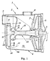
- the generally designated 1 in Fig. 1 self-priming pump unit comprises a centrifugal pump 2 and an electric motor (not shown) to their drive, the shaft 3 carries the pump impeller 4.
- the Pump 2 is installed so that the axis of rotation 5 of the pump impeller 4 runs horizontally, as shown in Fig. 1.
- centrifugal pump 2 also comprises a housing 6 a suction port 7 and a pressure port 8, both ports are usually located above the horizontal axis of rotation 5.
- the Pump impeller 4 is a guide device 9 within the housing 6 assigned, which causes the liquid delivered by the impeller first gets into the pump housing 6, from where it then over the Pressure port 8 is discharged.
- the pump impeller 4 is preceded coaxially by an ejector 10 the ejector opens into the suction mouth 11 of the pump impeller 4.
- the the other end of the ejector 10 is on the suction nozzle 7 of the pump housing 6 connected and furthermore has an inflow channel 12, which is followed in a known manner by a driving nozzle 14.
- the ejector 10 For simple manufacture of the ejector 10, it is formed in two parts. He thus consists of a first one-piece component 15, the inflow channel 12, the driving nozzle 14 and further a surrounding the driving nozzle Annulus 16, this annulus with the intake 7 of the pump housing 6 connecting suction channel 17 and also a channel-shaped Inflow extension 18 for the inflow channel 12 includes.
- This inflow extension is so long that its flow inlet 19 to in the proximity of the lower wall area 6a of the pump housing 6 is sufficient.
- the inflow channel 12 and in particular its inflow extension 18 extend the inflow channel 12 and in particular its inflow extension 18, based on the axis of rotation 5 of the pump impeller, in radial direction to the lower wall 6a of the pump housing 6.
- the inflow extension 18 also has a different course, but it is important in any case that the flow inlet 19 of the inflow extension to close to the lower one Wall area 6a of the pump housing 6, of course, while leaving it a sufficient inflow gap 20 to ensure that sufficient air-free propellant in the channel 12 and its extension 18 pressed total inflow channel can be.
- FIG. 2, 3 and 4 is a special embodiment of the first component 15 of the ejector 10 shown.
- This example preferably consists of Plastic material.
- This component has a common separate Rear wall part 23 for the inflow channel 12 and its inflow extension 18, wherein this rear wall part is removable.
- the rear wall part 23 can by means of molded, flexible link plates 24 with the remaining component 15 of the Ejector 10 may be connected. Due to the hinge plates 24, the Rear wall part 23 is not lost. Alternatively, the tabs 24 also dropped.
- the rear wall part is by means of locking means (not shown) releasably connected to the remaining component 15.
- the component 15 with inner ribs 25 for the Stabilization of the liquid flow in the annular space 16 may be provided.
- FIG. 5 shows an alternative embodiment to that in FIGS. 2, 3 and 4.
- the separate back panel 26 not removable from the rest of the component 15. Because the back panel 26 and the rest of the structure of component 15 are produced separately from one another the two parts are then connected together, preferably by a material bond, e.g. B. by welding.
- This embodiment has the advantage that the remaining structure of component 15, So with omitted rear wall part 26, casting technology because of simpler mold can be produced more cheaply compared to a component 15 with a rear wall part 26 in the intended Location.
- the previously described embodiments of the first component 15 of the Ejectors 10 have 23 or 26 due to the intended rear wall part as a rear wall boundary for the inflow channel 12 and its Inflow extension 18 has the advantage that the location and the course the end wall 6b of the pump housing 6 is disregarded are needed so that related manufacturing tolerances and shapes play no role for the pump housing 6 or freedom of design give.
- the end wall 6b of the pump housing 6 forms the rear Wall limitation for the inflow channel 12 and its inflow extension 18.
- the pump housing 6 is in length tolerated so that the end wall 6b on the rear wall-free structure 15 of the Ejector 10 is liquid-tight when the pump housing 6 with the Motor housing is connected.
- the inflow channel 12 provided with an inflow extension 18, the under Leave an entry gap 20 close to the lower wall area 6a of the pump housing 6 reaches.
Landscapes
- Engineering & Computer Science (AREA)
- Mechanical Engineering (AREA)
- General Engineering & Computer Science (AREA)
- Structures Of Non-Positive Displacement Pumps (AREA)
Applications Claiming Priority (2)
| Application Number | Priority Date | Filing Date | Title |
|---|---|---|---|
| DE19962729 | 1999-12-23 | ||
| DE1999162729 DE19962729A1 (de) | 1999-12-23 | 1999-12-23 | Selbstansaugendes Pumpenaggregat |
Publications (2)
| Publication Number | Publication Date |
|---|---|
| EP1111244A2 true EP1111244A2 (fr) | 2001-06-27 |
| EP1111244A3 EP1111244A3 (fr) | 2002-05-15 |
Family
ID=7934309
Family Applications (1)
| Application Number | Title | Priority Date | Filing Date |
|---|---|---|---|
| EP00128058A Withdrawn EP1111244A3 (fr) | 1999-12-23 | 2000-12-21 | Pompe auto-amorçante |
Country Status (2)
| Country | Link |
|---|---|
| EP (1) | EP1111244A3 (fr) |
| DE (1) | DE19962729A1 (fr) |
Cited By (1)
| Publication number | Priority date | Publication date | Assignee | Title |
|---|---|---|---|---|
| CN106351848A (zh) * | 2016-10-21 | 2017-01-25 | 杭州激湍流体科技有限公司 | 低噪音的喷射泵 |
Families Citing this family (2)
| Publication number | Priority date | Publication date | Assignee | Title |
|---|---|---|---|---|
| DE10347261A1 (de) * | 2003-10-08 | 2005-05-04 | Baer & Co Anlagentechnik Gmbh | Verfahren zum Betreiben einer Hebeeinrichtung zum Abpumpen von verunreinigten flüssigen Medien, insbesondere Kühlschmiermitteln |
| DE102006003793B8 (de) | 2005-01-25 | 2021-09-23 | Samson Regulation S.A.S | Selbstansaugendes Pumpenaggregat |
Citations (1)
| Publication number | Priority date | Publication date | Assignee | Title |
|---|---|---|---|---|
| EP0361329A1 (fr) | 1988-09-26 | 1990-04-04 | CALPEDA S.p.A. | Pompe à jet auto-amorçante avec éjecteur incorporé |
Family Cites Families (7)
| Publication number | Priority date | Publication date | Assignee | Title |
|---|---|---|---|---|
| US3063377A (en) * | 1958-12-31 | 1962-11-13 | Clayton Mark & Company | Centrifugal jet pump |
| FR1222755A (fr) * | 1959-01-22 | 1960-06-13 | Perfectionnement aux pompes centrifuges à amorçage par hydro-éjecteur | |
| FR1408233A (fr) * | 1964-06-12 | 1965-08-13 | Guinard Pompes | Perfectionnement aux pompes à amorçage automatique |
| US4820131A (en) * | 1987-09-02 | 1989-04-11 | Wayne/Scott Fetzer Company | Venturi nozzle assembly construction in a shallow well pump casing |
| DD301952A9 (de) * | 1989-08-09 | 1994-08-11 | Apollowerk Goessnitz Gmbh | Kombination von Radialradkreiselpumpe mit Strahlpumpe |
| IT229263Y1 (it) * | 1992-01-24 | 1998-07-02 | Ebara Italia | Pompa centrifuga autoadescante |
| DE9314532U1 (de) * | 1993-09-25 | 1993-12-09 | ASV Stübbe GmbH & Co KG, 32602 Vlotho | Selbstansaugende Kreiselpumpe |
-
1999
- 1999-12-23 DE DE1999162729 patent/DE19962729A1/de not_active Ceased
-
2000
- 2000-12-21 EP EP00128058A patent/EP1111244A3/fr not_active Withdrawn
Patent Citations (1)
| Publication number | Priority date | Publication date | Assignee | Title |
|---|---|---|---|---|
| EP0361329A1 (fr) | 1988-09-26 | 1990-04-04 | CALPEDA S.p.A. | Pompe à jet auto-amorçante avec éjecteur incorporé |
Cited By (1)
| Publication number | Priority date | Publication date | Assignee | Title |
|---|---|---|---|---|
| CN106351848A (zh) * | 2016-10-21 | 2017-01-25 | 杭州激湍流体科技有限公司 | 低噪音的喷射泵 |
Also Published As
| Publication number | Publication date |
|---|---|
| EP1111244A3 (fr) | 2002-05-15 |
| DE19962729A1 (de) | 2001-07-05 |
Similar Documents
| Publication | Publication Date | Title |
|---|---|---|
| DE69023699T2 (de) | Selbstansaugende Kreiselpumpe. | |
| DE4418640C2 (de) | Brennstoffpumpe für Kraftfahrzeuge | |
| DE19834341C2 (de) | Vorrichtung zur Erzeugung eines Wasser/Luftstromes in einer Whirpoolwanne | |
| DE3836748C2 (de) | Tragbare Blas/Saugvorrichtung | |
| DE8913614U1 (de) | Geschirrspülmaschine mit selbstreinigendem Filter | |
| DE68905728T2 (de) | Reinigungsapparat. | |
| EP2005005A1 (fr) | Pompe centrifuge a evacuation automatique de l'air | |
| DE10024741B4 (de) | Seitenkanalpumpe | |
| DE69900972T2 (de) | Entleerungspumpe | |
| DE4446106C2 (de) | Brennstoffpumpe für Kraftfahrzeuge | |
| EP1111244A2 (fr) | Pompe auto-amorçante | |
| DE60114583T2 (de) | Hydraulisches leistungssystem | |
| DE69707415T2 (de) | Staubsaugergehäuse mit minimierter anzahl von richtungen zum lösen aus einer gussform | |
| DE1428475A1 (de) | Vorrichtung fuer den Wasserumlauf in einer Geschirrspuelmaschine | |
| DE2064704A1 (de) | Zentrifugiereinrichtung zur Reinigung eines Betriebsmittels einer Kolbenbrennkraftmaschine. Anm | |
| DE29704753U1 (de) | Gießbares Pumpengehäuse für ein Motorpumpenaggregat zur Montage an einer ebenen Wandfläche einer Vorrichtung | |
| DE9010254U1 (de) | Geschirrspülmaschine mit einer Motorpumpe | |
| DE20004470U1 (de) | Klimaanlage | |
| EP0601220B1 (fr) | Système de pompe hydraulique, en particulier pompe de vidage de liquides | |
| DE60303788T2 (de) | Selbstansaugende Kreiselpumpe | |
| EP4280919A1 (fr) | Dispositif de préparation de boissons et distributeur automatique de boissons | |
| DE69800761T2 (de) | Elektrische Aquariumpumpe mit Filtereinheit | |
| EP0732096A2 (fr) | Buse d'injection pour bain sanitaire | |
| DE29504507U1 (de) | Gehäuse für Kreiselpumpen | |
| DE2065235C3 (de) | Zentrifugiereinrichtung zur Ausscheidung von öl aus dem Kühlwasser einer Kolbenbrennkraftmaschine |
Legal Events
| Date | Code | Title | Description |
|---|---|---|---|
| PUAI | Public reference made under article 153(3) epc to a published international application that has entered the european phase |
Free format text: ORIGINAL CODE: 0009012 |
|
| AK | Designated contracting states |
Kind code of ref document: A2 Designated state(s): AT BE CH CY DE DK ES FI FR GB GR IE IT LI LU MC NL PT SE TR |
|
| AX | Request for extension of the european patent |
Free format text: AL;LT;LV;MK;RO;SI |
|
| PUAL | Search report despatched |
Free format text: ORIGINAL CODE: 0009013 |
|
| AK | Designated contracting states |
Kind code of ref document: A3 Designated state(s): AT BE CH CY DE DK ES FI FR GB GR IE IT LI LU MC NL PT SE TR |
|
| AX | Request for extension of the european patent |
Free format text: AL;LT;LV;MK;RO;SI |
|
| 17P | Request for examination filed |
Effective date: 20020828 |
|
| 17Q | First examination report despatched |
Effective date: 20021104 |
|
| AKX | Designation fees paid |
Designated state(s): DE FR GB IT |
|
| STAA | Information on the status of an ep patent application or granted ep patent |
Free format text: STATUS: THE APPLICATION IS DEEMED TO BE WITHDRAWN |
|
| 18D | Application deemed to be withdrawn |
Effective date: 20030315 |