EP0361402A1 - Kalandervorrichtung für Papiermacherverfahren - Google Patents
Kalandervorrichtung für Papiermacherverfahren Download PDFInfo
- Publication number
- EP0361402A1 EP0361402A1 EP89117777A EP89117777A EP0361402A1 EP 0361402 A1 EP0361402 A1 EP 0361402A1 EP 89117777 A EP89117777 A EP 89117777A EP 89117777 A EP89117777 A EP 89117777A EP 0361402 A1 EP0361402 A1 EP 0361402A1
- Authority
- EP
- European Patent Office
- Prior art keywords
- roll
- paper sheet
- elastic belt
- endless elastic
- chilled
- Prior art date
- Legal status (The legal status is an assumption and is not a legal conclusion. Google has not performed a legal analysis and makes no representation as to the accuracy of the status listed.)
- Withdrawn
Links
- 238000003490 calendering Methods 0.000 title claims abstract description 50
- 238000000034 method Methods 0.000 title claims description 8
- 238000011282 treatment Methods 0.000 claims abstract description 17
- 238000001816 cooling Methods 0.000 claims description 7
- 230000037361 pathway Effects 0.000 claims description 6
- 238000010438 heat treatment Methods 0.000 claims description 5
- XLYOFNOQVPJJNP-UHFFFAOYSA-N water Substances O XLYOFNOQVPJJNP-UHFFFAOYSA-N 0.000 claims description 4
- 238000005507 spraying Methods 0.000 claims description 2
- 229920003002 synthetic resin Polymers 0.000 description 13
- 239000000057 synthetic resin Substances 0.000 description 13
- 239000010410 layer Substances 0.000 description 11
- 239000004744 fabric Substances 0.000 description 7
- 230000001788 irregular Effects 0.000 description 6
- 229920005989 resin Polymers 0.000 description 5
- 239000011347 resin Substances 0.000 description 5
- 229920002803 thermoplastic polyurethane Polymers 0.000 description 5
- 239000002344 surface layer Substances 0.000 description 4
- 230000000052 comparative effect Effects 0.000 description 3
- 238000005498 polishing Methods 0.000 description 3
- 230000003746 surface roughness Effects 0.000 description 3
- 239000004677 Nylon Substances 0.000 description 2
- 239000011248 coating agent Substances 0.000 description 2
- 239000011247 coating layer Substances 0.000 description 2
- 238000000576 coating method Methods 0.000 description 2
- 238000001035 drying Methods 0.000 description 2
- 230000000694 effects Effects 0.000 description 2
- 239000000835 fiber Substances 0.000 description 2
- 230000008642 heat stress Effects 0.000 description 2
- 239000002184 metal Substances 0.000 description 2
- 229920001778 nylon Polymers 0.000 description 2
- 238000003825 pressing Methods 0.000 description 2
- 229910000831 Steel Inorganic materials 0.000 description 1
- 230000002159 abnormal effect Effects 0.000 description 1
- 239000000654 additive Substances 0.000 description 1
- 230000000996 additive effect Effects 0.000 description 1
- 230000006835 compression Effects 0.000 description 1
- 238000007906 compression Methods 0.000 description 1
- 230000006866 deterioration Effects 0.000 description 1
- 229920001971 elastomer Polymers 0.000 description 1
- 238000007646 gravure printing Methods 0.000 description 1
- 230000012447 hatching Effects 0.000 description 1
- 230000006698 induction Effects 0.000 description 1
- 239000000203 mixture Substances 0.000 description 1
- 229920003023 plastic Polymers 0.000 description 1
- 239000004033 plastic Substances 0.000 description 1
- 230000000717 retained effect Effects 0.000 description 1
- 239000010959 steel Substances 0.000 description 1
- 238000004381 surface treatment Methods 0.000 description 1
- 238000009941 weaving Methods 0.000 description 1
Images


Classifications
-
- D—TEXTILES; PAPER
- D21—PAPER-MAKING; PRODUCTION OF CELLULOSE
- D21G—CALENDERS; ACCESSORIES FOR PAPER-MAKING MACHINES
- D21G1/00—Calenders; Smoothing apparatus
- D21G1/0066—Calenders; Smoothing apparatus using a special calendering belt
-
- D—TEXTILES; PAPER
- D21—PAPER-MAKING; PRODUCTION OF CELLULOSE
- D21G—CALENDERS; ACCESSORIES FOR PAPER-MAKING MACHINES
- D21G1/00—Calenders; Smoothing apparatus
Definitions
- the present invention relates to a calendering apparatus for a paper making process. More particularly, the present invention relates to a calendering apparatus used for improving the surface properties of a paper sheet by applying a smoothness, a gloss or the like to a surface of the paper sheet.
- calendering apparatuses are used in a paper making process; typical of which are a machine calender, i.e., a chilled nip calender, and a supercalender.
- the machine calender is arranged directly down stream of a drying part in a paper making machine, i.e., in an on-line arrangement to improve the surface properties of the paper sheet, and includes at least a nip formed by two chilled rolls made of a steel.
- the chilled roll is arranged in a vertical direction alternately with an elastic roll, and the supercalender is used as an apparatus independent of the paper making machine, i.e., in an off-line arrangement.
- the supercalender applies several nips to the paper under a high pressure, and is used to produce a paper sheet having a superior smoothness, such as a gravure printing paper.
- a soft nip calender apparatus including a nip formed by the elastic roll and the chilled roll as a pair has been developed, and is used in an on-line arrangement like the machine calender.
- the supercalender is usually driven off-line at a low speed, due to the need to take into consideration for deterioration of the elastic roll when operated under a high pressure and multiple nips conditions. Therefore, in a calendering treatment of the paper sheet, the machine calender or the soft nip calender are most widely used.
- a change in the surface of the paper sheet caused by a treatment with the machine calender is illustrated by a cross section in a widthwise direction perpendicular to a running direction of the paper sheet in Fig. 1, and a change caused by the soft nip calender is illustrated in Fig. 2, in the same manner as in Fig. 1.
- FIG. 1(A) and Fig. 2(A) A cross section in the widthwise direction of the paper sheet before the calendering treatment is illustrated in Fig. 1(A) and Fig. 2(A) respectively.
- a thickness of the paper sheet just after a drying process is irregular; i.e., the paper sheet 10 has thick portions 10a and thin portions 10b.
- a cross sectional shape of the paper sheet 10 after being nipped by two chilled rolls 50 of the machine calender is illustrated in Fig. 1(B), and a cross sectional shape of the paper sheet 10 after being nipped by a chilled roll 50 and an elastic roll 51 of the soft nip calender is illustrated in Fig. 2(B).
- a surface layer of the thick portion 10a of the paper sheet 10 is made smooth by a pressing action of the chilled roll, but since a surface layer of the thin portion 10b of the paper sheet 10 does not come into contact with the chilled roll 50, small untreated portions remain on the paper sheet 10.
- a surface 11a opposite to the chilled roll 50 of the paper sheet 10 is made flat by the even cylindrical surface of the chilled roll 50, and irregular shape of the surface 11a before the calendering operation is transferred to and duplicated at another surface 11b of the paper sheet 10.
- the elastic roll 51 is deformed in accordance with the duplicated irregular shape of the surface 11b, due to its own elasticity, and accordingly, the surface 11a is made and remains smooth during the first stage of the calendering treatment and has a required gloss.
- the paper sheet 10 is then again treated by another calendering unit in which the chilled roll and the elastic roll are arranged in a reversed relationship, and thus the surface 11b is made flat. Accordingly, both surfaces 11a and 11b are then smooth and have the desired gloss.
- FIGs. 1(C) and 2(C) The cross sectional shapes of the paper sheets after receiving the calendering treatment are illustrated in Figs. 1(C) and 2(C).
- the paper sheet treated with the machine calender has substantially the some thickness but the density and surface properties thereof are irregular.
- the paper sheet treated with the soft nip calender has an irregular thickness but the density is constant, and thus the surface properties are improved in that the surface smoothness is uniform.
- Portions 12 to which the calendering treatment of the surface layer of the paper sheet in Fig. 1(C) and Fig. 2(C) is applied are shown by hatching.
- the surface of the paper sheet is made smoother by the soft nip calender, and therefore, the printability of the paper sheet treated with the soft nip calender is superior to that of the paper sheet treated with the machine calender.
- the soft nip calender has the following drawbacks.
- First the elastic roll of the soft nip calender is constructed by a layer of a synthetic resin having a high thermal resistance covering a metallic roll.
- the synthetic resin layer has an extremely low conductivity and a large coefficient of thermal expansion compared with those of the surface of the metal roll.
- the calendering treatment should not be carried out at a high temperature and a high pressure, as this will shorten the working life of the elastic roll.
- the condition of the elastic roll must be closely observed at all times.
- the use of the elastic roll provide a superior effect, when the calendering apparatus including the elastic roll is continuously used in an actual industrial operation, often the use of the elastic roll does not provide a satisfactory calendering treatment capable of producing a paper sheet having a desired quality.
- An object of the present invention is to solve the above problem caused by the elastic roll and to provide a calendering apparatus capable of producing a paper sheet having the same level of quality as that of a paper sheet treated by a calendering apparatus including the elastic roll.
- a calendering apparatus for a paper making process including at least a nip constituted by two rolls, wherein the two rolls are a chilled roll and a backing roll, and an endless elastic belt having a longer length than a circumferential length of the backing roll is arranged over a nip portion of the backing roll so that the endless elastic belt is moved by a rotation of the backing roll and nips a paper sheet with the chilled roll at the nip portion thereof.
- the calendering apparatus in accordance with the present invention can be applied to a paper sheet without a coating layer on a surface thereof and a paper sheet with a coating layer on a surface thereof.
- the later paper sheet includes an art paper, a coated paper, or a recording paper such as a heat sensitive recording paper, a pressure sensitive recording paper, and an ink jet recording paper.
- a surface of the paper sheet (hereinafter referred to as a front surface) is pressed by the chilled roll, and another surface of the paper sheet (hereinafter referred to as a back surface) is pressed by the endless elastic belt.
- any irregularities of the front surface i.e., concave portions and convex portion of the front surface, are made uniform, and these irregularities of the front surface are transferred to the back surface, whereby the irregularities of the front surface of the paper sheet are added to the irregularities of the back surface.
- This amplified irregularity of the back surface is completely observed by an elasticity of the endless elastic belt, and accordingly, the chilled roll can apply uniform a smoothness and gloss to the front surface not having irregularities.
- a partial heat build-up may be generated in the endless elastic belt upon applying the surface treatment, but since the endless elastic belt has a relatively long length compared with a circumferential length of the backing roll, i.e., the endless elastic belt has a portion not in contact with the nipping portion, a heated portion of the endless elastic belt is sequentially dissipated or cooled when not in contact with the chilled roll, whereby heat stress in the endless elastic belt is reduced and the elasticity of the endless elastic is recovered. This portion is then circulated until in contact with the nipping portion. Therefore, according to the present invention, an abnormal high temperature and a deformation of the endless elastic belt is prevented.
- a cooling device is arranged at a position near to a pathway of the endless elastic belt.
- a chilled roll 1 is rotatably mounted on a calender frame 13 through a fitting arm 14.
- a backing roll 2 arranged in a mutually opposing state in a vertical direction at a position below the chilled roll 1 is mounted on a movable fitting arm 15 having end pivotably arranged on the calender frame 13.
- the backing roll 2 is provided with a device for rotating the backing roll 2 (not shown).
- a drive portion of a lift up device 4 is fixed to a free end of the movable fitting arm 15, whereby the movable fitting arm 15 is swung up about the pivoting point by a pressure of the lift up device 4, and the backing roll 2 is brought into contact with the chilled roll 1 under pressure.
- An endless elastic belt 3 is arranged such that portion of the endless elastic belt 3 covers a nipping portion N or the backing roll 2 while pressing the against the backing roll, and the elastic belt 3 runs over the backing roll 2, retaining rolls 7a, 7b, 7c and 7d, a stretching roll 8, and a guide roll 9.
- the chilled roll 1 includes a heating means 13 heated by a heating medium, such as steam, hot water, electric induction or the like. Further, a cooling device 6 such as an air shower, a water spraying device or the like is arranged at a position near to a pathway of the endless elastic belt 3, so that a cooling action is applied toward the heated endless elastic belt 33 and the heated endless elastic belt 33 is suitably cooled. Sheet rolls 17a, 17b are arranged to supply the paper sheet 10 between the chilled roll 1 and the endless elastic belt 3.
- a heating medium such as steam, hot water, electric induction or the like.
- a cooling device 6 such as an air shower, a water spraying device or the like is arranged at a position near to a pathway of the endless elastic belt 3, so that a cooling action is applied toward the heated endless elastic belt 33 and the heated endless elastic belt 33 is suitably cooled.
- Sheet rolls 17a, 17b are arranged to supply the paper sheet 10 between the chilled roll 1 and the endless elastic belt 3.
- the surface in contact with the chilled roll 1 of the paper sheet i.e., the front surface thereof, is made smooth compared with the surface in contact with the endless elastic roll 3, i.e., the back surface thereof.
- a second set of rolls in which the components are arranged in reverse to those of the first set of rolls, and the paper sheet is passed through the second set of rolls after being treated by the first set of rolls.
- the second set rolls is arranged at the side of the calender frame 11 from which the paper sheet is output.
- the endless elastic belt 23 is in contact with the paper sheet 10 from above, and the backing roll 22 over which the endless elastic belt 23 is arranged is mounted on a movable fitting arm 34 mounted at a upper position of a pathway of the paper sheet 10.
- the backing roll 22 is connected with a device for rotating the backing roll 22 (not shown).
- the endless elastic belt 23 is arranged over the backing roll 22, retaining rolls 27a, 27b, 27c and 27d, a stretching roll 28, and a guide roll 29, is pressed against a surface of the backing roll 2 under a tension adjustable by the stretching roll 28.
- a cooling device 26 is mounted at a position near to the pathway of the endless elastic belt 23.
- the chilled roll 34 including a heating means 36 is pivotally arranged on a calender frame 13 via a movable fitting arm 34, and can be brought into contact with the backing roll 22, under pressure, by an upward operation of a lift up device 24.
- the front surface of the paper sheet 10 is treated by the first set of rolls and the back surface of the paper sheet is treated by the second set of rolls.
- the lift up devices 4 and 24 lift corresponding movable fitting devices 15 or 25 upward, respectively, and accordingly the backing roll 2 is pressed against the chilled roll 1 and the chilled roll 21 is pressed against the backing roll 22. Since the endless elastic belt 3 and 23 are arranged over the backing rolls and 22, respectively, the paper sheet 10 is pressed between the endless elastic belts 3 and 23 and the chilled rolls 1 and 21, to smooth the surfaces thereof.
- the backing roll 2 and 22 are metallic rolls, and the chilled roll per se may be used as the backing roll or a crown controlled roll may be used to adjust a thickness of the paper sheet.
- the chilled roll has no elasticity on a surface thereof, and the heating devices 16 and 36 can be omitted depending on the quality of the paper sheet to be manufactured.
- the structure of the endless elastic belts 3.23 is not limited, and the endless elastic belt is usually formed by adhering or coating a synthetic resin having a heat resistance, a pressure resistance, and a good compression elasticity, to a fabric made of fibers having a heat resistance. Also, preferably the surface of the endless elastic belt is polished to a surface roughness of between 1 ⁇ m and 20 ⁇ m.
- a preferable range of the elasticity of the synthetic resin is a shore hardness D of between 50 and 75. The hardness may be adjusted in accordance with the type of resin used, or a type or a quantity of an additive added to the resin.
- the thickness of the synthetic resin layer of the belt can be made thinner, to control heat build-up and prolong the life of the elastic belt, but a surface treated with such an endless elastic belt will probably have a surface similar to a surface treated with a chilled nip calender. Conversely, if the thickness of the synthetic resin layer of the belt is made thicker, the surface of the paper sheet is improved, but if the thickness of the belt is too thick, the durability of the belt is poor. Therefore, a preferable thickness of the synthetic resin layer is between 1 mm and 10 mm.
- An endless elastic belt having a synthetic resin layer on both side thereof is suitable for a polishing operation, because the synthetic resin layer opposite to the synthetic resin layer to be polished can be firmly held on a polishing table during the polishing operation. If the endless elastic belt having a sufficient strength can be obtained by only the synthetic resin layer, it is not necessary to use the base fabric. Further, it is possible to use a belt made of a rubber, a metal or the like in stead of the base fabric.
- a rotating or drive apparatus may be arranged at either one of the pair of rolls or at the endless elastic belt.
- a rotating device is provided at the pair of rolls and a drive device at the endless elastic belt, to lower the load imposed on the endless elastic belt at a start of the operation of the apparatus.
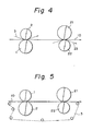
- Figures 4 - 9 illustrates various examples of the arrangement of endless elastic belt.
- the second set of rolls includes a chilled roll 21, a backing roll 22, and an endless elastic belt 23 arranged in reverse to the arrangement of a first set of rolls including a chilled roll 1, a backing roll 2 and an endless elastic belt 3.
- both surfaces of a paper sheet 10 are treated in the same way as described with reference to Fig. 3.
- one side surface of a paper sheet is treated twice by two chilled rolls of two sets of rolls, to provide a smoother surface.
- one endless elastic belt is used for both sets of rolls and is used as a guide for the paper sheet.
- four nips are use to twice treat each surface. Namely, two backing rolls 2a, and 2b are arranged with a chilled roll 1, and an endless elastic belt 3 is arranged over the two backing rolls 2a and 2b and the chilled roll 1, and two backing rolls 22a and 22b are arranged with the chilled roll 21 and two endless empty belts 23a and 23b are independently arranged over the two backing roll 22a and 22b.
- a paper sheet 10 pretreated by a machine calender 4 is treated by a set of rolls having the same arrangement as that illustrated in an upper portion in Fig. 7, to treat the same surface of the paper sheet with two nips.
- two of rolls including four nips are arranged with a chilled roll 1, to treat both surfaces of the paper sheet 10.
- Three endless elastic belts 3a, 3b, and 3c are used for a chilled roll 1 to make the four nips in an upper portion of this arrangement, and the four nips are formed between the chilled roll 21 and an endless elastic belt 23 in a lower portion thereof.
- the calendering apparatus in accordance with the present invention is combined with a conventional machine calender.
- two backing roll 2a and 2b and two endless elastic belts 3a, 3b are alternately arranged over two chilled rolls 1a and 1b, in place of an elastic roll used in the conventional machine calender, and a paper sheet 10 dried by a dryer 41 is supplied in an on-line fashion.
- the conventional machine calender can be easily converted to an calendering device in accordance with the present invention.
- Examples 1, and 2 of the present invention were produced by the calendering apparatus having the constitution illustrated in Fig. 3, by changing a shore hardness of the endless elastic belt.
- the composition of the endless elastic belt was as follows:
- Warp Yarn i.e., a yarn parallel to a running direction of the belt: Nylon monofilament having a diameter of 0.43 mm
- Weft Yarn Nylon monofilament having a diameter of 0.52 mm
- Weaving pattern Doube face fabric Thickness: 1.8 mm
- a urethane resin was coated on a surface of the base fabric by an extruder so that the urethane resin is permeated the base fabric, and the surface was polished. Thickness of the surface layer of the urethane resin: 1.67 mm Shore hardness D of the surface of the urethane resin: 70 (Example 1) 55 (Example 2) Roughness of the polished surface of the urethane resin: 16 ⁇ m
- the calendering treatments of Examples 1, 2 and Comparative Example were performed by treating a free sheet having a weight per unit area of 64 g/m2 with two nips at a line pressure of 56 kg/cm and a roll temperature of 70°C, and a running speed of the paper of 1000 m/sec.
- the paper sheets treated with the calendering apparatus in accordance with the present invention have a superior smoothness and gloss, and differences between the smoothness and the gloss of the front surface denoted as F in Table 1 and the back surface denoted as W in Table 1 are small.
Landscapes
- Paper (AREA)
Applications Claiming Priority (2)
| Application Number | Priority Date | Filing Date | Title |
|---|---|---|---|
| JP63245524A JP2819535B2 (ja) | 1988-09-29 | 1988-09-29 | 製紙用カレンダ装置 |
| JP245524/88 | 1988-09-29 |
Publications (1)
| Publication Number | Publication Date |
|---|---|
| EP0361402A1 true EP0361402A1 (de) | 1990-04-04 |
Family
ID=17134967
Family Applications (1)
| Application Number | Title | Priority Date | Filing Date |
|---|---|---|---|
| EP89117777A Withdrawn EP0361402A1 (de) | 1988-09-29 | 1989-09-26 | Kalandervorrichtung für Papiermacherverfahren |
Country Status (3)
| Country | Link |
|---|---|
| EP (1) | EP0361402A1 (de) |
| JP (1) | JP2819535B2 (de) |
| FI (1) | FI92849C (de) |
Cited By (9)
| Publication number | Priority date | Publication date | Assignee | Title |
|---|---|---|---|---|
| EP0451449A1 (de) * | 1990-04-09 | 1991-10-16 | Sulzer-Escher Wyss Gmbh | Verfahren zum Glätten einer beidseitig gestrichenen Papier- oder Kartonbahn |
| US5400707A (en) * | 1992-10-09 | 1995-03-28 | Champion International Corporation | Apparatus for finishing a continuous sheet of paper |
| WO1999023305A1 (en) * | 1997-10-31 | 1999-05-14 | Beloit Technologies, Inc. | Soft nip calender |
| US6182564B1 (en) | 1998-06-24 | 2001-02-06 | Voith Sulzer Papiertechnik Patent Gmbh | Apparatus and process for the smoothing of a material web |
| US6203307B1 (en) * | 1997-08-28 | 2001-03-20 | Champion International Corporation | System for finishing surface of a web of paper having an improved continuous finishing belt |
| US6332953B1 (en) | 1998-10-02 | 2001-12-25 | International Paper Company | Paper product having enhanced printing properties and related method of manufacture |
| EP1467019A3 (de) * | 2003-04-11 | 2005-02-09 | Voith Paper Patent GmbH | Anordnung zum Behandeln einer Papier- oder Kartonbahn |
| US6946186B2 (en) | 2002-08-24 | 2005-09-20 | International Paper Co. | Uncoated facestock for adhesive-backed labels |
| CN1625629B (zh) * | 2002-01-29 | 2012-06-27 | 梅特索纸业有限公司 | 加工涂布或非涂布纤维幅的加工装置 |
Families Citing this family (2)
| Publication number | Priority date | Publication date | Assignee | Title |
|---|---|---|---|---|
| JPH0519399U (ja) * | 1991-08-23 | 1993-03-09 | 石川島播磨重工業株式会社 | カレンダ装置 |
| JP2904464B2 (ja) * | 1992-12-29 | 1999-06-14 | 市川毛織 株式会社 | 製紙カレンダ用弾性ベルト |
Citations (2)
| Publication number | Priority date | Publication date | Assignee | Title |
|---|---|---|---|---|
| GB968938A (en) * | 1961-07-11 | 1964-09-09 | Kuesters Eduard | Improvements in calendering rollers |
| FR2588293A1 (fr) * | 1985-10-04 | 1987-04-10 | Waertsilae Oy Ab | Ensemble de calandrage, tel que par exemple une supercalandre |
Family Cites Families (4)
| Publication number | Priority date | Publication date | Assignee | Title |
|---|---|---|---|---|
| JPS416163Y1 (de) * | 1964-02-28 | 1966-03-30 | ||
| JPS5137523B2 (de) * | 1972-05-29 | 1976-10-16 | ||
| JPS5352709A (en) * | 1976-10-20 | 1978-05-13 | Fuji Photo Film Co Ltd | Super calender apparatus |
| JPS61148917U (de) * | 1985-03-08 | 1986-09-13 |
-
1988
- 1988-09-29 JP JP63245524A patent/JP2819535B2/ja not_active Expired - Lifetime
-
1989
- 1989-09-26 EP EP89117777A patent/EP0361402A1/de not_active Withdrawn
- 1989-09-28 FI FI894610A patent/FI92849C/fi active IP Right Grant
Patent Citations (2)
| Publication number | Priority date | Publication date | Assignee | Title |
|---|---|---|---|---|
| GB968938A (en) * | 1961-07-11 | 1964-09-09 | Kuesters Eduard | Improvements in calendering rollers |
| FR2588293A1 (fr) * | 1985-10-04 | 1987-04-10 | Waertsilae Oy Ab | Ensemble de calandrage, tel que par exemple une supercalandre |
Cited By (13)
| Publication number | Priority date | Publication date | Assignee | Title |
|---|---|---|---|---|
| EP0451449A1 (de) * | 1990-04-09 | 1991-10-16 | Sulzer-Escher Wyss Gmbh | Verfahren zum Glätten einer beidseitig gestrichenen Papier- oder Kartonbahn |
| US5400707A (en) * | 1992-10-09 | 1995-03-28 | Champion International Corporation | Apparatus for finishing a continuous sheet of paper |
| US5546856A (en) * | 1992-10-09 | 1996-08-20 | Neider; Thomas M. | Method for finishing a continuous sheet of paper |
| US5694837A (en) * | 1992-10-09 | 1997-12-09 | Champion International Corporation | Apparatus for finsihing a continuous sheet of paper |
| US6203307B1 (en) * | 1997-08-28 | 2001-03-20 | Champion International Corporation | System for finishing surface of a web of paper having an improved continuous finishing belt |
| WO1999023305A1 (en) * | 1997-10-31 | 1999-05-14 | Beloit Technologies, Inc. | Soft nip calender |
| US6182564B1 (en) | 1998-06-24 | 2001-02-06 | Voith Sulzer Papiertechnik Patent Gmbh | Apparatus and process for the smoothing of a material web |
| US6332953B1 (en) | 1998-10-02 | 2001-12-25 | International Paper Company | Paper product having enhanced printing properties and related method of manufacture |
| CN1625629B (zh) * | 2002-01-29 | 2012-06-27 | 梅特索纸业有限公司 | 加工涂布或非涂布纤维幅的加工装置 |
| US6946186B2 (en) | 2002-08-24 | 2005-09-20 | International Paper Co. | Uncoated facestock for adhesive-backed labels |
| US7666495B2 (en) | 2002-08-24 | 2010-02-23 | International Paper Company | Uncoated facestock for adhesive-backed labels |
| US7794567B2 (en) | 2002-08-24 | 2010-09-14 | International Paper Co. | Uncoated facestock for adhesive-backed labels |
| EP1467019A3 (de) * | 2003-04-11 | 2005-02-09 | Voith Paper Patent GmbH | Anordnung zum Behandeln einer Papier- oder Kartonbahn |
Also Published As
| Publication number | Publication date |
|---|---|
| FI92849B (fi) | 1994-09-30 |
| FI92849C (fi) | 1995-01-10 |
| FI894610L (fi) | 1990-03-30 |
| JPH0291296A (ja) | 1990-03-30 |
| FI894610A0 (fi) | 1989-09-28 |
| JP2819535B2 (ja) | 1998-10-30 |
Similar Documents
| Publication | Publication Date | Title |
|---|---|---|
| US5251551A (en) | Calendering apparatus for paper making process | |
| US5836242A (en) | Calendering system including a belt having an adaptable web-contacting surface | |
| EP0617165B1 (de) | Verfahren zum Kalandern einer Papierbahn und ein Kalander zur Durchführung des Verfahrens | |
| CA2285301C (en) | Calendering method and a calender that makes use of the method | |
| CA2285291C (en) | Calendering method and a calender that makes use of the method | |
| EP0361402A1 (de) | Kalandervorrichtung für Papiermacherverfahren | |
| WO2000017446A1 (en) | Method and apparatus for finishing paperboard to achieve improved smoothness and bulk | |
| EP0672785B1 (de) | Kalandervorrichtung für Papier | |
| US5876565A (en) | Press section with an equalizing nip for compensating for elongation of a paper web | |
| FI111090B (fi) | Liikkuvan rainan puristusjärjestely | |
| US3254593A (en) | Gloss calender drive system and method | |
| CN113002120A (zh) | 一种织物阻燃防水涂层复合设备 | |
| CA2284748C (en) | Multilayer lineboard having improved printing properties and related method of manufacture | |
| JP2800908B2 (ja) | 紙シートのカレンダ処理方法 | |
| EP1208266B1 (de) | Verfahren und anordnung zur oberflächenbehandlung einer papier- oder kartonbahn | |
| JP2904464B2 (ja) | 製紙カレンダ用弾性ベルト | |
| EP0907798A1 (de) | Verfahren und vorrichtung zur herstellung von beschichtetem dünnpapier | |
| JP2003227089A (ja) | 紙のカレンダ処理装置及びカレンダ処理方法 | |
| JP2906403B2 (ja) | 製紙用カレンダ装置及びカレンダ処理方法 | |
| EP0966566A1 (de) | Verfahren und vorrichtung zur behandlung einer faserbahn | |
| US6007921A (en) | Continuous finishing belt capable of finishing surface of a web of paper | |
| US6475342B1 (en) | Method of and arrangement for treating a fiber web | |
| JPH06313296A (ja) | キャストコーテッド紙の製造方法 |
Legal Events
| Date | Code | Title | Description |
|---|---|---|---|
| PUAI | Public reference made under article 153(3) epc to a published international application that has entered the european phase |
Free format text: ORIGINAL CODE: 0009012 |
|
| AK | Designated contracting states |
Kind code of ref document: A1 Designated state(s): DE FR SE |
|
| 17P | Request for examination filed |
Effective date: 19900920 |
|
| 17Q | First examination report despatched |
Effective date: 19920410 |
|
| STAA | Information on the status of an ep patent application or granted ep patent |
Free format text: STATUS: THE APPLICATION IS DEEMED TO BE WITHDRAWN |
|
| 18D | Application deemed to be withdrawn |
Effective date: 19921021 |