EP0361426B1 - Bildaufzeichnungsgerät - Google Patents
Bildaufzeichnungsgerät Download PDFInfo
- Publication number
- EP0361426B1 EP0361426B1 EP89117823A EP89117823A EP0361426B1 EP 0361426 B1 EP0361426 B1 EP 0361426B1 EP 89117823 A EP89117823 A EP 89117823A EP 89117823 A EP89117823 A EP 89117823A EP 0361426 B1 EP0361426 B1 EP 0361426B1
- Authority
- EP
- European Patent Office
- Prior art keywords
- opening
- closing member
- closing
- locking means
- feed
- Prior art date
- Legal status (The legal status is an assumption and is not a legal conclusion. Google has not performed a legal analysis and makes no representation as to the accuracy of the status listed.)
- Expired - Lifetime
Links
- 239000000463 material Substances 0.000 claims description 53
- 230000000994 depressogenic effect Effects 0.000 claims description 17
- 238000011144 upstream manufacturing Methods 0.000 claims description 8
- 210000000078 claw Anatomy 0.000 description 14
- 238000004873 anchoring Methods 0.000 description 12
- 238000000034 method Methods 0.000 description 7
- 230000003287 optical effect Effects 0.000 description 3
- 238000010276 construction Methods 0.000 description 2
- 238000003825 pressing Methods 0.000 description 2
- 229920003002 synthetic resin Polymers 0.000 description 2
- 239000000057 synthetic resin Substances 0.000 description 2
- 238000004140 cleaning Methods 0.000 description 1
- 230000000881 depressing effect Effects 0.000 description 1
- 230000000694 effects Effects 0.000 description 1
- 230000005489 elastic deformation Effects 0.000 description 1
- 238000003780 insertion Methods 0.000 description 1
- 230000002093 peripheral effect Effects 0.000 description 1
Images






Classifications
-
- G—PHYSICS
- G03—PHOTOGRAPHY; CINEMATOGRAPHY; ANALOGOUS TECHNIQUES USING WAVES OTHER THAN OPTICAL WAVES; ELECTROGRAPHY; HOLOGRAPHY
- G03G—ELECTROGRAPHY; ELECTROPHOTOGRAPHY; MAGNETOGRAPHY
- G03G15/00—Apparatus for electrographic processes using a charge pattern
- G03G15/65—Apparatus which relate to the handling of copy material
- G03G15/6552—Means for discharging uncollated sheet copy material, e.g. discharging rollers, exit trays
-
- B—PERFORMING OPERATIONS; TRANSPORTING
- B65—CONVEYING; PACKING; STORING; HANDLING THIN OR FILAMENTARY MATERIAL
- B65H—HANDLING THIN OR FILAMENTARY MATERIAL, e.g. SHEETS, WEBS, CABLES
- B65H7/00—Controlling article feeding, separating, pile-advancing, or associated apparatus, to take account of incorrect feeding, absence of articles, or presence of faulty articles
- B65H7/02—Controlling article feeding, separating, pile-advancing, or associated apparatus, to take account of incorrect feeding, absence of articles, or presence of faulty articles by feelers or detectors
-
- B—PERFORMING OPERATIONS; TRANSPORTING
- B65—CONVEYING; PACKING; STORING; HANDLING THIN OR FILAMENTARY MATERIAL
- B65H—HANDLING THIN OR FILAMENTARY MATERIAL, e.g. SHEETS, WEBS, CABLES
- B65H85/00—Recirculating articles, i.e. feeding each article to, and delivering it from, the same machine work-station more than once
-
- B—PERFORMING OPERATIONS; TRANSPORTING
- B65—CONVEYING; PACKING; STORING; HANDLING THIN OR FILAMENTARY MATERIAL
- B65H—HANDLING THIN OR FILAMENTARY MATERIAL, e.g. SHEETS, WEBS, CABLES
- B65H9/00—Registering, e.g. orientating, articles; Devices therefor
- B65H9/04—Fixed or adjustable stops or gauges
-
- G—PHYSICS
- G03—PHOTOGRAPHY; CINEMATOGRAPHY; ANALOGOUS TECHNIQUES USING WAVES OTHER THAN OPTICAL WAVES; ELECTROGRAPHY; HOLOGRAPHY
- G03G—ELECTROGRAPHY; ELECTROPHOTOGRAPHY; MAGNETOGRAPHY
- G03G15/00—Apparatus for electrographic processes using a charge pattern
- G03G15/22—Apparatus for electrographic processes using a charge pattern involving the combination of more than one step according to groups G03G13/02 - G03G13/20
- G03G15/23—Apparatus for electrographic processes using a charge pattern involving the combination of more than one step according to groups G03G13/02 - G03G13/20 specially adapted for copying both sides of an original or for copying on both sides of a recording or image-receiving material
- G03G15/231—Arrangements for copying on both sides of a recording or image-receiving material
- G03G15/232—Arrangements for copying on both sides of a recording or image-receiving material using a single reusable electrographic recording member
- G03G15/234—Arrangements for copying on both sides of a recording or image-receiving material using a single reusable electrographic recording member by inverting and refeeding the image receiving material with an image on one face to the recording member to transfer a second image on its second face, e.g. by using a duplex tray; Details of duplex trays or inverters
-
- G—PHYSICS
- G03—PHOTOGRAPHY; CINEMATOGRAPHY; ANALOGOUS TECHNIQUES USING WAVES OTHER THAN OPTICAL WAVES; ELECTROGRAPHY; HOLOGRAPHY
- G03G—ELECTROGRAPHY; ELECTROPHOTOGRAPHY; MAGNETOGRAPHY
- G03G15/00—Apparatus for electrographic processes using a charge pattern
- G03G15/65—Apparatus which relate to the handling of copy material
- G03G15/6555—Handling of sheet copy material taking place in a specific part of the copy material feeding path
- G03G15/6558—Feeding path after the copy sheet preparation and up to the transfer point, e.g. registering; Deskewing; Correct timing of sheet feeding to the transfer point
- G03G15/6561—Feeding path after the copy sheet preparation and up to the transfer point, e.g. registering; Deskewing; Correct timing of sheet feeding to the transfer point for sheet registration
- G03G15/6564—Feeding path after the copy sheet preparation and up to the transfer point, e.g. registering; Deskewing; Correct timing of sheet feeding to the transfer point for sheet registration with correct timing of sheet feeding
-
- G—PHYSICS
- G03—PHOTOGRAPHY; CINEMATOGRAPHY; ANALOGOUS TECHNIQUES USING WAVES OTHER THAN OPTICAL WAVES; ELECTROGRAPHY; HOLOGRAPHY
- G03G—ELECTROGRAPHY; ELECTROPHOTOGRAPHY; MAGNETOGRAPHY
- G03G15/00—Apparatus for electrographic processes using a charge pattern
- G03G15/65—Apparatus which relate to the handling of copy material
- G03G15/6555—Handling of sheet copy material taking place in a specific part of the copy material feeding path
- G03G15/6558—Feeding path after the copy sheet preparation and up to the transfer point, e.g. registering; Deskewing; Correct timing of sheet feeding to the transfer point
- G03G15/6567—Feeding path after the copy sheet preparation and up to the transfer point, e.g. registering; Deskewing; Correct timing of sheet feeding to the transfer point for deskewing or aligning
-
- G—PHYSICS
- G03—PHOTOGRAPHY; CINEMATOGRAPHY; ANALOGOUS TECHNIQUES USING WAVES OTHER THAN OPTICAL WAVES; ELECTROGRAPHY; HOLOGRAPHY
- G03G—ELECTROGRAPHY; ELECTROPHOTOGRAPHY; MAGNETOGRAPHY
- G03G21/00—Arrangements not provided for by groups G03G13/00 - G03G19/00, e.g. cleaning, elimination of residual charge
- G03G21/16—Mechanical means for facilitating the maintenance of the apparatus, e.g. modular arrangements
-
- B—PERFORMING OPERATIONS; TRANSPORTING
- B65—CONVEYING; PACKING; STORING; HANDLING THIN OR FILAMENTARY MATERIAL
- B65H—HANDLING THIN OR FILAMENTARY MATERIAL, e.g. SHEETS, WEBS, CABLES
- B65H2301/00—Handling processes for sheets or webs
- B65H2301/30—Orientation, displacement, position of the handled material
- B65H2301/33—Modifying, selecting, changing orientation
- B65H2301/333—Inverting
- B65H2301/3331—Involving forward reverse transporting means
- B65H2301/33312—Involving forward reverse transporting means forward reverse rollers pairs
-
- B—PERFORMING OPERATIONS; TRANSPORTING
- B65—CONVEYING; PACKING; STORING; HANDLING THIN OR FILAMENTARY MATERIAL
- B65H—HANDLING THIN OR FILAMENTARY MATERIAL, e.g. SHEETS, WEBS, CABLES
- B65H2402/00—Constructional details of the handling apparatus
- B65H2402/10—Modular constructions, e.g. using preformed elements or profiles
-
- B—PERFORMING OPERATIONS; TRANSPORTING
- B65—CONVEYING; PACKING; STORING; HANDLING THIN OR FILAMENTARY MATERIAL
- B65H—HANDLING THIN OR FILAMENTARY MATERIAL, e.g. SHEETS, WEBS, CABLES
- B65H2404/00—Parts for transporting or guiding the handled material
- B65H2404/60—Other elements in face contact with handled material
- B65H2404/61—Longitudinally-extending strips, tubes, plates, or wires
- B65H2404/611—Longitudinally-extending strips, tubes, plates, or wires arranged to form a channel
- B65H2404/6111—Longitudinally-extending strips, tubes, plates, or wires arranged to form a channel and shaped for curvilinear transport path
-
- B—PERFORMING OPERATIONS; TRANSPORTING
- B65—CONVEYING; PACKING; STORING; HANDLING THIN OR FILAMENTARY MATERIAL
- B65H—HANDLING THIN OR FILAMENTARY MATERIAL, e.g. SHEETS, WEBS, CABLES
- B65H2405/00—Parts for holding the handled material
- B65H2405/30—Other features of supports for sheets
- B65H2405/32—Supports for sheets partially insertable - extractable, e.g. upon sliding movement, drawer
- B65H2405/324—Supports for sheets partially insertable - extractable, e.g. upon sliding movement, drawer between operative position and non operative position
-
- B—PERFORMING OPERATIONS; TRANSPORTING
- B65—CONVEYING; PACKING; STORING; HANDLING THIN OR FILAMENTARY MATERIAL
- B65H—HANDLING THIN OR FILAMENTARY MATERIAL, e.g. SHEETS, WEBS, CABLES
- B65H2511/00—Dimensions; Position; Numbers; Identification; Occurrences
- B65H2511/20—Location in space
-
- B—PERFORMING OPERATIONS; TRANSPORTING
- B65—CONVEYING; PACKING; STORING; HANDLING THIN OR FILAMENTARY MATERIAL
- B65H—HANDLING THIN OR FILAMENTARY MATERIAL, e.g. SHEETS, WEBS, CABLES
- B65H2511/00—Dimensions; Position; Numbers; Identification; Occurrences
- B65H2511/50—Occurence
- B65H2511/51—Presence
-
- B—PERFORMING OPERATIONS; TRANSPORTING
- B65—CONVEYING; PACKING; STORING; HANDLING THIN OR FILAMENTARY MATERIAL
- B65H—HANDLING THIN OR FILAMENTARY MATERIAL, e.g. SHEETS, WEBS, CABLES
- B65H2513/00—Dynamic entities; Timing aspects
- B65H2513/40—Movement
- B65H2513/41—Direction of movement
-
- B—PERFORMING OPERATIONS; TRANSPORTING
- B65—CONVEYING; PACKING; STORING; HANDLING THIN OR FILAMENTARY MATERIAL
- B65H—HANDLING THIN OR FILAMENTARY MATERIAL, e.g. SHEETS, WEBS, CABLES
- B65H2553/00—Sensing or detecting means
- B65H2553/60—Details of intermediate means between the sensing means and the element to be sensed
- B65H2553/61—Mechanical means, e.g. contact arms
-
- G—PHYSICS
- G03—PHOTOGRAPHY; CINEMATOGRAPHY; ANALOGOUS TECHNIQUES USING WAVES OTHER THAN OPTICAL WAVES; ELECTROGRAPHY; HOLOGRAPHY
- G03G—ELECTROGRAPHY; ELECTROPHOTOGRAPHY; MAGNETOGRAPHY
- G03G15/00—Apparatus for electrographic processes using a charge pattern
- G03G15/22—Apparatus for electrographic processes using a charge pattern involving the combination of more than one step according to groups G03G13/02 - G03G13/20
- G03G15/23—Apparatus for electrographic processes using a charge pattern involving the combination of more than one step according to groups G03G13/02 - G03G13/20 specially adapted for copying both sides of an original or for copying on both sides of a recording or image-receiving material
- G03G15/231—Arrangements for copying on both sides of a recording or image-receiving material
- G03G15/232—Arrangements for copying on both sides of a recording or image-receiving material using a single reusable electrographic recording member
- G03G15/234—Arrangements for copying on both sides of a recording or image-receiving material using a single reusable electrographic recording member by inverting and refeeding the image receiving material with an image on one face to the recording member to transfer a second image on its second face, e.g. by using a duplex tray; Details of duplex trays or inverters
- G03G15/235—Arrangements for copying on both sides of a recording or image-receiving material using a single reusable electrographic recording member by inverting and refeeding the image receiving material with an image on one face to the recording member to transfer a second image on its second face, e.g. by using a duplex tray; Details of duplex trays or inverters the image receiving member being preconditioned before transferring the second image, e.g. decurled, or the second image being formed with different operating parameters, e.g. a different fixing temperature
-
- G—PHYSICS
- G03—PHOTOGRAPHY; CINEMATOGRAPHY; ANALOGOUS TECHNIQUES USING WAVES OTHER THAN OPTICAL WAVES; ELECTROGRAPHY; HOLOGRAPHY
- G03G—ELECTROGRAPHY; ELECTROPHOTOGRAPHY; MAGNETOGRAPHY
- G03G2215/00—Apparatus for electrophotographic processes
- G03G2215/00362—Apparatus for electrophotographic processes relating to the copy medium handling
- G03G2215/00367—The feeding path segment where particular handling of the copy medium occurs, segments being adjacent and non-overlapping. Each segment is identified by the most downstream point in the segment, so that for instance the segment labelled "Fixing device" is referring to the path between the "Transfer device" and the "Fixing device"
- G03G2215/00379—Copy medium holder
- G03G2215/00383—Cassette
-
- G—PHYSICS
- G03—PHOTOGRAPHY; CINEMATOGRAPHY; ANALOGOUS TECHNIQUES USING WAVES OTHER THAN OPTICAL WAVES; ELECTROGRAPHY; HOLOGRAPHY
- G03G—ELECTROGRAPHY; ELECTROPHOTOGRAPHY; MAGNETOGRAPHY
- G03G2215/00—Apparatus for electrophotographic processes
- G03G2215/00362—Apparatus for electrophotographic processes relating to the copy medium handling
- G03G2215/00367—The feeding path segment where particular handling of the copy medium occurs, segments being adjacent and non-overlapping. Each segment is identified by the most downstream point in the segment, so that for instance the segment labelled "Fixing device" is referring to the path between the "Transfer device" and the "Fixing device"
- G03G2215/00396—Pick-up device
-
- G—PHYSICS
- G03—PHOTOGRAPHY; CINEMATOGRAPHY; ANALOGOUS TECHNIQUES USING WAVES OTHER THAN OPTICAL WAVES; ELECTROGRAPHY; HOLOGRAPHY
- G03G—ELECTROGRAPHY; ELECTROPHOTOGRAPHY; MAGNETOGRAPHY
- G03G2215/00—Apparatus for electrophotographic processes
- G03G2215/00362—Apparatus for electrophotographic processes relating to the copy medium handling
- G03G2215/00367—The feeding path segment where particular handling of the copy medium occurs, segments being adjacent and non-overlapping. Each segment is identified by the most downstream point in the segment, so that for instance the segment labelled "Fixing device" is referring to the path between the "Transfer device" and the "Fixing device"
- G03G2215/00405—Registration device
-
- G—PHYSICS
- G03—PHOTOGRAPHY; CINEMATOGRAPHY; ANALOGOUS TECHNIQUES USING WAVES OTHER THAN OPTICAL WAVES; ELECTROGRAPHY; HOLOGRAPHY
- G03G—ELECTROGRAPHY; ELECTROPHOTOGRAPHY; MAGNETOGRAPHY
- G03G2215/00—Apparatus for electrophotographic processes
- G03G2215/00362—Apparatus for electrophotographic processes relating to the copy medium handling
- G03G2215/00367—The feeding path segment where particular handling of the copy medium occurs, segments being adjacent and non-overlapping. Each segment is identified by the most downstream point in the segment, so that for instance the segment labelled "Fixing device" is referring to the path between the "Transfer device" and the "Fixing device"
- G03G2215/00417—Post-fixing device
- G03G2215/00421—Discharging tray, e.g. devices stabilising the quality of the copy medium, postfixing-treatment, inverting, sorting
-
- G—PHYSICS
- G03—PHOTOGRAPHY; CINEMATOGRAPHY; ANALOGOUS TECHNIQUES USING WAVES OTHER THAN OPTICAL WAVES; ELECTROGRAPHY; HOLOGRAPHY
- G03G—ELECTROGRAPHY; ELECTROPHOTOGRAPHY; MAGNETOGRAPHY
- G03G2215/00—Apparatus for electrophotographic processes
- G03G2215/00362—Apparatus for electrophotographic processes relating to the copy medium handling
- G03G2215/00367—The feeding path segment where particular handling of the copy medium occurs, segments being adjacent and non-overlapping. Each segment is identified by the most downstream point in the segment, so that for instance the segment labelled "Fixing device" is referring to the path between the "Transfer device" and the "Fixing device"
- G03G2215/00417—Post-fixing device
- G03G2215/0043—Refeeding path
-
- G—PHYSICS
- G03—PHOTOGRAPHY; CINEMATOGRAPHY; ANALOGOUS TECHNIQUES USING WAVES OTHER THAN OPTICAL WAVES; ELECTROGRAPHY; HOLOGRAPHY
- G03G—ELECTROGRAPHY; ELECTROPHOTOGRAPHY; MAGNETOGRAPHY
- G03G2215/00—Apparatus for electrophotographic processes
- G03G2215/00362—Apparatus for electrophotographic processes relating to the copy medium handling
- G03G2215/00535—Stable handling of copy medium
- G03G2215/0054—Detachable element of feed path
-
- G—PHYSICS
- G03—PHOTOGRAPHY; CINEMATOGRAPHY; ANALOGOUS TECHNIQUES USING WAVES OTHER THAN OPTICAL WAVES; ELECTROGRAPHY; HOLOGRAPHY
- G03G—ELECTROGRAPHY; ELECTROPHOTOGRAPHY; MAGNETOGRAPHY
- G03G2215/00—Apparatus for electrophotographic processes
- G03G2215/00362—Apparatus for electrophotographic processes relating to the copy medium handling
- G03G2215/00535—Stable handling of copy medium
- G03G2215/00544—Openable part of feed path
-
- G—PHYSICS
- G03—PHOTOGRAPHY; CINEMATOGRAPHY; ANALOGOUS TECHNIQUES USING WAVES OTHER THAN OPTICAL WAVES; ELECTROGRAPHY; HOLOGRAPHY
- G03G—ELECTROGRAPHY; ELECTROPHOTOGRAPHY; MAGNETOGRAPHY
- G03G2221/00—Processes not provided for by group G03G2215/00, e.g. cleaning or residual charge elimination
- G03G2221/16—Mechanical means for facilitating the maintenance of the apparatus, e.g. modular arrangements and complete machine concepts
- G03G2221/1651—Mechanical means for facilitating the maintenance of the apparatus, e.g. modular arrangements and complete machine concepts for connecting the different parts
- G03G2221/1654—Locks and means for positioning or alignment
-
- G—PHYSICS
- G03—PHOTOGRAPHY; CINEMATOGRAPHY; ANALOGOUS TECHNIQUES USING WAVES OTHER THAN OPTICAL WAVES; ELECTROGRAPHY; HOLOGRAPHY
- G03G—ELECTROGRAPHY; ELECTROPHOTOGRAPHY; MAGNETOGRAPHY
- G03G2221/00—Processes not provided for by group G03G2215/00, e.g. cleaning or residual charge elimination
- G03G2221/16—Mechanical means for facilitating the maintenance of the apparatus, e.g. modular arrangements and complete machine concepts
- G03G2221/1672—Paper handling
-
- G—PHYSICS
- G03—PHOTOGRAPHY; CINEMATOGRAPHY; ANALOGOUS TECHNIQUES USING WAVES OTHER THAN OPTICAL WAVES; ELECTROGRAPHY; HOLOGRAPHY
- G03G—ELECTROGRAPHY; ELECTROPHOTOGRAPHY; MAGNETOGRAPHY
- G03G2221/00—Processes not provided for by group G03G2215/00, e.g. cleaning or residual charge elimination
- G03G2221/16—Mechanical means for facilitating the maintenance of the apparatus, e.g. modular arrangements and complete machine concepts
- G03G2221/1678—Frame structures
- G03G2221/169—Structural door designs
-
- G—PHYSICS
- G03—PHOTOGRAPHY; CINEMATOGRAPHY; ANALOGOUS TECHNIQUES USING WAVES OTHER THAN OPTICAL WAVES; ELECTROGRAPHY; HOLOGRAPHY
- G03G—ELECTROGRAPHY; ELECTROPHOTOGRAPHY; MAGNETOGRAPHY
- G03G2221/00—Processes not provided for by group G03G2215/00, e.g. cleaning or residual charge elimination
- G03G2221/16—Mechanical means for facilitating the maintenance of the apparatus, e.g. modular arrangements and complete machine concepts
- G03G2221/1696—Mechanical means for facilitating the maintenance of the apparatus, e.g. modular arrangements and complete machine concepts for auxiliary devices, e.g. add-on modules
Definitions
- This invention relates to an image-forming machine such as an electrostatic copying machine or a laser beam printer.
- Image-forming machines such as an electrostatic copying machine have been in widespread commercial use.
- a second object of the invention is to provide an excellent image-forming machine in which whether an opening-closing member defining a feed passage is held at a closing position can be ascertained easily and accurately.
- a third object of this invention is to provide an excellent image-forming machine in which locking means for locking an opening-closing member into a closing position can be held accurately in a locked state by a relatively simple structure.
- a fourth object of this invention is to provide an excellent image-forming machine in which noises produced at the time of delivering a sheet material can be suppressed.
- a fifth object of this invention is to provide an excellent image-forming machine in which folding of a sheet material which is liable to occur when it is delivered from feed means can be prevented.
- a sixth object of this invention is to provide an excellent image-forming machine in which the structure relating to an opening-closing member is simple.
- a seventh object of this invention is to provide an excellent image-forming machine in which an opening-closing member can be accurately held at a closing position.
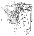
- the illustrated laser beam printer includes a nearly rectangular paralellpipedal main body 2 which has a so-called shell-type, i.e. vertically divisible, structure comprised of a lower frame member 4 and an upper frame member 6 mounted on the lower frame member 4 through a shaft member 5 (constituting a central axis extending perpendicularly to the sheet surface in Figure 1) so that it is free to pivot between an opening position (not shown) and a closing potition (the position shown in Figure 1).
- shell-type i.e. vertically divisible, structure comprised of a lower frame member 4 and an upper frame member 6 mounted on the lower frame member 4 through a shaft member 5 (constituting a central axis extending perpendicularly to the sheet surface in Figure 1) so that it is free to pivot between an opening position (not shown) and a closing potition (the position shown in Figure 1).
- a process unit shown by reference numeral 8 is disposed in the upper frame member 6 of the main body 2.
- the illustrated process unit 8 is provided with a unit frame 10 detachably mounted on the upper frame member 6, and a rotating drum 12 is rotatably mounted on the unit frame 10.
- An electrostatographic material is disposed on the peripheral surface of the rotating drum 12.
- Around the rotating drum 12 which is to be rotated in the direction shown by an arrow 14 are disposed a charging corona discharger 16, a developing device 18, a transfer corona discharger 20 and a cleaning device 22.
- An optical unit shown by numeral 34 is disposed in the upper space of the upper frame member 6, i.e. the space above the process unit 8.
- the optical unit 34 includes a box-like unit housing 36.
- a laser light source (not shown)
- the laser light source irradiates laser light based on an image information outputted from a computer, for example, onto the rotating polygon mirror 38.
- the laser light reflected from the rotating polygon mirror 38 is reflected by the first reflecting mirror 40 and the second reflecting mirror 42, passes through the lens 44 and is projected onto the surface of the rotating drum 12 in a projecting zone 46, as shown by a one-dot chain line in Figure 1.
- a conveying means 50 for conveying a sheet material which may be plain paper through a transfer zone 48 existing between the rotating drum 12 and the transfer corona discharger 20.
- the illustrated conveying means 50 is provided with a conveying roller pair 52, a guide member 54, a guide member 56 and a fixing roller pair 58, and defines a conveying passage 51 extrending nearly in a straight line from the nipping site 60 of the conveying roller pair 52 to the nipping site 62 of the fixing roller pair 58.
- a hand-insertion feed means 64 is provided at the right end of the conveying passage 51, and below the conveying means 50, namely in the lower portion of the lower frame member 4, a first feed means 66 and a second feed means 68 are disposed.
- the first feed means 66 is comprised of a receiving portion 78 defined by the bottom portion of the main body 2, i.e. the bottom portion of the lower frame member 4, a cassette 82 detachably loaded into the receiving section 78 through an opening 80 formed in the left surface of the main body 2, and feed means 84 disposed above the receiving portion 78. Sheet materials are loaded into the cassette 82.
- the second supply means 68 positioned above the first supply means 66 is comprised of a receiving portion 88 defined in the upper portion of the lower frame member 4, a cassette 92 loaded detachably into the receiving portion 88 through an opening 90 formed in the left surface of the main body 2, and feed means 94 disposed above the receiving portion 88, and sheet materials are loaded into the cassette 92.
- the feed means 94 is rotated in the direction of arrow, the uppermost sheet material is delivered from the cassette 92, and fed to the conveying passage through the second feed passage 96.
- a receiving plate 98 constituting a first receiving means is disposed in the left end portion in Figure 1 of the main body 2.
- the illustrated receiving plate 98 is comprised of a first piate 100 having a slightly concave upper surface (the upper surface in the state shown by a two-dot chain line in Figure 1) and a second plate 102 extending nearly in a straight line.
- a first discharge passage 106 is provided between the receiving plate 98 and the conveying passage 51.
- the illustrated first discharge passage 106 is defined by a guide member 108 and a first discharge roller pair 110.
- the second receiving means is defined by an inclined upper surface 112a in the upper wall 112 of the main body 2.
- an auxiliary receiving member 114 which is free to pivot between a receiving position extending following the inclined upper surface 112a and a storage position above the inclined upper surface 112a.
- a second discharge passage 116 is provided between the second receiving member and the first discharge passage 106.
- the second discharge passage 116 is defined by the receiving plate 98 at the storage position (particularly, the right surface in Figure 1 of the second plate 102 in the storage state), a plurality of guide ribs 120 (one of which is shown in Figure 1) provided on the inner surface of the wall 118 and a second discharge roller pair 122.
- the operation of the laser beam printer described above will be described below in a general manner. While the rotating drum 12 is rotated in the direction of arrow 14, the charging corona discharger 16 charges the electrostatographic material of the rotating drum 12 to a specific polarity. Then, in the projecting zone 46, laser light from the laser light source (not shown) in the optical unit 34 is projected onto the electrostatographic material. As a result, a latent electrostatic image corresponding to the image information is formed on the surface of the electrostatographic material.
- first feed passage 66 for conducting the sheet material delivered from the first feed means 66 to the conveying passage
- second feed passage 96 for conducting the sheet material delivered from the second feed means 68 to the conveying passage
- a greater portion of the first feed passage 86 is defined by a first opening-closing member 124 and a second opening-closing member 126, and a greater portion of the second feed passage 96 is defined by the second opening-closing member 126.
- the downstream portion of the first feed passage 86 and the downstream portion of the second feed passage 96 are associated, and the associated portion of the two passages is connected to the upstream end of the conveying passage 51.
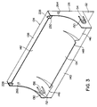
- the illustrated first opening-closing member 124 has a pair of end walls 128 and 130 spaced from each other a predetermined distance, and between these end walls 128 and 130 are provided an outside wall 132, an inside wall 134, a bottom wall 136 and an upper wall 138 (see Figure 1 also).
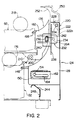
- the inside wall 134 has a substantially flat lower portion 140 and an upper portion 142 extending upwardly in an arcuate curved shape, and as can be seen from Figures 1 and 2, the inside surface of the upper portion 142 of the inside wall 134 defines one side of the first feed passage 86, i.e. its right side in Figure 1.
- a plurality of guide ribs 144 in spaced-apart relationship in the widthwise direction are provided integrally on the inside surface (the surface acting as a guiding surface) of the upper portion 142 of the inside wall 134 (in Figure 3, the guide ribs 144 are omitted).
- Contact-preventing depressed portions 146 are defined in both end portions in the widthwise direction of the upper portion 142 of the inside wall 134.
- the central part in the widthwise direction of the upper portion 142 of the inside wall 134 extends downwardly with a relatively large curving from the nearly central part in the vertical direction.
- both end portions in the widthwise direction of the upper portion 142 of the inside wall 134 extend downwardly with a relatively small curving from its nearly central part in the vertical direction.
- the contact-preventing depressed portions 146 are provided in both ends of the upper portion 142.
- an introduction protrusion 148 protruding into the receiving portion 78 of the first supply means 66 are provided integrally, and nearly horizontally in Figures 1 and 2, in the upstream end of the central part, in the widthwise direction, of the upper portion 142.
- the introduction protrusion 148 is provided over substantially the entire width of the part between the contact-preventing depressed portions 146 in the upper portion 142 of the inside wall 134, and the guide ribs 144 provided on the upper portion 142 of the inside wall 134 extend to the introduction protrusion 148.
- Supporting portions 150 and 152 are formed integrally in the end walls 128 and 130 of the first opening-closing member 124 by removing them locally in a nearly U shape, and outwardly projecting pins 154 and 156 are provided at the end parts of the supporting portions 150 and 152.
- the lower frame member 4 has a pair of vertical base plates 158 and 160 ( Figure 5) which are disposed in spaced-apart relationship perpendicularly to the sheet surface in Figure 1 and vertically in Figure 5.
- Supporting plate pieces 162 are provided in the inside surfaces of the vertical base plates 158 and 160 ( Figure 2 shows only one supporting plate 162 disposed in the inside surface of the base plate 158), and an elongate hole 164 extending to the right nearly horizontally in Figures 1 and 2 is formed in each supporting plate piece 162 ( Figure 2 shows one hole 164 formed in one supporting plate piece 162 and Figure 1 shows the other hole 164 in the supporting plate piece 162 not shown in the drawings).
- One end portion (the left inside end portion in Figures 1 and 2) extends while curving slightly upwardly.
- the pins 154 and 156 provided in the first opening-closing member 124 are detachably received in the pair of elongate holes 164.
- the first opening-closing member 124 may be formed of a synthetic resin, and by pressing the base parts of the supporting portions 150 and 152, it can be elastically deformed inwardly. This elastic deformation permits detachment of the pair of pins 154 and 156 from the corresponding holes 164.
- the first opening-closing member 124 is free to move between an operating position at which the pins 154 and 156 are positioned respectively at the end portions of the holes 164 (the position shown in Figures 1 and 2 and by a two-dot chain line 124 in Figure 7) and a removed position at which the pins 154 and 156 are positioned in the other end portions of the holes 164 (the position in Figure 7 by a solid line and in Figure 8) along these holes 164, and also free to pivot between a closing position at which it defines one side of the first feed passage 86 (the position shown in Figures 1 and 2 and by the two-dot chain line 124 in Figure 7) and an opening position at which it permits opening of the first feed passage 86 (the position shown in Figure 7 by a solid line and in Figure 8).
- the contact-preventing depressed portion 146 and the introduction protrusion 148 in the first opening-closing member 124 and the first feed means 66 are further constructed as shown below in the illustrated embodiment.
- the cassette 82 is equipped with a box-like cassette body 166 having an open top, which is adapted to be mounted detachably between the pair of vertical base plates 158 and 160 of the lower frame member 4 through the opening 80.
- a carrying plate 168 is disposed within the cassette body 166, and a biasing spring (not shown) is interposed between the carrying plate 168 and the bottom wall of the cassette body 166.
- the rear end portion of the carrying plate 168 is mounted on the cassette body via a pin 170 so that the plate 168 is free to pivot.
- a stack of sheet materials which may be plain paper are placed on the carrying plate 168.
- Claw members 172 ( Figure 5) for preventing overlapping feed of the sheet materials are disposed at both corners of the front end portion of the cassette body 166.
- the pair of claw members 172 can slightly move up and down and act on the two corners of the leading end of the sheet materials received in the cassette body.
- the feed means 84 is provided with a shaft member 174 mounted rotatably between and across the pair of vertical base plates of the lower frame member 4.
- a pair of feed rollers 176 are mounted on the shaft member 174 in an axially spaced-apart relationship.
- the first feed means 66 and the contact-preventing depressed portion 146 are arranged in the positional relationship shown in Figure 5. Specifically, the contact-preventing depressed portion 146 is disposed opposite to the claw member 172 and its vicinity in the cassette 82.
- the contact-preventing depressed portion 146 is disposed opposite to the claw member 172 and its vicinity in the cassette 82.
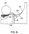
- that part of the sheet material which exists between the feed roller 176 and the claw members 172 bends upwardly, leaves the claw members 172 and jumps forwardly (shown by the two-dot chain line in Figure 6). The sheet material then continues to advance by the action of the feed roller 176.
- the corners of the leading end of the sheet material (particularly, that part which exists between the feed roller 176 and the claw members 172) will contact the inside wall 134 of the first opening-closing member 124 and is likely to fold downwardly.
- the provision of the contact-preventing depressed portions 146 in both widthwise end portions of the inside wall 134 serves to accurately prevent the corner portions of the leading end of the sheet material from contacting the inside wall 134 upon delivery from the cassette 82.
- the side of the contact-preventing depressed portion 146 is such that the leading end of the sheet material does not contact the inside wall 134. A sufficient effect can be obtained, for example, when the height h in Figure 6 is about 15 mm.
- the feed means 84 is composed of the pair of feed rollers 176, it is preferable to provide one contact-preventing depressed portion 146 opposite to the part between one feed roller 176 and the claw members 172 and the other contact-preventing depressed portion 146 opposite to the part between the other feed roller 176 and the claw members 172.
- the first feed means 66 and the introduction protrusion 148 are arranged in the positional relationship shown in Figure 1, 5 and 6.
- the introduction protrusion 148 is constructed such that its end 148 projects to a point above the front wall 178 of the cassette body 166 loaded in the cassette-receiving section 78, and its protruding end surface defines nearly the same plane with the inside surface of the front wall 178 (in relation to this structure, a cut 180 corresponding to the introduction protrusion 148 is formed in the upper end of the front wall 178 of the cassette body 166).
- the projecting end surface of the introduction protrusion 148 restricts the leading ends of the sheet materials received in the cassette body 166 and the inside surface of the front wall 178 of the cassette body 166.
- the introduction protrusion 148 for conducting the sheet material delivered from the cassette 82 to the first feed passage 86 is not provided, and in this case, a space exists between the front wall 178 of the cassette body 166 loaded in the cassette-receiving section 78 and the inside wall 134 of the first opening-closing member 124.
- the stiffness of the sheet material itself causes its trailing end to touch the upstream end of the inside wall 134, and consequently, produce noises.
- the introduction protrusion 148 is provided as described above, there is substantially no space between the front wall 178 of the cassette body 166 and the inside wall 134 of the opening-closing member 124 at a part where the introduction protrusion 148 exists.
- the sheet material delivered from the cassette body 166 is therefore guided by the upper surface of the introduction protrusion 148 and conducted to the first feed passage 86, and its trailing end is accurately prevented from contacting the upstream end of the inside wall 134.
- the feed means 84 consists of the pair of feed rollers 176, that part of the sheet material which exists between the feed rollers 176 is fed stably by the feed rollers 176. It is preferable therefore to provide the introduction protrusion 148 in correspondence to that part of the sheet material which is stably delivered, namely that part which exists between the pair of feed rollers 176.
- the illustrated second opening-closing member 126 has a pair of spaced end walls 182 and 184 which are slightly larger than the pair of end walls 128 and 130 in the first opening-closing member 124, and a lower wall 186 extending downwardly in a straight line and an upper arcuate wall 188 extending while curving upwardly are disposed between the pair of end walls 182 and 184.
- the outside surfaces (the right surfaces in Figures 1 and 2) of the lower wall 186 and the upper arcuate wall 188 define the left side in Figure 1 of the first feed passage 86
- the inside surface (the left surface in Figures 1 and 2) of the upper arcuate wall 188 defines the right side in Figure 1 of the second feed passage 96.
- a plurality of guide ribs 190 are provided in spaced-apart relationship on the outside surfaces of the lower wall 186 and the upper arcuate wall 188 in the widthwise direction (perpendicularly to the sheet surface in Figures 1 and 2), and a plurality of guide ribs 192 are provided at widthwise intervals on the inside surface of the upper arcuate wall 188. Furthermore, a plurality of contacting ribs 194 are provided on the inside surface of the lower wall 186 at widthwise intervals. In Figure 4, the guide ribs 190 and 192 and the contacting ribs 194 are omitted.
- a contact-preventing depressed portion 196 is defined in both widthwise end portions of the upper arcuate wall 188, and an introduction protrusion 198 slightly projecting into the cassette receiving section 88 of the second supply means 68 in the widthwise central part of the upper arcuate wall 188 which acts as a guiding surface of the second feed passage 96, as in the first opening-closing member 124.
- the widthwise central part of the upper arcuate wall 188 extends downwardly while curving relatively greatly, and the widthwise end portions of the upper arcuate wall 188 extend inclinedly downwardly in a nearly straight line.
- the introduction protrusion 198 is provided over substantially the entire width of a part between the contact-preventing depressed portions 196 in the upper arcuate wall 188, and extends nearly horizontally to the left in Figures 1 and 2 towards the cassette receiving section 88.
- the guide ribs 192 extend to the introduction protrusion 198.
- Supporting protrusions 200 and 202 projecting to the left in Figures 1 and 2 are integrally provided in the lower end portions of the end walls 182 and 184 of the second opening-closing member 126, and pins 204 and 206 projecting outwardly are provided in the supporting protrusions 200 and 202.
- a plate 208 defining the under surface of the cassette receiving section 88 is set between the pair of vertical base plates 158 and 160 ( Figure 5) of the lower frame member 4. To the undersurface of the plate 208 are secured a pair of supporting brackets (Figure 2 shows a front bracket 210 and Figure 1, a rear bracket 210).
- the pins 204 and 206 in the second opening-closing member 126 are detachably and pivotally mounted on the pair of supporting brackets 210.
- the second opening-closing member 126 can also be formed of a synthetic resin.
- the second opening-closing member 126 is free to pivot between a closing position (the position shown in Figures 1 and 2) at which its inside surface defines one side of the second feed passage 96 and its outside surface defines the other surface of the first feed passage 86) and an opening position (the position shown in Figure 8) at which it opens the second feed passage 96.
- the second feed means 68 is of substantially the same construction as the first feed means 66.
- the cassette 92 is provided with a box-like cassette body 212 having an open top, and is detachably loaded through the opening 90 into the cassette receiving section defined by the pair of vertical base plate 158 and 160 and the plate 208.
- a carrying plate 214 which is free to pivot vertically with its rear end portion as a fulcrum.
- a biasing spring (not shown) is interposed between the carrying plate 214 and a bottom wall of the cassette body 212.
- the feed means 94 is equipped with a shaft member 216 rotatably mounted between, and across, the vertical base plates 158 and 160.
- a pair of feed rollers 218 (only one of which is shown in Figures 1 and 2) are mounted on the shaft member 216 in axially spaced relationship.
- the contact-preventing depressed portions 196 and the introduction protrusion 198 in the second feed means 68 and the second opening-closing member 126 are arranged in substantially the same positional relationship as the contact-preventing depressed portions 146 and the introduction protrusion 148 in the first feed means 86 and the first opening-closing member 124, and they operate in substantially the same manner. Accordingly, a detailed description of the structure and operation of these members 196 and 198 is omitted herein.
- first locking means 220 are provided in order to releasably lock the first opening-closing member 124 into the closing position while it is held at the operating position.
- the first locking means 220 are disposed respectively at the widthwise end portions of the upper end portions of the first opening-closing member 124.
- Each of the first locking means 220 is provided with an anchoring member 222, and a shaft portion 224 provided in the anchoring member 222 is pivotally mounted on the inside surface of the end wall of the first opening-closing member 124 (on the inside surface of the end wall 128 in the case of one first locking means 220, and on the inside surface of the end wall 130 in the case of the other first locking means 220).
- One end portion 222a of the anchoring member 222 acts as an operating portion, and is operated in the direction shown by an arrow 226 ( Figure 1) when the anchoring member 222 is held in the released state.
- a claw portion 228 is provided in the other end portion of the anchoring member 222, and can projects upwardly through an opening 230 formed in the upper wall 138 and the inside wall 134 of the first opening-closing member 124.
- the anchoring member 222 further has provided therein a biasing spring (not shown) for biasing the anchoring member 222 in a direction opposite to the direction of arrow 226.
- the anchoring member 222 is held at a locked position (the position shown in Figures 1 and 2 and by a two-dot chain line 222 in Figure 7) when the action of the biasing spring causes the claw portion 228 to contact the opening end of the upper wall 138.
- second locking means 232 are provided in order to releasably lock the second opening-closing member 126 into the above position.
- the second locking means 232 are provided at the widthwise end portions of the second opening-closing member 126, and have operative projecting portions 234 extending to the right in Figures 1 and 2 (one operative projecting portion 234 is provided in the end wall 182, and the other operative projecting portion 234, in the end wall 184).
- An outwardly projecting locking pin 236 is provided in the end portion of each of the operative projecting portions 234.
- recesses are formed in the end walls 182 and 184 so as to enable the operative projecting portions 234 to be elastically deformed inwardly to a relatively large extent.
- a pair of plate pieces 240 (one of them is shown in Figure 2) are disposed in the inside surface of a right outside wall 238 ( Figure 2) in the main body 2 of the machine in correspondence to the operative projecting portions 234.
- Each of the plate pieces 240 has formed therein a hole 242 capable of releasably receiving the pin 236 of the operative projecting portion 234.
- a biasing spring 244 which can be formed of, for example, a plate spring is disposed below the first opening-closing member 124.
- the biasing spring 244 is secured to a fixing piece 248 attached to a bottom wall 246 in the main body 2 of the machine. Its arcuately curving end portion acts on the bottom wall 136 of the first opening-closing 124 to bias the first opening-closing member 124 clockwise in Figures 1 and 2 about the pins 154 and 156 as a center.
- the first opening-closing member 124 and the second opening-closing member 126 are kept in the state shown in Figures 1 and 2. Specifically, the anchoring members 222 in the first locking means 220 are held in the locked position, and the claw portions 228 projecting upwardly through the openings 230 engage the lower end portion of a cover member 250. As a result, the first opening-closing member 124 is locked releasably into the closing position while it is at the operative position. In this closed state, the first opening-closing member 124 is biased clockwise by the action of the biasing spring 244, and thus elastically held at the closing position.
- the pins 236 in the second locking means 232 are detachably received in the holes 242 of the plate pieces 240, and thus, the second opening-closing member 126 is locked into the closing position.
- a greater portion of the first feed passage 86 is defined by the inside surface of the first opening-closing member 124 and the outside surface of the second opening-closing member 126, as shown in Figure 1.
- a sheet material delivered from the first feed means 66 passes between the first opening-closing member 124 and the second opening-closing member 126 and further through guide ribs 252 formed in the inside surface of the cover member 250 and a feed roller 254, and is fed to the upstream end of the conveying passage.
- Most of one side of the second feed passage 96 is defined by the inside surface of the second opening-closing member 126, and a sheet material delivered from the second feed means 68 is guided by the second opening-closing member 126, passes between the guide ribs 252 and the feed roller 254, and is fed to the upstream end of the conveying passage 51.
- the illustrated embodiment has the following characteristic features in relation to the feeding of the sheet material from the first feed means 66.
- the sheet material delivered from the first feed means 66 acts so as to bias the first opening-closing member 124 clockwise in Figure 1 about the pins 154 and 156 as a center, or in other words, so as to cause the first opening-closing member 124 to be held at the above opening and closing positions. Accordingly, the first opening-closing member 124 accurately conducts the sheet material delivered from the first feed means 66 between the guide ribs 252 and the feed roller 254 without being displaced from the closing position by the sheet material.
- the anchoring members 222 of the first locking means 220 are pivoted in the direction of arrow 226 through the openings formed in the outside wall 132 of the first opening-closing member 124, as shown in Figure 7.
- the anchoring members 222 are brought to the unlocked position shown in Figure 7 from the locking position, and the claw portions 228 are substantially received within the first opening-closing member 124 and disengaged from the cover member 250, to permit movement of the first opening-closing member 124.
- the first opening-closing member 124 is pivoted in the direction shown by an arrow 258 while it is moved in the direction shown by an arrow 256.
- the pins 154 and 156 move to the right in Figure 7 within and along the holes 164 of the supporting plate pieces 162, and as the pins 154 and 156 abut with the other ends of the holes 164, the first opening-closing member 124 is held at the operating position past the position shown by the two-dot chain line 124A in Figure 7.
- the first opening-closing member 124 is turned in the direction of arrow 258, it pivots clockwise around the pins 154 and 156 as a center.
- the pins 154 and 156 can be detached from the holes 162 and 164 by elastically deforming the supporting members 150 and 152 elastically, and the first opening-closing member 124 can be detached from the main body 2 of the machine.
- the first opening-closing member 124 is constructed such that it is free to move between the operating position and the removed position, and when the first feed passage 86 is opened, the first opening-closing member 124 is moved to the removed position and held at the opening position.
- the first feed passage can be opened to a greater extent than when the first opening-closing member is constructed merely such that it is free to pivot between the opening position and the closing position, and it is much easier to remove the sheet material in the event of paper jamming.
- the biasing spring biases the first opening-closing member 124 clockwise toward the opening position, as can be seen from Figure 7, the first opening-closing member 124 can be easily pivoted toward the opening position by the biasing action of the biasing spring 244.
- the biasing spring 244 also acts as a supporting guide during the movement of the first opening-closing member 124 between the operating position and the removed position, the first opening-closing member 124 can be smoothly moved in the direction of arrow 256 and in a direction opposite to it.
- the operative protrusions 234 of the second locking means 232 are pressed inwardly through openings formed by positioning the first opening-closing member 124 at the above operating position.
- the operating protrusions 234 are elastically deformed inwardly from the locking position and the pins 236 are detached from the holes 242 of the plate pieces 240 to allow the second opening-closing member 126 to be free to pivot. direction shown by an arrow 262 ( Figure 8) while it is elastically deformed inwardly.
- the first feed passage 86 can be opened to a greater extent than in the prior art, and in relation to it, by pivoting the second opening-closing member 126 to a relatively large extent, it comes into contact with the first opening-closing member 124. Accordingly, the second feed passage 96 can also be opened to a great extent.
- the second opening-closing member 126 is pivoted in a direction opposite to the direction of arrow 262 to the above closing position, and then, the pins 236 in the second locking means 232 are brought into engagement with the holes 242 of the plate pieces 240.
- the first opening-closing member 124 is pivoted in the opposite direction shown by arrow 258 while it is moved in a direction opposite to the direction of arrow 256.
- the first opening-closing member 124 is held at the closing position while it is at the operative position. Thereafter, the claw portions 228 of the anchoring members 222 of the first locking means 220 are engaged with the cover member 250.
- the illustrated embodiment is further constructed as shown below in relation to the second locking means 232. Firstly, it is so constructed that when the second locking means 232 are in the locking condition and then the first opening-closing member 124 is locked into the closing position, it is virtually impossible to cancel the locking of the second locking means 232.
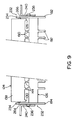
- outwardly projecting nearly triangular operative protrusions 264 and 266 are further provided in the outside surfaces of the end walls 128 and 130 of the first opening-closing member 124 in the illustrated embodiment. These operative protrusions 264 and 266 are disposed in correspondence to, and constructed so as to act on, the operative protrusions 234 in the second locking means 232.
- the pair of end walls 128 and 130 of the first opening-closing member 124 are situated inwardly of the pair of end walls 182 and 184 of the second opening-closing member 126 as shown in Figure 9.
- the operative protrusion 264 provided in the end wall 128 acts on the inside surface of the operating protrusion 234 provided in one second locking means 232
- the operating protrusion 266 provided in the other end wall 130 acts on the inside surface of the operating protrusion 234 in the other second locking means 232.
- the first opening-closing member 124 is designed such that when the second opening-closing member 126 is not locked in the closing position by the second locking means 232, it is virtually impossible to pivot the first opening-closing member 124 to the closing position at the operating position.
- the pins 236 provided in the operating protrusions 234 of the second locking means 232 is positioned inwardly of the plate piece 240 on the side of the main body 4 of the apparatus.
- the opposite end portions (the end walls 128 and 130 in the illustrated embodiment) of the first opening-closing member 124 come into contact with the free end portions of the operative protrusions 234 which are elastically deformed inwardly, and consequently the first opening-closing member 124 cannot be brought to the closing position.
- the two structures described above with regared to the second locking means 232 (the structure in which when the second locking means 232 is locked and then the first opening-closing member 124 is locked in the closing position, it is virtually impossible to cancel the locking state of the second locking means 232, and the structure in which when the second opening-closing member 126 is not locked into the closing position by the second locking means 232, the first opening-closing means 124 cannot substantially be brought to the closing position) can also be applied to an apparatus of the type in which the first opening-closing member 124 is simply free to pivot between the opening position and the closing position.
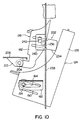
- the first opening-closing member 124' is mounted on the main body of the apparatus via a pair of linking members 268 (only one of them is shown).
- One linking member 268 is disposed on the side of one end of the first opening-closing member 124', and its one end is linked pivotally to one vertical base plate of the lower frame member via a pin 270.
- the other end of the linking member 268 is linked pivotally to one end wall 128' of the first opening-closing member 124'.
- the other linking member 268 is disposed on the side of the other end of the first opening-closing member 124', and its one end is pivotally linked to the other vertical base plate of the lower frame member via a pin while its other end is liked pivotally to the other end wall of the first opening-closing member 124' via a pin.
- first locking means 220' To open the first feed passage in the first modified example, one releases the first locking means 220' and then moves the first opening-closing member 124' from the operating position shown by a solid line toward the removed position in the direction shown by an arrow 274 and at the same time, pivots it from the closing position shown by a solid line toward the opening position shown by a two-dot chain line in the direction shown by an arrow 276.
- first opening-closing member 124' When the first opening-closing member 124' is pivoted to the opening position at the above removed position, its outside surface comes into contact with the upper surface of the table 260' as shown by a two-dot chain line in Figure 12 to maintain the first opening-closing member 124' at the opening position.
- the first opening-closing member 124' In mounting the first opening-closing member 124' as in the first modified example, too, the first opening-closing member 124' is moved toward the above-mentioned removed position at the time of opening the first feed passage and at the same time, pivoted toward the opening position. Accordingly, the first feed passage can be opened to a great extent as in the above-described embodiment.
- Figure 13 shows a second embodiment of the method of mounting the first opening-closing member.
- rail members 278 (one of which is shown) are provided in the inside surfaces of the pair of vertical base plates of the lower frame member.
- the rail member 278 is slightly inclined downwardly from one end (left side) to the other end (right side), and its other end portion extends downwardly in a nearly vertical direction.
- a pair of rollers 280 corresponding to one rail member 278 are rotatably mounted on the end wall 128'' of the first opening-closing member 124'', and although not shown, a pair of rollers 280 corresponding to the other rail member 278 are also rotatably mounted on the other end wall of the first opening-closing member 124''.
- the pair of rollers 280 are disposed vertically and positioned on both sides of the rail member 278 so as to hold them therebetween. Accordingly, the pair of rollers 280 can move along the rail member 278 while rotating. To prevent the pair of rollers 280 from being detached from the rail member 278, it is preferable to provide detachment preventing pieces 282 and 284 in both end portions of the rail member 278.
- the first opening-closing member 124'' is free to move between an operative position (shown by a solid line) at which the rollers 280 are positioned at one end portion of the rail member 278 and a removed position (shown by a two-dot chain line) at which the rollers 280 are positioned at the other end portion of the rail member 278 and at the same time free to pivot between the closing position shown by the solid line and the opening position shown by the two-dot chain line.
- the first opening-closing member 124'' At the time of opening the first feed passage, the first opening-closing member 124'', after the first locking means 220'' is released, is moved toward the removed position in the direction shown by an arrow 286 and pivoted toward the opening position in the direction shown by an arrow 288.
- the lower end portion of its outside comes into contact with the upper surface of the cable 260'' and is consequently held at the opening position.
- the first feed passage can be opened to a great extent.
Landscapes
- Physics & Mathematics (AREA)
- General Physics & Mathematics (AREA)
- Sheets, Magazines, And Separation Thereof (AREA)
- Feeding Of Articles By Means Other Than Belts Or Rollers (AREA)
- Paper Feeding For Electrophotography (AREA)
- Separation, Sorting, Adjustment, Or Bending Of Sheets To Be Conveyed (AREA)
- Conveyance By Endless Belt Conveyors (AREA)
- Delivering By Means Of Belts And Rollers (AREA)
Claims (12)
- Bilderzeugungsmaschine, die aufweist: einen Förderkanal (51), um ein Blattmaterial durch eine Übertragungszone (48) zu fördern, eine erste (66) und eine zweite (68) Zufuhreinrichtung, um das Blattmaterial dem Förderkanal (51) zuzuführen, einen ersten Zufuhrkanal (86), um das von der ersten Zufuhreinrichtung (66) abgegebene Blattmaterial zu dem Förderkanal (51) zu leiten, und einen zweiten Zufuhrkanal (96), um das von der zweiten Zufuhreinrichtung (68) abgegebene Blattmaterial zu dem Förderkanal (51) zu leiten,
dadurch gekennzeichnet, daß
mindestens ein größerer Bereich einer Seite des ersten Zufuhrkanals (86) von einem ersten Öffnungs/Schließelement (124) definiert ist und mindestens ein größerer Bereich seiner anderen Seite von einer Oberfläche eines zweiten Öffnungs/Schließelements (126) definiert ist,
mindestens ein größerer Bereich einer Seite des zweiten Zufuhrkanals (96) von der anderen Oberfläche des zweiten Öffnungs/Schließelements (126) definiert ist,
das erste Öffnung/Schließelement (124) frei ist, um zwischen einer Schließposition, in der es eine Seite des ersten Zufuhrkanals (86) definiert, und einer Öffnungsposition, in der es den ersten Zufuhrkanal (86) öffnet, zu schwenken, und
das zweite Öffnungs/Schließelement (126) frei ist, zwischen einer Schließposition, in der seine eine Oberfläche die andere Seite des ersten Zufuhrkanals (86) definiert und seine andere Oberfläche den zweiten Zufuhrkanal (96) definiert, und einer Öffnungsposition, in der es den zweiten Zufuhrkanal (96) öffnet, zu schwenken. - Bilderzeugungsvorrichtung nach Anspruch 1, wobei ein Paar von Stiften (154, 156) in einem von dem ersten Öffnungs/Schließelements (124) und dem Hauptkörper (2) der Maschine vorgesehen ist und schmale Aufnahmebereiche (164), die dem Paar von Stiften (154, 156) entsprechen, in dem anderen von dem ersten Öffnungs/Schließelement (124) und dem Hauptkörper (2) der Maschine vorgesehen sind und das Paar von Stiften (154, 156) ausgebildet ist, um jeweils in den entsprechenden Aufnahmebereichen (164) aufgenommen zu werden, so daß sie frei sind, um sich relativ zueinander entlang den Aufnahmebereichen (164) zwischen einer Betriebsposition in dem Hauptkörper (2) der Maschine und einer entfernten Position, die von der Betriebsposition entfernt ist, zu bewegen, und frei sind, um relativ zueinander zwischen der Schließposition und der Öffnungsposition zu schwenken.
- Bilderzeugungsmaschine nach Anspruch 1 oder 2, wobei das erste und das zweite Öffnungs/Schließelement (124, 126) derart ausgebildet sind, daß, wenn das zweite Öffnungs/Schließelement (126) nicht in der Schließposition ist, das erste Öffnungs/Schließelement (124) im wesentlichen nicht in der Schließposition gehalten werden kann.
- Bilderzeugungsmaschine nach einem der Ansprüche 1 bis 3, wobei eine erste Arretiereinrichtung (220) zum lösbaren Arretieren des ersten Öffnungs/Schließelements (124) in der Schließposition und eine zweite Arretiereinrichtung (232) zum lösbaren Arretieren des zweiten Öffnungs/Schließelements (126) in der Schließposition vorgesehen sind, und das erste und das zweite Öffnungs/Schließelement derart ausgebildet sind, daß, wenn das zweite Öffnungs/Schließelement (126) von der zweiten Arretiereinrichtung (232) nicht in der Schließposition arretiert ist, das erste Öffnungs/Schließelement (124) im wesentlichen nicht in der Schließposition gehalten werden kann.
- Bilderzeugungsmaschine nach Anspruch 4, wobei, wenn das zweite Öffnungs/Schließelement (126) von der zweiten Arretiereinrichtung (232) nicht in der Schließposition arretiert ist, das erste Öffnungs/Schließelement (124) in Richtung der Schließposition geschwenkt wird, das erste Öffnungs/Schließelement (124) mit einem Teil der zweiten Arretiereinrichtung (232) in Kontakt gelangt und im wesentlichen nicht in der Schließposition gehalten werden kann.
- Bilderzeugungsmaschine nach Anspruch 4 oder 5, wobei, wenn das zweite Öffnungs/Schließelement (126) von der zweiten Arretiereinrichtung (232) in der Schließposition arretiert ist und dann das erste Öffnungs/Schließelement (124) von der ersten Arretiereinrichtung (220) in der Schließposition arretiert wird, das erste Öffnungs/Schließelement (124) auf einen Teil der zweiten Arretiereinrichtung (232) einwirkt und die zweite Arretiereinrichtung (232) somit im wesentlichen nicht in dem Verriegelungsfreigabezustand gehalten werden kann.
- Bilderzeugungsmaschine nach Anspruch 6, wobei die zweite Arretiereinrichtung (232) einen Betätigungsbereich hat, der in dem zweiten Öffnungs/Schließelement (126) vorgesehen ist, so daß er zwischen einem arretierten Zustand und einem Verriegelungsfreigabezustand elastisch verformt werden kann; ein Eingriffsvorsprung (264, 268) in einem von dem Hauptkörper der Maschine, an dem das zweite Öffnungs/Schließelement (126) angebracht ist, und dem Betätigungsbereich der zweiten Arretiereinrichtung (232) vorgesehen ist und ein Aufnahmebereich zur lösbaren Aufnahme des Eingriffsvorsprungs in dem anderen von dem Hauptkörper und dem Betätigungsbereich definiert ist; wenn der Eingriffsvorsprung in der zweiten Arretiereinrichtung mit dem Aufnahmebereich in Eingriff ist, um das zweite Öffnungs/Schließelement (126) in der Schließposition zu arretieren, und dann das erste Öffnungs/Schließelement (124) von der ersten Arretiereinrichtung (220) in der Schließposition arretiert wird, das erste Öffnungs/Schließelement (124) auf den Betätigungsbereich einwirkt und der Betätigungsbereich somit im wesentlichen nicht in dem Verriegelungsfreigabezustand gehalten werden kann.
- Bilderzeugungsmaschine nach Anspruch 2, wobei eine Vorspannfeder (244) angeordnet ist, um das erste Öffnungs/Schließelement (124) in Richtung der Öffnungsposition vorzuspannen, und die Vorspannfeder (244) als eine abstützende Führung wirkt, wenn das erste Öffnungs/Schließelement (124) zwischen der Betriebsposition und der entfernten Position bewegt wird.
- Bilderzeugungsmaschine nach Anspruch 8, wobei aufgrund der Vorspannung des Öffnungs/Schließelements (124) durch die Vorspannwirkung der Vorspanneinrichtung (244) in Richtung der Öffnungsposition die erste Arretiereinrichtung (220) das erste Öffnungs/Schließelement (124) in der Schließposition arretiert; und das durch den Kanal (86) geförderte Blattmaterial wirksam ist, um das erste Öffnungs/Schließelement (124) in Richtung der Öffnungsposition zu schwenken.
- Bilderzeugungsmaschine nach einem der Ansprüche 1 bis 9, wobei die erste Zufuhreinrichtung (66) und die zweite Zufuhreinrichtung (68) jeweils aufweisen: einen Kassettenaufnahmeabschnitt (78, 88), der in dem Hauptkörper (2) der Maschine definiert ist, eine Kassette (82, 92), in der Blattmaterial angeordnet ist und die ausgebildet ist, um abnehmbar in den Kassettenaufnahmeabschnitt (78, 88) geladen zu werden, und eine Förderwalze (84, 94), die über dem Kassettenaufnahmeabschnitt angeordnet ist, und wobei die Innenfläche von mindestens einem von dem ersten (124) und dem zweiten (126) Öffnungs/Schließelement sich bogenförmig von dem Kassettenaufnahmeabschnitt (78, 88) nach oben in Richtung des Förderkanal (51) erstreckt, und vertiefte Kontaktverhinderungsbereiche (146, 196), um beide Endbereiche des Vorderendes des aus der Kassette (82, 92) abgegebenen Blattmaterials daran zu hindern, mit dem Öffnungs/Schließelement in Kontakt zu gelangen, an beiden Endbereichen in der Breitenrichtung der aufstromseitigen Endbereiche der sich nach oben erstreckenden Innenfläche vorgesehen sind.
- Bilderzeugungsmaschine nach Anspruch 10, wobei ein Einführvorsprung (148, 188), der geringfügig in den Kassettenaufnahmeabschnitt (78, 88) vorspringt, an einem mittleren Teil in der Breitenrichtung des aufstromseitigen Endes der Innenfläche von einem von dem ersten (124) und dem zweiten (126) Öffnungs/Schließelement vorgesehen ist.
- Bilderzeugungsmaschine nach einem der Ansprüche 1 bis 11, wobei das erste Öffnungs/Schließelement (124) an dem Hauptkörper (2) der Maschine abnehmbar angebracht ist.
Priority Applications (2)
| Application Number | Priority Date | Filing Date | Title |
|---|---|---|---|
| EP93114094A EP0574043B1 (de) | 1988-09-27 | 1989-09-27 | Bilderzeugungsgerät |
| EP93114093A EP0574042B1 (de) | 1988-09-27 | 1989-09-27 | Bilderzeugungsgerät |
Applications Claiming Priority (2)
| Application Number | Priority Date | Filing Date | Title |
|---|---|---|---|
| JP239830/88 | 1988-09-27 | ||
| JP63239830A JPH0734142B2 (ja) | 1988-09-27 | 1988-09-27 | 画像形成装置 |
Related Child Applications (5)
| Application Number | Title | Priority Date | Filing Date |
|---|---|---|---|
| EP93114093A Division EP0574042B1 (de) | 1988-09-27 | 1989-09-27 | Bilderzeugungsgerät |
| EP93114093.3 Division-Into | 1993-09-02 | ||
| EP93114095.8 Division-Into | 1993-09-02 | ||
| EP93114094.1 Division-Into | 1993-09-02 | ||
| EP93114096.6 Division-Into | 1993-09-02 |
Publications (3)
| Publication Number | Publication Date |
|---|---|
| EP0361426A2 EP0361426A2 (de) | 1990-04-04 |
| EP0361426A3 EP0361426A3 (de) | 1991-11-27 |
| EP0361426B1 true EP0361426B1 (de) | 1994-05-11 |
Family
ID=17050488
Family Applications (5)
| Application Number | Title | Priority Date | Filing Date |
|---|---|---|---|
| EP93114094A Expired - Lifetime EP0574043B1 (de) | 1988-09-27 | 1989-09-27 | Bilderzeugungsgerät |
| EP89117823A Expired - Lifetime EP0361426B1 (de) | 1988-09-27 | 1989-09-27 | Bildaufzeichnungsgerät |
| EP93114093A Expired - Lifetime EP0574042B1 (de) | 1988-09-27 | 1989-09-27 | Bilderzeugungsgerät |
| EP19930114095 Withdrawn EP0574044A1 (de) | 1988-09-27 | 1989-09-27 | Bilderzeugungsgerät |
| EP19930114096 Withdrawn EP0574045A1 (de) | 1988-09-27 | 1989-09-27 | Bilderzeugungsgerät |
Family Applications Before (1)
| Application Number | Title | Priority Date | Filing Date |
|---|---|---|---|
| EP93114094A Expired - Lifetime EP0574043B1 (de) | 1988-09-27 | 1989-09-27 | Bilderzeugungsgerät |
Family Applications After (3)
| Application Number | Title | Priority Date | Filing Date |
|---|---|---|---|
| EP93114093A Expired - Lifetime EP0574042B1 (de) | 1988-09-27 | 1989-09-27 | Bilderzeugungsgerät |
| EP19930114095 Withdrawn EP0574044A1 (de) | 1988-09-27 | 1989-09-27 | Bilderzeugungsgerät |
| EP19930114096 Withdrawn EP0574045A1 (de) | 1988-09-27 | 1989-09-27 | Bilderzeugungsgerät |
Country Status (4)
| Country | Link |
|---|---|
| US (2) | US5052670A (de) |
| EP (5) | EP0574043B1 (de) |
| JP (1) | JPH0734142B2 (de) |
| DE (3) | DE68926539T2 (de) |
Families Citing this family (59)
| Publication number | Priority date | Publication date | Assignee | Title |
|---|---|---|---|---|
| JP2593227B2 (ja) * | 1989-12-11 | 1997-03-26 | キヤノン株式会社 | 給紙装置 |
| JP2512561Y2 (ja) * | 1990-04-03 | 1996-10-02 | カシオ電子工業株式会社 | 画像形成装置 |
| US5238235A (en) * | 1990-08-10 | 1993-08-24 | Canon Kabushiki Kaisha | Sheet feeding apparatus |
| JPH04182260A (ja) * | 1990-11-17 | 1992-06-29 | Mita Ind Co Ltd | 排紙トレイ |
| KR940003112B1 (ko) * | 1991-10-25 | 1994-04-13 | 삼성전자 주식회사 | 전자사진방식을 이용한 기기에 사용되는 카세트 |
| DE4239621C2 (de) * | 1991-11-26 | 1995-02-09 | Mutoh Ind Ltd | Flachbettscanner mit einem Papierleitelement |
| US5303017A (en) * | 1993-05-07 | 1994-04-12 | Xerox Corporation | Print skip avoidance for on-line compiling |
| JP3093560B2 (ja) * | 1993-05-10 | 2000-10-03 | キヤノン株式会社 | 画像形成装置 |
| KR0115024Y1 (ko) * | 1993-06-21 | 1998-04-16 | 구자홍 | 레이져빔 프린터의 급배지장치 |
| JP3110662B2 (ja) * | 1994-11-07 | 2000-11-20 | キヤノン株式会社 | シート供給装置および画像形成装置 |
| JP3124205B2 (ja) * | 1995-02-24 | 2001-01-15 | キヤノン株式会社 | 再給送装置及び画像形成装置 |
| US5785308A (en) * | 1995-11-28 | 1998-07-28 | Lexmark International, Inc. | Media pass through configuration for printers |
| US5711517A (en) * | 1996-03-07 | 1998-01-27 | Hewlett-Packard Company | Sheet media handling system |
| JPH10129860A (ja) * | 1996-10-31 | 1998-05-19 | Canon Inc | 記録装置 |
| EP0872351B1 (de) * | 1997-04-09 | 2004-06-30 | Seiko Epson Corporation | Dokumentenzuführvorrichtung für einen Drucker |
| JP3351986B2 (ja) | 1997-05-21 | 2002-12-03 | シャープ株式会社 | シート給送装置 |
| US5913095A (en) * | 1997-08-25 | 1999-06-15 | Ricoh Company, Ltd. | Image forming apparatus |
| JP2001122447A (ja) * | 1999-10-20 | 2001-05-08 | Canon Inc | シート給送装置及び画像形成装置 |
| US6511241B2 (en) * | 2001-01-12 | 2003-01-28 | Hewlett-Packard Company | Integral actuation linkage for paper diverter for switch to straight-through paper path |
| JP3546024B2 (ja) * | 2001-03-27 | 2004-07-21 | 京セラミタ株式会社 | 用紙搬送装置 |
| KR20050046425A (ko) * | 2003-11-14 | 2005-05-18 | 삼성전자주식회사 | 복합기 |
| US7448621B2 (en) * | 2004-03-29 | 2008-11-11 | Canon Kabushiki Kaisha | Sheet conveying apparatus and image forming apparatus |
| KR100608078B1 (ko) * | 2004-07-16 | 2006-08-08 | 엘지엔시스(주) | 매체자동지급기 |
| JP2006103954A (ja) * | 2004-10-08 | 2006-04-20 | Brother Ind Ltd | 画像記録装置 |
| JP4207962B2 (ja) * | 2006-01-24 | 2009-01-14 | ブラザー工業株式会社 | 給紙装置 |
| JP4207963B2 (ja) * | 2006-01-24 | 2009-01-14 | ブラザー工業株式会社 | 給紙装置 |
| US7561823B2 (en) * | 2006-04-06 | 2009-07-14 | Lexmark International, Inc. | Short passive duplex unit and method of use |
| JP4508244B2 (ja) * | 2008-01-31 | 2010-07-21 | ブラザー工業株式会社 | シート搬送装置、及びこれを備えた画像記録装置 |
| JP4766282B2 (ja) * | 2008-09-30 | 2011-09-07 | ブラザー工業株式会社 | 画像記録装置 |
| JP4697324B2 (ja) * | 2009-03-27 | 2011-06-08 | ブラザー工業株式会社 | 現像剤カートリッジ、画像形成装置および現像装置 |
| JP5023140B2 (ja) * | 2009-12-11 | 2012-09-12 | シャープ株式会社 | 搬送装置 |
| JP5545058B2 (ja) * | 2010-06-17 | 2014-07-09 | ブラザー工業株式会社 | 画像記録装置 |
| ES3008182T3 (en) | 2011-11-10 | 2025-03-21 | Packsize Llc | Converting machine |
| US10052838B2 (en) * | 2012-01-09 | 2018-08-21 | Packsize Llc | Converting machine with an upward outfeed guide |
| JP5955711B2 (ja) * | 2012-09-11 | 2016-07-20 | シチズンホールディングス株式会社 | プリンタ |
| JP2014182273A (ja) * | 2013-03-19 | 2014-09-29 | Fuji Xerox Co Ltd | 画像形成システムおよび用紙処理装置 |
| JP6035267B2 (ja) * | 2014-02-27 | 2016-11-30 | 京セラドキュメントソリューションズ株式会社 | 画像形成装置 |
| JP6075318B2 (ja) | 2014-03-28 | 2017-02-08 | ブラザー工業株式会社 | 画像形成装置 |
| JP6128035B2 (ja) * | 2014-03-28 | 2017-05-17 | ブラザー工業株式会社 | 画像形成装置 |
| JP6468819B2 (ja) * | 2014-11-28 | 2019-02-13 | キヤノン株式会社 | 画像形成装置 |
| US10093438B2 (en) | 2014-12-29 | 2018-10-09 | Packsize Llc | Converting machine |
| JP6463239B2 (ja) * | 2015-09-08 | 2019-01-30 | キヤノン株式会社 | シート搬送装置及び画像形成装置。 |
| US9851676B2 (en) * | 2015-10-23 | 2017-12-26 | Brother Kogyo Kabushiki Kaisha | Conveying apparatus, sheet conveying apparatus and image recording apparatus |
| JP6686476B2 (ja) | 2016-01-29 | 2020-04-22 | ブラザー工業株式会社 | シート搬送装置及び画像記録装置 |
| US10850469B2 (en) | 2016-06-16 | 2020-12-01 | Packsize Llc | Box forming machine |
| ES2848561T3 (es) | 2016-06-16 | 2021-08-10 | Packsize Llc | Un procedimiento y sistema de producción de plantillas de caja |
| US11242214B2 (en) | 2017-01-18 | 2022-02-08 | Packsize Llc | Converting machine with fold sensing mechanism |
| SE541921C2 (en) | 2017-03-06 | 2020-01-07 | Packsize Llc | A box erecting method and system |
| SE540672C2 (en) | 2017-06-08 | 2018-10-09 | Packsize Llc | Tool head positioning mechanism for a converting machine, and method for positioning a plurality of tool heads in a converting machine |
| US10511735B2 (en) * | 2017-07-13 | 2019-12-17 | Konica Minolta, Inc. | Image forming apparatus |
| US11173685B2 (en) | 2017-12-18 | 2021-11-16 | Packsize Llc | Method for erecting boxes |
| US11247427B2 (en) | 2018-04-05 | 2022-02-15 | Avercon BVBA | Packaging machine infeed, separation, and creasing mechanisms |
| US11305903B2 (en) | 2018-04-05 | 2022-04-19 | Avercon BVBA | Box template folding process and mechanisms |
| WO2019246344A1 (en) | 2018-06-21 | 2019-12-26 | Packsize Llc | Packaging machine and systems |
| SE543046C2 (en) | 2018-09-05 | 2020-09-29 | Packsize Llc | A box erecting method and system |
| US11524474B2 (en) | 2018-11-30 | 2022-12-13 | Packsize Llc | Adjustable cutting and creasing heads for creating angled cuts and creases |
| DE112020000348T5 (de) | 2019-01-07 | 2021-09-16 | Packsize Llc | Kartonaufrichtungsmaschine |
| US11701854B2 (en) | 2019-03-14 | 2023-07-18 | Packsize Llc | Packaging machine and systems |
| JP2025017498A (ja) * | 2023-07-25 | 2025-02-06 | セイコーエプソン株式会社 | 記録装置 |
Family Cites Families (23)
| Publication number | Priority date | Publication date | Assignee | Title |
|---|---|---|---|---|
| US3476382A (en) * | 1965-09-09 | 1969-11-04 | Addressograph Multigraph | Photoelectrostatic copying machine |
| JPS5347008B1 (de) * | 1970-03-13 | 1978-12-18 | ||
| DE2521932A1 (de) * | 1975-05-16 | 1976-11-25 | Agfa Gevaert Ag | Kopiergeraet |
| US4492371A (en) * | 1980-02-22 | 1985-01-08 | Canon Kabushiki Kaisha | Feeding device |
| US4456362A (en) * | 1981-02-05 | 1984-06-26 | Canon Kabushiki Kaisha | Portable image forming apparatus |
| JPS5821270A (ja) * | 1981-07-30 | 1983-02-08 | Minolta Camera Co Ltd | 記録装置 |
| JPS58125065A (ja) * | 1982-01-20 | 1983-07-25 | Konishiroku Photo Ind Co Ltd | 可変倍複写装置 |
| JPS5940664A (ja) * | 1982-08-31 | 1984-03-06 | Fuji Xerox Co Ltd | 複写機用コピ−用紙送り装置 |
| JPH0623872B2 (ja) * | 1982-11-30 | 1994-03-30 | 三田工業株式会社 | 静電複写機 |
| US4607942A (en) * | 1983-09-19 | 1986-08-26 | Mita Industrial Co., Ltd. | Electrostatic copying apparatus |
| US4583844A (en) * | 1983-09-19 | 1986-04-22 | Konishiroku Photo Industry Co., Ltd. | Image recording apparatus with separable upper and lower sections and displaceable paper feed unit |
| JPS6067968A (ja) * | 1983-09-24 | 1985-04-18 | Casio Comput Co Ltd | 給紙装置 |
| US4609281A (en) * | 1984-02-08 | 1986-09-02 | Sanyo Electric Co., Ltd. | Portable electrostatographic copying machine |
| JPS61128264A (ja) * | 1984-11-27 | 1986-06-16 | Sanyo Electric Co Ltd | 静電記録装置 |
| US4866487A (en) * | 1985-04-05 | 1989-09-12 | Canon Kabushiki Kaisha | Image forming apparatus |
| DE3674066D1 (de) * | 1985-05-24 | 1990-10-18 | Mita Industrial Co Ltd | Papierzufuehrungsvorrichtung. |
| JPS6286369U (de) * | 1985-11-19 | 1987-06-02 | ||
| US4766467A (en) * | 1985-11-28 | 1988-08-23 | Mita Industrial Co. Ltd. | Electrostatic copying apparatus and auxiliary unit capable of being detachably mounted thereon |
| DE3607080A1 (de) * | 1986-03-04 | 1987-09-10 | Mannesmann Ag | Vorrichtung fuer den papiertransport in druckern mit balkenfoermigem druckwiderlager, insbesondere in matrixdruckern |
| EP0237050B1 (de) * | 1986-03-14 | 1990-06-13 | Sharp Kabushiki Kaisha | Kassette für Kopien |
| US4733310A (en) * | 1986-05-23 | 1988-03-22 | Ziyad, Inc. | Paper sheet and envelope feeder apparatus |
| GB2197258B (en) * | 1986-09-05 | 1991-05-22 | Ricoh Kk | Electrostatic recording apparatus |
| JPS63218437A (ja) * | 1987-03-03 | 1988-09-12 | Seikosha Co Ltd | プリンタ用給紙装置 |
-
1988
- 1988-09-27 JP JP63239830A patent/JPH0734142B2/ja not_active Expired - Lifetime
-
1989
- 1989-09-18 US US07/408,275 patent/US5052670A/en not_active Expired - Lifetime
- 1989-09-27 DE DE68926539T patent/DE68926539T2/de not_active Expired - Lifetime
- 1989-09-27 EP EP93114094A patent/EP0574043B1/de not_active Expired - Lifetime
- 1989-09-27 EP EP89117823A patent/EP0361426B1/de not_active Expired - Lifetime
- 1989-09-27 DE DE68927190T patent/DE68927190T2/de not_active Expired - Lifetime
- 1989-09-27 EP EP93114093A patent/EP0574042B1/de not_active Expired - Lifetime
- 1989-09-27 EP EP19930114095 patent/EP0574044A1/de not_active Withdrawn
- 1989-09-27 DE DE68915235T patent/DE68915235T2/de not_active Expired - Fee Related
- 1989-09-27 EP EP19930114096 patent/EP0574045A1/de not_active Withdrawn
-
1991
- 1991-02-27 US US07/661,300 patent/US5118093A/en not_active Expired - Lifetime
Also Published As
| Publication number | Publication date |
|---|---|
| EP0361426A2 (de) | 1990-04-04 |
| EP0574042A1 (de) | 1993-12-15 |
| US5052670A (en) | 1991-10-01 |
| JPH0734142B2 (ja) | 1995-04-12 |
| DE68926539T2 (de) | 1997-01-23 |
| EP0574042B1 (de) | 1996-09-11 |
| EP0574045A1 (de) | 1993-12-15 |
| DE68915235D1 (de) | 1994-06-16 |
| DE68927190D1 (de) | 1996-10-17 |
| DE68927190T2 (de) | 1997-03-27 |
| DE68926539D1 (de) | 1996-06-27 |
| EP0574043A1 (de) | 1993-12-15 |
| DE68915235T2 (de) | 1995-01-05 |
| EP0574043B1 (de) | 1996-05-22 |
| US5118093A (en) | 1992-06-02 |
| EP0574044A1 (de) | 1993-12-15 |
| JPH0290177A (ja) | 1990-03-29 |
| EP0361426A3 (de) | 1991-11-27 |
Similar Documents
| Publication | Publication Date | Title |
|---|---|---|
| EP0574042B1 (de) | Bilderzeugungsgerät | |
| US4862212A (en) | Image forming apparatus | |
| EP0526916A2 (de) | Bilderzeugungsgerät | |
| US5918875A (en) | Zero clearance handle | |
| US20090092413A1 (en) | Photosensitive member cartridge | |
| US5284333A (en) | Sheet feeding apparatus | |
| US20250291306A1 (en) | Image forming apparatus | |
| US4915370A (en) | Paper feeding device | |
| JP3705351B2 (ja) | 画像形成装置 | |
| US20250291309A1 (en) | Image forming apparatus | |
| JPWO2000005627A1 (ja) | 画像形成装置 | |
| JP2001187642A (ja) | 給紙カセット | |
| EP0485786B1 (de) | Blattzuführgerät | |
| JP2025056945A (ja) | 画像形成装置 | |
| JP3658138B2 (ja) | シート積載装置および画像形成装置 | |
| JP2512699Y2 (ja) | 画像形成装置 | |
| US11754968B2 (en) | Image forming apparatus | |
| JPH0822705B2 (ja) | 画像生成装置 | |
| JPH05297666A (ja) | 電子写真装置 | |
| JP3633391B2 (ja) | シート供給装置および画像形成装置 | |
| EP0448023B1 (de) | Aufbau der Tragwelle für Rollenpapier | |
| JP2001253567A (ja) | 画像形成機の給紙装置 | |
| JP2632326B2 (ja) | 画像形成装置 | |
| JPH04314061A (ja) | 画像形成装置 | |
| JP2018188269A (ja) | 給紙カセット及びこれを備えた画像形成装置 |
Legal Events
| Date | Code | Title | Description |
|---|---|---|---|
| PUAI | Public reference made under article 153(3) epc to a published international application that has entered the european phase |
Free format text: ORIGINAL CODE: 0009012 |
|
| AK | Designated contracting states |
Kind code of ref document: A2 Designated state(s): DE FR GB IT NL |
|
| 17P | Request for examination filed |
Effective date: 19901221 |
|
| PUAL | Search report despatched |
Free format text: ORIGINAL CODE: 0009013 |
|
| AK | Designated contracting states |
Kind code of ref document: A3 Designated state(s): DE FR GB IT NL |
|
| 17Q | First examination report despatched |
Effective date: 19921218 |
|
| GRAA | (expected) grant |
Free format text: ORIGINAL CODE: 0009210 |
|
| AK | Designated contracting states |
Kind code of ref document: B1 Designated state(s): DE FR GB IT NL |
|
| ITF | It: translation for a ep patent filed | ||
| REF | Corresponds to: |
Ref document number: 68915235 Country of ref document: DE Date of ref document: 19940616 |
|
| ET | Fr: translation filed | ||
| PLBE | No opposition filed within time limit |
Free format text: ORIGINAL CODE: 0009261 |
|
| STAA | Information on the status of an ep patent application or granted ep patent |
Free format text: STATUS: NO OPPOSITION FILED WITHIN TIME LIMIT |
|
| 26N | No opposition filed | ||
| PGFP | Annual fee paid to national office [announced via postgrant information from national office to epo] |
Ref country code: NL Payment date: 19970929 Year of fee payment: 9 |
|
| PGFP | Annual fee paid to national office [announced via postgrant information from national office to epo] |
Ref country code: DE Payment date: 19971010 Year of fee payment: 9 |
|
| PGFP | Annual fee paid to national office [announced via postgrant information from national office to epo] |
Ref country code: FR Payment date: 19980909 Year of fee payment: 10 |
|
| PG25 | Lapsed in a contracting state [announced via postgrant information from national office to epo] |
Ref country code: NL Free format text: LAPSE BECAUSE OF NON-PAYMENT OF DUE FEES Effective date: 19990401 |
|
| NLV4 | Nl: lapsed or anulled due to non-payment of the annual fee |
Effective date: 19990401 |
|
| PG25 | Lapsed in a contracting state [announced via postgrant information from national office to epo] |
Ref country code: DE Free format text: LAPSE BECAUSE OF NON-PAYMENT OF DUE FEES Effective date: 19990701 |
|
| PG25 | Lapsed in a contracting state [announced via postgrant information from national office to epo] |
Ref country code: FR Free format text: LAPSE BECAUSE OF NON-PAYMENT OF DUE FEES Effective date: 20000531 |
|
| REG | Reference to a national code |
Ref country code: FR Ref legal event code: ST |
|
| REG | Reference to a national code |
Ref country code: GB Ref legal event code: IF02 |
|
| PG25 | Lapsed in a contracting state [announced via postgrant information from national office to epo] |
Ref country code: IT Free format text: LAPSE BECAUSE OF NON-PAYMENT OF DUE FEES Effective date: 20050927 |
|
| PGFP | Annual fee paid to national office [announced via postgrant information from national office to epo] |
Ref country code: GB Payment date: 20081001 Year of fee payment: 20 |
|
| REG | Reference to a national code |
Ref country code: GB Ref legal event code: PE20 Expiry date: 20090926 |
|
| PG25 | Lapsed in a contracting state [announced via postgrant information from national office to epo] |
Ref country code: GB Free format text: LAPSE BECAUSE OF EXPIRATION OF PROTECTION Effective date: 20090926 |