EP0361432B1 - Verfahren und Einrichtung zur Codierung und Decodierung von Sprachsignalen unter Anwendung von Multipuls-Anregung - Google Patents
Verfahren und Einrichtung zur Codierung und Decodierung von Sprachsignalen unter Anwendung von Multipuls-Anregung Download PDFInfo
- Publication number
- EP0361432B1 EP0361432B1 EP89117837A EP89117837A EP0361432B1 EP 0361432 B1 EP0361432 B1 EP 0361432B1 EP 89117837 A EP89117837 A EP 89117837A EP 89117837 A EP89117837 A EP 89117837A EP 0361432 B1 EP0361432 B1 EP 0361432B1
- Authority
- EP
- European Patent Office
- Prior art keywords
- signal
- long
- term
- gain
- excitation
- Prior art date
- Legal status (The legal status is an assumption and is not a legal conclusion. Google has not performed a legal analysis and makes no representation as to the accuracy of the status listed.)
- Expired - Lifetime
Links
Images


Classifications
-
- G—PHYSICS
- G10—MUSICAL INSTRUMENTS; ACOUSTICS
- G10L—SPEECH ANALYSIS TECHNIQUES OR SPEECH SYNTHESIS; SPEECH RECOGNITION; SPEECH OR VOICE PROCESSING TECHNIQUES; SPEECH OR AUDIO CODING OR DECODING
- G10L19/00—Speech or audio signals analysis-synthesis techniques for redundancy reduction, e.g. in vocoders; Coding or decoding of speech or audio signals, using source filter models or psychoacoustic analysis
- G10L19/04—Speech or audio signals analysis-synthesis techniques for redundancy reduction, e.g. in vocoders; Coding or decoding of speech or audio signals, using source filter models or psychoacoustic analysis using predictive techniques
- G10L19/08—Determination or coding of the excitation function; Determination or coding of the long-term prediction parameters
- G10L19/10—Determination or coding of the excitation function; Determination or coding of the long-term prediction parameters the excitation function being a multipulse excitation
Definitions
- the present invention concerns medium-low bit-race speech signal coding systems, and more particularly it relates to a coding-decoding method and device using a multipulse analysis-by-synthesis excitation technique.
- Multipulse linear prediction coding is one of the most promising techniques for obtaining high quality synthetic speech at bit rates below 16 kbit/s. This technique has been originally proposed by B. S. Atal and J. R. Remde in the paper entitled “A new method of LPC excitation for producing natural-sounding speech at low bit rates", International Conference on Acoustic, Speech, Signal Processing (ICASSP), pages 614-617, Paris, 1982.
- IICASSP International Conference on Acoustic, Speech, Signal Processing
- the excitation signal for the synthesis filter consists of a train of pulses whose amplitudes and time positions are determined so as to minimize a perceptually-meaningful distorsion measurement; such a measurement is obtained by comparing the samples at the synthesis filter output with the original speech samples and simultaneous weighting the difference by a function which takes into account how the human perception evaluates the distorsion introduced (analysis-by-synthesis procedure).
- the synthesizer comprises the cascade of a long-term and a short-term synthesis filter are of particular interest: in fact they provide signals whose quality gradually decreases as the bit rate decreases and do not present a dramatic performance deterioration below a threshold rate.
- the invention provides a method and a device allowing quality to be increased leaving the bit rate unchanged or a given quality to be maintained even at lower bit rate.
- This can be achieved by using a combined optimization technique, of sequential type, of the parameters of the long-term synthesis filter and of the excitation within the analysis-by-synthesis procedure; the sequential procedure is sub-optimum with respect to the original optimum one, but it is easier to be implemented.
- a method is provided where an optimization of parameters according to the particular error minimization procedure is used, which is a closed loop analysis.
- the terms "open loop analysis” and “closed loop analysis” are here used as explained e.g. in IEEE Journal on Selected Areas in communications, Vol. 6 No. 2, Feb. 1988, p.353-363, Kroon and Deprettere.
- the long-term analysis means are apt to determine said lag and gain in two successive steps, preceding a step in which the amplitudes and positions of the excitation pulses are determined by said excitation generator, and comprise: a second long-term synthesis filter, which is fed with a null signal and in which, for the computation of the lag, there is used
- a generic speech signal coding-decoding system can be schematized by a coder COD, a transmission channel CH and a decoder DEC.
- coder COD receives digital samples s(n) of the original speech signal, organized into frames comprising each a predetermined number of samples, and sends onto channel CH, for each sample frame, the coding of a suitable representation ⁇ (k) of a group of linear prediction coefficients a(k) obtained by a short-term analysis of the speech signal, the coded amplitudes and positions A(i), Cp of the pulses forming the excitation signal, the coded r.m.s. values ⁇ (i) of the excitation pulses, and the codings of two parameters (gain B and lag M) determined by the long-term analysis.
- Decoder DEC reconstructs the excitation and generates a synthesized speech signal on the basis of the reconstructed excitation, the linear prediction coefficients reconstructed starting from the transmitted representation thereof, and long-term analysis parameters.
- the digital sample frames, present on connection 1 are supplied to a spectral shaping circuit SW and to a short-term analysis circuit STA.
- Spectral shaping circuit SW performs a frequency-shaping of the speech signal in order to render the differences between the original and the reconstructed speech signals less perceptible in correspondence with the formants of the original speech signal.
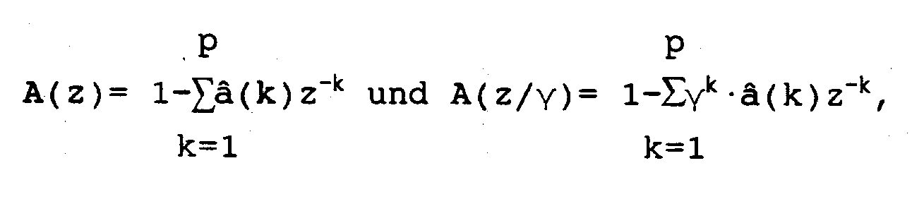
- Such a circuit consists of a pair of cascaded digital filters F1, F2, whose transfer functions, in z transform, are given in a non-limiting example respectively by relations where z represents a sampling interval delay; â(k) is a quantized linear prediction coefficient vector (1 ⁇ k ⁇ p, where p is the filter order) reconstructed from the coded representation of the linear prediction coefficients obtained as short-term analysis result; ⁇ is an experimentally determined constant correcting factor, determining the bandwidth increase around the formants.
- a signal r(n) hereinafter referred to as “residual signal”
- spectrally shaped speech signal s w (n) is obtained on output connection 3 of F2: both signals are used in long-term analysis.
- Short-term analysis circuit STA is to determine linear prediction coefficients a(k), which depend on short-term correlations deriving from a non-flat spectral envelope of speech signal. Circuit STA calculates coefficients a(k) according to the classical autocorrelation method, as described in "Digital Signal Processing of Speech Signals" by L.R. Rabiner and R.W. Schafer (Prentice-Hall, Englewood Cliffs, N.J., USA, 1978), page 401, and uses to this aim a set of digital samples s h (n) which can comprise, besides the samples of the current frame, a certain number of samples of both the preceding and the following frames.
- Block STA also comprises circuits for transforming the coefficients into a group of parameters ⁇ (k) in the frequency domain, known as "line spectrum pairs", which are presented on output 5 of STA.
- line spectrum pairs denote the resonant frequencies at which the acoustic tube, the vocal tract can be assimilated to, exhibits a line spectrum structure under extreme boundary conditions corresponding to complete opening and closure at the glottis.
- the conversion of linear prediction coefficients into line spectrum pairs is described e.g. by N. Sugamura and F.Itakura in the paper "Speech analysis and synthesis method developed at ECL in NTT - From LPC to LSP", Speech Communication, Vol.5, No.2, June 1986, pages 199-215.
- Line spectrum pairs ⁇ (k) or the differences ⁇ between adjacent line pairs are then vectorially quantized in a vector quantization circuit VQ exploiting techniques of the type described in published European Patent application EP-A-186763 (CSELT), applied to a set of codebooks.
- CSELT published European Patent application EP-A-186763
- That vector instead of being coded by a single word with that number of bits, is quantized by a group of words of smaller size chosen out of suitable sub-codebooks.
- the modality of quantization of the above patent application are applied to obtain each of said words.
- vector quantizer VQ is one of the characteristics of the present invention and allows a reduction in the number of bits necessary to code the results of the short-term analysis, while maintaining the same quality of the coded signal, from about 36-34 bits (scalar quantization) to 24 (vector quantization).
- differences ⁇ organized into three vectors of 3, 3 and 4 components respectively, may be quantized with 24 bits organized into three groups of 256 words, each group corresponding to one of said vectors.
- the indices of the vectors are sent by VQ on a connection 6 which belongs to channel CH.
- a circuit DCO obtains from said indices quantized linear prediction coefficients â(k) which are supplied, through connection 4, to filters F1, F2 or circuit SW, to an excitation generator EG and to a long-term analysis circuit LTA.
- LTA supplies information dependent on the fine spectral structure of the signal, which information is used to make the synthesized signal more natural-sounding.
- the samples relevant to M preceding sampling instants weighted by a weighting factor (gain) 3, are used.
- LTA is just to determine both M and B.
- Lag M in case of a voiced sound, corresponds to the pitch period.
- the lag can range from 20 to 83 samples and it is updated every frame. The gain is on the contrary updated every half frame.
- Values M and B are emitted on a connection 7 and are supplied to excitation generator EG which also receives, through a connection 8, a signal s we (n), obtained from s w (n) in a manner which will be described hereinafter. Values M and B are also sent to a coder LTC, which transfers the coded signals onto a connection 9 belonging to channel CH.
- LTC liquid crystal display
- Long-term analysts circuit LTA performs a closed-loop analysis as a part of the procedure for determining the pulse positions, with modalities allowing a good coder performance to be maintained even if a sub-optimum procedure is used, as will be better described hereinafter.
- Excitation generator EG is to supply the sequence of Ns pulses (e.g. 6), distributed within a time period Ls (more particularly corresponding to half a frame), forming the excitation signal; such a signal is computed so as to minimize a mean squared error, frequency shaped as mentioned, between the original signal and the reconstructed one.
- Ns pulses e.g. 6
- Ls more particularly corresponding to half a frame
- Excitation generator EG supplies, through a connection 10, the pulses it has generated to a circuit PAC coding the amplitudes and the positions of such pulses, which circuits calculate and code also the r.m.s. values of said pulses.
- the coded values ⁇ (i), A(i) (1 ⁇ i ⁇ Ns) and Cp are emitted on a connection 11, also belonging to channel CH.
- circuit PAC The structure of circuit PAC is known to the skilled in the art.
- an excitation decoder ED reconstructs the excitation starting from the coded values ⁇ (i), A(i), Cp.
- reconstructed excitation pulses ê are supplied by ED to a long-term synthesis filter LTP1 which, together with a short-term synthesis filter STP, forms synthesizer SYN.
- Reconstructed residual signal r ⁇ is present at the output of LTP1 and is sent via a connection 14 to short-term synthesis filter STP.
- This is a filter whose transfer function in z transform is 1/A(z), where A(z) is the function already examined for filter F1 of spectral shaping circuit SW.
- Coefficients â(k) for filter STP are supplied through a connection 15 from a circuit STD, which reconstructs them by decoding the information relevant to line spectrum pairs.
- Filter STP emits on connection 16 the reconstructed or synthesized speech signal ⁇ .
- the optimum solution would be determining, for each pair of possible values m, b of the lag and gain used to determine the optimum values M, B to be exploited in the synthesis, the combination of excitation pulses, gain and lag minimizing the mean squared error between the original signal and the reconstructed signal.
- the optimum solution is too complex and hence, according to the invention, the determination of M and B is separated from that of the excitation pulses There are hence two successive operation phases.
- M, B of m and b are to be found which minimize mean squared error between frequency-shaped speech signal s w (n) and a signal s w0 (n) obtained by weighting, in the same way as the residual signal, a signal r0 obtained as a response from a long-term synthesis filter (similar to the one of the synthesizer), when at the filter input a zero has been forced (long-term synthesis filter memory).
- a predetermined value b is allotted to the gain and the error is minimized for each value m of lag: once found optimum lag M, the successive step is that of determining the optimum gain B.
- value B of b is chosen which renders E(M, b) minimum.
- B is computed every half frame, and hence also the excitation pulses will be computed every half frame.
- Fig. 3 shows a block diagram of the devices of LTP and EG in case signal 0 is used to determine M and B.
- a synthesis filter LTP2 having a transfer function similar to that of LTP1 (Fig. 1), is fed with a null signal.
- filter LTP2 successively uses the different values m and, for each of them, an optimum value b(ott) which is implicitly obtained in the above-mentioned derivative operation.
- B LTP2 uses value M of the lag determined in the preceding step and different values b.
- Values m and b are supplied to LTP2 by a processing unit CMB, carrying out the computations and comparisons mentioned above.
- Signal r0 is present on output 20 of LTP2.
- Output 20 is connected to a first input of a multiplexer MX1 receiving at a second input the residual signal r(n) present on connection 2, and letting through signal r0 or signal r depending on the relative value of m and n.
- signal 0 is present on output connection 21 of MX1, and that signal is delayed by a time equal to m samples in a delay element DL1 before being sent to CMB.
- the latter receives also signal r(n) and, for each frame and for all values m, calculates function R'(m) and determines the value M of m which maximizes such function.
- the value is stored into a register RM and made available on wires 7a of connection 7.
- Output 20 of LTP2 is also connected to a weighting filter F3, which is enabled only while B is being computed and has the same transfer function 1/ A(z/ ⁇ ) as filter F2 in SW (Fig. 1).
- Filter F3 weights signal r0 (or r'0, when the gain used in LTP2 is 1) giving at output 22 signal s w0 (s' w0 ).
- the latter is supplied at an input of an adder SM1 where it is subtracted from signal s w coming from spectral shaping filter SW (Fig. 1) via connection 3.
- SM1 supplies on output 8 signal s we .
- device CMB determines, every half frame, value B of b which minimizes E and stores it into register RB which keeps it available, for the whole half frame, on a group of wires 7b of connection 7.
- Values B, M computed by CMB are supplied to LTC (Fig.1) and to a long-term synthesis filter LTP3 which is part of the excitation generator EG and is followed by a weighting filter F4.
- Filters LTP3, F4 have transfer functions similar to those of LTP1 and F2, respectively;
- LTP3 is fed, during the analysis-by-synthesis procedure, with the excitation pulses e(i) supplied via connection 10 by a processing unit CE which sequentially determines the positions and the amplitudes of the various pulses.
- F4 emits on output 24 signal ⁇ we which is supplied to a first input of an adder SM2 receiving at a second input signal s we outgoing from SM1. The difference between the two signals is then supplied via connection 25 to CE, which determines pulses e(i) by minimizing mean squared error dw.
Landscapes
- Engineering & Computer Science (AREA)
- Computational Linguistics (AREA)
- Signal Processing (AREA)
- Health & Medical Sciences (AREA)
- Audiology, Speech & Language Pathology (AREA)
- Human Computer Interaction (AREA)
- Physics & Mathematics (AREA)
- Acoustics & Sound (AREA)
- Multimedia (AREA)
- Compression, Expansion, Code Conversion, And Decoders (AREA)
- Dc Digital Transmission (AREA)
- Analogue/Digital Conversion (AREA)
Claims (6)
- Verfahren zur Sprachsignalkodierung und -dekodierung unter Anwendung einer Mehrfachimpulserregungs-Technik mit Analyse durch Synthese, wobei dieses Verfahren eine Kodierungsphase mit den folgenden Verfahrens schritten umfaßt:- Umwandlung des Sprachsignals in Rahmen digitaler Abtastwerte [s(n)];- kurzfristige Analyse des Sprachsignals zur Bestimmung einer Gruppe von Linearvorhersage-Koeffizienten [a(k)] (k=1,...,p), die sich auf einen laufenden Rahmen beziehen, und deren Wiedergabe als Linienspektrumspaare;- Kodierung dieser Wiedergabe der Linearvorhersage-Koeffizienten und Erhalten quantisierter Linearvorhersage-Koeffizienten [â(k)] aus dieser Wiedergabe;- spektrale Formung des Sprachsignals durch Gewichten der digitalen Abtastwerte [s(n)] in einem Rahmen durch eine erste Gewichtungsfunktion A(z), und eine zweite Gewichtungsfunktion 1/A(z/γ), wobei
 - langfristige Analyse des Sprachsignals durch Verwendung des Restsignals [r(n)] und des spektral geformten Signals [sw(n)] zur Bestimmung des Nachlaufs (M), der einen laufenden Abtastwert von einem vorhergehenden Abtastwert [r(n-M)] trennt, der dazu verwendet wird, den gegenwärtigen Abtastwert zu verarbeiten, sowie der Verstärkung (B), mit der dieser frühere Abtastwert für die Verarbeitung gewichtet wird;- Bestimmung der Positionen und Amplituden der Erregungsimpulse durch Auswerten der Ergebnisse der kurzfristigen Analyse und der langfristigen Analyse;- Kodierung der Werte des Nachlaufs und des verstärkungsfaktors der langfristigen Analyse sowie der Amplituden und Positionen der Erregungsimpulse, wobei die kodierten Werte gemeinsam mit der kodierten Wiedergabe der Linearvorhersage-Koeffizienten und mit den kodierten Effektivwerten der Erregungsimpulse das kodierte Sprachsignal ergehen;
und eine Dekodierungsphase umfaßt, in der:- die Erregung ausgehend von den kodierten Werten der Amplituden, der Positionen und der Effektivwerte der Impulse rekonstruiert wird und ein synthetisiertes Sprachsignal [ŝ(n)] durch Hindurchleiten der rekonstruierten Erregung (ê) durch ein langfristiges Synthesefilter 1/(1-B·z-M), dem ein kurzfristiges Synthesefilter 1/A(z) folgt, erzeugt wird, wobei diese Filter die langfristigen Analyseparameter bzw. die quantisierten Linearvorhersage-Koeffizienten auswerten;- wobei die langfristige Analyse und die Erregungsimpulserzeugung in aufeinanderfolgenden Schritten durchgeführt werden, in deren erstem Schritt der Nachlauf (M) und der Verstärkungsfaktor (B) der langfristigen Analyse durch Minimierung eines mittleren quadratischen Fehlers zwischen dem spektral geformten Sprachsignal [sw(n)] und einem Weiteren Signal [sw0(n)], das man durch Gewichten des aus einer langfristigen Synthesefilterung, die der während des Dekodierens durchgeführten Filterung gleicht und bei der das für die Synthese verwendete Signal ein Null-Signal ist, resultierenden Signals durch die zweite Gewichtungsfunktion 1/A(z/γ) erhält, bestimmt werden, während im zweiten Schritt die Amplituden und Positionen der Erregungsimpulse [e(i)] aktuell durch Minimierung des mittleren quadratischen Fehlers zwischen einem Signal [swe(n)], das den Unterschied zwischen dem spektral geformten Sprachsignal [sw(n)] und jenem weiteren Signal [sw0(n)] wiedergibt, und einem dritten gewichteten Signal [ŝwe(n)], das durch langfristige Synthesefilterung der Erregungsimpulse und deren Gewichtung durch die zweite Gewichtungsfunktion erhalten wird, bestimmt werden;- und wobei die Kodierung der Wiedergabe der LinearvorhersageKoeffizienten aus einer Vektorquantisierung der Linienspektrumspaare oder der Differenzen benachbarter Linienpaare entsprechend einer Quantisierungstechnik mit geteiltem Kodebuch besteht. - Verfahren nach Anspruch 1, dadurch gekennzeichnet, daß man den Nachlauf (M) und die Verstärkung (B) in zwei aufeinanderfolgenden Schritten bestimmt, nämlich indem man zuerst einen Optimumwert des Nachlaufs durch Minimierung jenes Fehlers für einen vorgegebenen Verstärkungswert bestimmt und dann als zweites unter Verwendung dieses Optimumwerts des Nachlaufs den Optimumwert der Verstärkung bestimmt.
- Verfahren nach Anspruch 1, dadurch gekennzeichnet, daß man den Nachlauf (M) und die Verstärkung (B) in zwei aufeinanderfolgenden Schritten bestimmt, nämlich indem man zuerst den mittleren quadratischen Fehler zwischen dem Restsignal [r(n)] und einem Signal [₀(n)] minimiert, welches das Signal [r₀(n)], das aus der langfristigen Synthesefilterung mit Null-Eingang resultiert, im Fall ist, daß die für einen Abtastwert des laufenden Rahmens relevante Synthese auf der Basis eines Abtastwerts eines vorhergehenden Rahmens durchgeführt wird, und welches das Restsignal [r(n)] im Fall ist, daß die für einen Abtastwert des laufenden Rahmens relevante Synthese auf der Basis eines vorhergehenden Abtastwerts des selben Rahmens durchgeführt wird, und indem man dann als zweites den Verstärkungsgrad (B) mit der folgenden Operationsfolge berechnet: Ein Wert [s'w0(n)] des Weiteren Signals wird für einen Einheits-Verstärkungswert bestimmt; dann wird ein erster Fehlerwert E(M,1) bestimmt, und die Operationen zum Bestimmen des Werts des mit der zweiten Gewichtungsfunktion gewichteten Signals und des Fehlers werden für jeden möglichen Wert der Verstärkung wiederholt, wobei der angenommene Wert dann derjenige ist, der den Fehler minimiert.

- Verfahren nach Anspruch 3, dadurch gekennzeichnet, daß man den Nachlauf (M) jeden Rahmen und die Verstärkung (B) jeden halben Rahmen berechnet.
- Vorrichtung für die Sprachsignalkodierung und -dekodierung unter Anwendung einer Mehrfachimpulserregungs-Technik mit Analyse durch Synthese zur Durchführung des Verfahrens nach einem der Ansprüche 1, 3 oder 4, wobei die Vorrichtung für die Sprachsignalkodierung folgende Einzelschaltungen umfaßt:- eine Einrichtung zum Umwandeln des Sprachsignals in Rahmen digitaler Abtastwerte [s(n)];- eine Einrichtung (STA) für die kurzfristige Analyse des Sprachsignals, wobei diese Einrichtung eine Gruppe von Abtastwerten von der Umwandlungseinrichtung empfängt, eine Gruppe von Linearvorhersage-Koeffizienten [a(k)] (k=1,...,p) berechnet, die sich auf einen laufenden Rahmen beziehen, und eine Wiedergabe der Linearvorhersage-Koeffizienten [a(k)] als Linienspektrumspaare abgibt;- eine Einrichtung (VQ) zum Kodieren der Wiedergabe der Linearvorhersage-Koeffizienten;- eine Einrichtung (DCO) zum Erhalten quantisierter Linearvorhersage-Koeffizienten [â(k)] aus der kodierten Wiedergabe;- eine, Schaltung (SW) für das spektrale Formen des Sprachsignals, die mit der Umwandlungseinrichtung und mit der die quantisierten Linearvorhersage-Koeffizienten ergebenden Einrichtung (DCO) verbunden ist und zwei in Kaskade geschaltete digitale Gewichtungsfilter (F1, F2) umfaßt, die die digitalen Abtastwerte [s(n)] gemäß einer ersten Gewichtungsfunktion [A(z)] bzw. einer zweiten Gewichtungsfunktion [1/A(z/γ)] gewichtet, wobei
 - eine Einrichtung (LTA) für die langfristige Analyse des Sprachsignals, die mit den Ausgängen des ersten Filters (F1) und der Spektralformungsschaltung (SW) verbunden ist, um den Nachlauf (M) zu bestimmen, der einen laufenden Abtastwert von einem vorhergehenden Abtastwert [r(n-M)] trennt, der dazu verwendet wird, den vorliegenden Abtastwert zu verarbeiten, und den Verstärkungsfaktor (B) zu bestimmen, durch die der vorhergehende Abtastwert für die Verarbeitung gewichtet wird;- einen Erregungsgenerator (EG) zum Bestimmen der Positionen und der Amplituden der Erregungsimpulse, der mit den Analyseeinrichtungen (STA, LTA) für die kurzfristige und die langfristige Analyse und außerdem mit der Spektralformungsschaltung (SW) verbunden ist;- eine Einrichtung (LTC, PAC) zum Kodieren des Nachlaufs und des Verstärkungsfaktors der langfristigen Analyse sowie der Erregungsimpulspositionen und -amplituden, wobei die kodierten Werte gemeinsam mit der kodierten Wiedergabe der LinearvorhersageKoeffizienten und mit Effektivwerten der Erregungsimpulse das kodierte Sprachsignal ergeben;
und wobei die Vorrichtung außerdem für die Sprachsignaldekodierung (Synthese) folgende Einzelschaltungen umfaßt:- eine Einrichtung (ED, LTD, STD) zum Rekonstruieren der Erregung, des Nachlaufs (M) und des Verstärkungsfaktors (B) der langfristigen Analyse sowie der Linearvorhersage-Koeffizienten [a(k)], ausgehend vom kodierten Signal; und- einen Synthetisierer, umfassend die Kaskade eines ersten langfristigen Synthesefilters (LTP1), der die rekonstruierten Werte der Erregungsimpulse, des Verstärkungsfaktors und des Nachlaufs empfängt und die Impulse entsprechend einer ersten Transferfunktion 1/(1-B·z-M) filtert, und eines kurzfristigen Synthesefilters (STP) mit einer zweiten Transferfunktion 1/A(z), die die Umkehrung der ersten spektralen Gewichtungsfunktion A(z) ist,
wobei die langfristige Analyseeinrichtung (LTA) den Nachlauf (M) und den Verstärkungsfaktor (B) in zwei aufeinanderfolgenden Schritten bestimmt, die einem Schritt vorausgehen, bei dem die Amplituden und Positionen der Erregungsimpulse durch den Erregungsgenerator (EG) bestimmt werden, und folgende Einzelschaltungen umfaßt:- ein zweites langfristiges Synthesefilter (LTP2), das mit einem Nullsignal gespeist ist und in dem für die Berechnung des Nachlaufs (M) eine vorgegebene Gruppe von Werten der Anzahl von Abtastwerten, die einen vorliegenden, in der Synthetisierung befindlichen Abtastwert von einem für die Synthese verwendeten vorhergehenden Abtastwert trennen, und außerdem für die Berechnung des Verstärkungsfaktors (B) eine vorgegebene Gruppe möglicher Werte des Verstärkungsfaktors selbst verwendet werden;- einen Multiplexer (MX1), der an einem ersten Eingang einen Abtastwert des Restsignals [r(n)] und an einem zweiten Eingang einen Abtastwert des Ausgangssignals des zweiten langfristigen Synthesefilters (LTP2) empfängt und die an jeweils einem seiner Eingänge anliegenden Abtastwerte in Abhängigkeit davon abgibt, ob die Zahl der Abtastwerte niedriger als eine Rahmenlänge ist oder nicht;- ein drittes Gewichtungsfilter (F3), das die gleiche Transferfunktion wie das zweite digitale Filter (F2) der Spektralformungsschaltung (SW) hat, mit dem Ausgang des zweiten langfristigen Synthesefilters (LTP2) verbunden ist und nur während der Bestimmung des Verstärkungsfaktors (B) der langfristigen Analyse in Betrieb gesetzt ist;- einen ersten Addierer (SM1), der an einem ersten Eingang das spektral geformte Signal (sw) und an einem zweiten Eingang das Ausgangssignal des dritten Gewichtungsfilters (F3) empfängt und die Differenz zwischen den an seinem ersten und seinem zweiten Eingang anliegenden Signalen abgibt;- eine erste Verarbeitungseinheit (CMB), die in einem ersten der beiden aufeinanderfolgenden Schritte das Ausgangssignal des Multiplexers (MX1) empfängt und den Optimumwert der Anzahl der Abtastwerte bestimmt und im zweiten der beiden aufeinanderfolgenden Schritte das Ausgangssignal des ersten Addierers (SM1) empfängt und durch Verwendung des im ersten Schritt berechneten Nachlaufs den Wert des Verstärkungsfaktors bestimmt, der den mittleren quadratischen Fehler zwischen den Eingangssignalen des ersten Addierers (SM1) innerhalb einer Gültigkeitsperiode der Erregungsimpulse minimiert;
und wobei der Erregungsgenerator (EG) zum Erzeugen der Erregungsimpulse [e(i)] folgende Einzelschaltungen umfaßt:- ein drittes langfristiges Synthesefilter (LTP3), das die gleiche Transferfunktion wie das erste langfristige Synthesefilter (LTP1) hat und mit den erzeugten Erregungsimpulsen gespeist ist;- ein viertes Gewichtungsfilter (F4), das an den Ausgang des dritten Synthesefilters (LTP3) angeschlossen ist und die gleiche Transferfunktion wie das zweite und das dritte Gewichtungsfilter (F2, F3) hat;- einen zweiten Addierer (SM2), der an einem ersten Eingang das Ausgangssignal des ersten Addierers (SM1) und an einem zweiten Eingang das Ausgangssignal des vierten Gewichtungsfilters (F4) empfängt und die Differenz zwischen den an seinem ersten und zweiten Eingang anliegenden Signalen abgibt;- eine zweite Verarbeitungseinheit (CE), die mit dem Ausgang des zweiten Addierers (SM2) verbunden ist und die Amplituden und Positionen der Impulse durch Minimieren des mittleren quadratischen Fehlers zwischen den Eingangssignalen des zweiten Addierers (SM2) innerhalb einer Gültigkeitsperiode der Impulse bestimmt. - Vorrichtung nach Anspruch 5, dadurch gekennzeichnet, daß die die Wiedergabe des Linearvorhersage-Koeffizienten kodierende Einrichtung (VQ) aus einem Vektorquantisierer (VQ) für die Vektorquantisierung mit geteiltem Kodebuch der Linienspektrumspaare oder der Differenzen zwischen benachbarten Linienspektrumspaaren besteht.
Applications Claiming Priority (2)
| Application Number | Priority Date | Filing Date | Title |
|---|---|---|---|
| IT67868/88A IT1224453B (it) | 1988-09-28 | 1988-09-28 | Procedimento e dispositivo per la codifica decodifica di segnali vocali con l'impiego di un eccitazione a impulsi multipli |
| IT6786888 | 1988-09-28 |
Publications (3)
| Publication Number | Publication Date |
|---|---|
| EP0361432A2 EP0361432A2 (de) | 1990-04-04 |
| EP0361432A3 EP0361432A3 (en) | 1990-09-26 |
| EP0361432B1 true EP0361432B1 (de) | 1994-08-17 |
Family
ID=11305936
Family Applications (1)
| Application Number | Title | Priority Date | Filing Date |
|---|---|---|---|
| EP89117837A Expired - Lifetime EP0361432B1 (de) | 1988-09-28 | 1989-09-27 | Verfahren und Einrichtung zur Codierung und Decodierung von Sprachsignalen unter Anwendung von Multipuls-Anregung |
Country Status (6)
| Country | Link |
|---|---|
| EP (1) | EP0361432B1 (de) |
| AT (1) | ATE110180T1 (de) |
| DE (2) | DE361432T1 (de) |
| ES (1) | ES2017906T3 (de) |
| GR (1) | GR900300170T1 (de) |
| IT (1) | IT1224453B (de) |
Families Citing this family (6)
| Publication number | Priority date | Publication date | Assignee | Title |
|---|---|---|---|---|
| DE69232879T2 (de) * | 1991-02-26 | 2003-05-08 | Nec Corp., Tokio/Tokyo | Sprachparameterkodierungsvorrichtung |
| FI98104C (fi) * | 1991-05-20 | 1997-04-10 | Nokia Mobile Phones Ltd | Menetelmä herätevektorin generoimiseksi ja digitaalinen puhekooderi |
| ES2042410B1 (es) * | 1992-04-15 | 1997-01-01 | Control Sys S A | Metodo de codificacion y codificador de voz para equipos y sistemas de comunicacion. |
| FI95086C (fi) * | 1992-11-26 | 1995-12-11 | Nokia Mobile Phones Ltd | Menetelmä puhesignaalin tehokkaaksi koodaamiseksi |
| FI96248C (fi) * | 1993-05-06 | 1996-05-27 | Nokia Mobile Phones Ltd | Menetelmä pitkän aikavälin synteesisuodattimen toteuttamiseksi sekä synteesisuodatin puhekoodereihin |
| GB9408037D0 (en) * | 1994-04-22 | 1994-06-15 | Philips Electronics Uk Ltd | Analogue signal coder |
-
1988
- 1988-09-28 IT IT67868/88A patent/IT1224453B/it active
-
1989
- 1989-09-27 DE DE198989117837T patent/DE361432T1/de active Pending
- 1989-09-27 EP EP89117837A patent/EP0361432B1/de not_active Expired - Lifetime
- 1989-09-27 DE DE68917552T patent/DE68917552T2/de not_active Expired - Fee Related
- 1989-09-27 AT AT89117837T patent/ATE110180T1/de active
- 1989-09-27 ES ES89117837T patent/ES2017906T3/es not_active Expired - Lifetime
-
1991
- 1991-09-27 GR GR90300170T patent/GR900300170T1/el unknown
Non-Patent Citations (2)
| Title |
|---|
| ICASSP 86, IEEE-IECEJ-ASJ INTERNATIONAL CONFERENCE ON ACOUSTICS, SPEECH, ANDSIGNAL PROCESSING, Tokyo, 7th - 11th April 1986, vol. 4, pages 3067-3070, IEEE,New York, US; G. OHYAMA et al.: "A novel approach to estimating excitation codein code-excited linear prediction coding" * |
| SIGNAL PROCESSING, Toyko, 7th - 11th April 1986, vol. 3, pages 1689-1692,IEEE, New York, US; K. OZAWA et al.: "High quality multi-pulse speech coderwith pitch predicton" * |
Also Published As
| Publication number | Publication date |
|---|---|
| ATE110180T1 (de) | 1994-09-15 |
| GR900300170T1 (en) | 1991-09-27 |
| DE361432T1 (de) | 1991-03-21 |
| ES2017906T3 (es) | 1994-10-16 |
| EP0361432A2 (de) | 1990-04-04 |
| DE68917552T2 (de) | 1995-01-12 |
| EP0361432A3 (en) | 1990-09-26 |
| ES2017906A4 (es) | 1991-03-16 |
| IT8867868A0 (it) | 1988-09-28 |
| IT1224453B (it) | 1990-10-04 |
| DE68917552D1 (de) | 1994-09-22 |
Similar Documents
| Publication | Publication Date | Title |
|---|---|---|
| EP0409239B1 (de) | Verfahren zur Sprachkodierung und -dekodierung | |
| EP1221694B1 (de) | Sprachkodierer/dekodierer | |
| EP1232494B1 (de) | Glättung des verstärkungsfaktors in breitbandsprach- und audio-signal dekodierer | |
| US7260521B1 (en) | Method and device for adaptive bandwidth pitch search in coding wideband signals | |
| CA1181854A (en) | Digital speech coder | |
| EP0360265B1 (de) | Zur Sprachqualitätsmodifizierung geeignetes Übertragungssystem durch Klassifizierung der Sprachsignale | |
| US5602961A (en) | Method and apparatus for speech compression using multi-mode code excited linear predictive coding | |
| US7280959B2 (en) | Indexing pulse positions and signs in algebraic codebooks for coding of wideband signals | |
| EP1224662B1 (de) | Celp sprachkodierung mit variabler bitrate mittels phonetischer klassifizierung | |
| KR100264863B1 (ko) | 디지털 음성 압축 알고리즘에 입각한 음성 부호화 방법 | |
| EP0514912A2 (de) | Verfahren zum Kodieren und Dekodieren von Sprache | |
| JPH10187196A (ja) | 低ビットレートピッチ遅れコーダ | |
| US5027405A (en) | Communication system capable of improving a speech quality by a pair of pulse producing units | |
| EP0361432B1 (de) | Verfahren und Einrichtung zur Codierung und Decodierung von Sprachsignalen unter Anwendung von Multipuls-Anregung | |
| JPH086597A (ja) | 音声の励振信号符号化装置および方法 | |
| Cuperman et al. | Backward adaptation for low delay vector excitation coding of speech at 16 kbit/s | |
| US4908863A (en) | Multi-pulse coding system | |
| US5708756A (en) | Low delay, middle bit rate speech coder | |
| JPH0720897A (ja) | ディジタルコーダにおけるスペクトルパラメータを量子化する方法および装置 | |
| KR0155798B1 (ko) | 음성신호 부호화 및 복호화 방법 | |
| JP3296411B2 (ja) | 音声符号化方法および復号化方法 | |
| JP2853170B2 (ja) | 音声符号化復号化方式 | |
| JPH08320700A (ja) | 音声符号化装置 | |
| EP1212750A1 (de) | Multimodaler vselp sprachkodierer | |
| JP3144244B2 (ja) | 音声符号化装置 |
Legal Events
| Date | Code | Title | Description |
|---|---|---|---|
| PUAI | Public reference made under article 153(3) epc to a published international application that has entered the european phase |
Free format text: ORIGINAL CODE: 0009012 |
|
| AK | Designated contracting states |
Kind code of ref document: A2 Designated state(s): AT BE CH DE ES FR GB GR LI NL SE |
|
| PUAL | Search report despatched |
Free format text: ORIGINAL CODE: 0009013 |
|
| AK | Designated contracting states |
Kind code of ref document: A3 Designated state(s): AT BE CH DE ES FR GB GR LI NL SE |
|
| 17P | Request for examination filed |
Effective date: 19901019 |
|
| EL | Fr: translation of claims filed | ||
| TCAT | At: translation of patent claims filed | ||
| DET | De: translation of patent claims | ||
| TCNL | Nl: translation of patent claims filed | ||
| 17Q | First examination report despatched |
Effective date: 19920814 |
|
| GRAA | (expected) grant |
Free format text: ORIGINAL CODE: 0009210 |
|
| AK | Designated contracting states |
Kind code of ref document: B1 Designated state(s): AT BE CH DE ES FR GB GR LI NL SE |
|
| REF | Corresponds to: |
Ref document number: 110180 Country of ref document: AT Date of ref document: 19940915 Kind code of ref document: T |
|
| PGFP | Annual fee paid to national office [announced via postgrant information from national office to epo] |
Ref country code: SE Payment date: 19940831 Year of fee payment: 6 Ref country code: BE Payment date: 19940831 Year of fee payment: 6 |
|
| PGFP | Annual fee paid to national office [announced via postgrant information from national office to epo] |
Ref country code: CH Payment date: 19940906 Year of fee payment: 6 |
|
| PGFP | Annual fee paid to national office [announced via postgrant information from national office to epo] |
Ref country code: GB Payment date: 19940919 Year of fee payment: 6 |
|
| PGFP | Annual fee paid to national office [announced via postgrant information from national office to epo] |
Ref country code: GR Payment date: 19940921 Year of fee payment: 6 |
|
| PGFP | Annual fee paid to national office [announced via postgrant information from national office to epo] |
Ref country code: ES Payment date: 19940922 Year of fee payment: 6 |
|
| REF | Corresponds to: |
Ref document number: 68917552 Country of ref document: DE Date of ref document: 19940922 |
|
| PGFP | Annual fee paid to national office [announced via postgrant information from national office to epo] |
Ref country code: DE Payment date: 19940929 Year of fee payment: 6 Ref country code: AT Payment date: 19940929 Year of fee payment: 6 |
|
| PGFP | Annual fee paid to national office [announced via postgrant information from national office to epo] |
Ref country code: NL Payment date: 19940930 Year of fee payment: 6 Ref country code: FR Payment date: 19940930 Year of fee payment: 6 |
|
| ET | Fr: translation filed | ||
| REG | Reference to a national code |
Ref country code: ES Ref legal event code: FG2A Ref document number: 2017906 Country of ref document: ES Kind code of ref document: T3 |
|
| REG | Reference to a national code |
Ref country code: GR Ref legal event code: FG4A Free format text: 3012980 |
|
| EAL | Se: european patent in force in sweden |
Ref document number: 89117837.8 |
|
| PLBE | No opposition filed within time limit |
Free format text: ORIGINAL CODE: 0009261 |
|
| STAA | Information on the status of an ep patent application or granted ep patent |
Free format text: STATUS: NO OPPOSITION FILED WITHIN TIME LIMIT |
|
| 26N | No opposition filed | ||
| PG25 | Lapsed in a contracting state [announced via postgrant information from national office to epo] |
Ref country code: GB Effective date: 19950927 Ref country code: AT Effective date: 19950927 |
|
| PG25 | Lapsed in a contracting state [announced via postgrant information from national office to epo] |
Ref country code: SE Effective date: 19950928 Ref country code: ES Free format text: LAPSE BECAUSE OF THE APPLICANT RENOUNCES Effective date: 19950928 |
|
| PG25 | Lapsed in a contracting state [announced via postgrant information from national office to epo] |
Ref country code: LI Effective date: 19950930 Ref country code: CH Effective date: 19950930 Ref country code: BE Effective date: 19950930 |
|
| BERE | Be: lapsed |
Owner name: SOCIETA ITALIANA TELECOMUNICAZIONI S.P.A. ITALTE Effective date: 19950930 Owner name: SOCIETA ITALIANA PER L'ESERCIZIO DELLE TELECOMUNIC Effective date: 19950930 |
|
| PG25 | Lapsed in a contracting state [announced via postgrant information from national office to epo] |
Ref country code: GR Free format text: THE PATENT HAS BEEN ANNULLED BY A DECISION OF A NATIONAL AUTHORITY Effective date: 19960331 |
|
| PG25 | Lapsed in a contracting state [announced via postgrant information from national office to epo] |
Ref country code: NL Effective date: 19960401 |
|
| REG | Reference to a national code |
Ref country code: CH Ref legal event code: PL |
|
| GBPC | Gb: european patent ceased through non-payment of renewal fee |
Effective date: 19950927 |
|
| PG25 | Lapsed in a contracting state [announced via postgrant information from national office to epo] |
Ref country code: FR Effective date: 19960531 |
|
| REG | Reference to a national code |
Ref country code: GR Ref legal event code: MM2A Free format text: 3012980 |
|
| PG25 | Lapsed in a contracting state [announced via postgrant information from national office to epo] |
Ref country code: DE Effective date: 19960601 |
|
| NLV4 | Nl: lapsed or anulled due to non-payment of the annual fee |
Effective date: 19960401 |
|
| EUG | Se: european patent has lapsed |
Ref document number: 89117837.8 |
|
| REG | Reference to a national code |
Ref country code: FR Ref legal event code: ST |
|
| REG | Reference to a national code |
Ref country code: ES Ref legal event code: FD2A Effective date: 19991007 |