EP0361473B1 - Kraftwandler mit schwingender Saite - Google Patents
Kraftwandler mit schwingender Saite Download PDFInfo
- Publication number
- EP0361473B1 EP0361473B1 EP89117951A EP89117951A EP0361473B1 EP 0361473 B1 EP0361473 B1 EP 0361473B1 EP 89117951 A EP89117951 A EP 89117951A EP 89117951 A EP89117951 A EP 89117951A EP 0361473 B1 EP0361473 B1 EP 0361473B1
- Authority
- EP
- European Patent Office
- Prior art keywords
- string
- gating time
- pulses
- frequency
- vibration
- Prior art date
- Legal status (The legal status is an assumption and is not a legal conclusion. Google has not performed a legal analysis and makes no representation as to the accuracy of the status listed.)
- Expired - Lifetime
Links
- 230000004304 visual acuity Effects 0.000 description 13
- 238000000034 method Methods 0.000 description 3
- 230000006866 deterioration Effects 0.000 description 2
- 238000010586 diagram Methods 0.000 description 2
- 238000005259 measurement Methods 0.000 description 2
- 238000006243 chemical reaction Methods 0.000 description 1
- 230000000063 preceeding effect Effects 0.000 description 1
- 238000005303 weighing Methods 0.000 description 1
Images

Classifications
-
- G—PHYSICS
- G01—MEASURING; TESTING
- G01L—MEASURING FORCE, STRESS, TORQUE, WORK, MECHANICAL POWER, MECHANICAL EFFICIENCY, OR FLUID PRESSURE
- G01L1/00—Measuring force or stress, in general
- G01L1/10—Measuring force or stress, in general by measuring variations of frequency of stressed vibrating elements, e.g. of stressed strings
-
- Y—GENERAL TAGGING OF NEW TECHNOLOGICAL DEVELOPMENTS; GENERAL TAGGING OF CROSS-SECTIONAL TECHNOLOGIES SPANNING OVER SEVERAL SECTIONS OF THE IPC; TECHNICAL SUBJECTS COVERED BY FORMER USPC CROSS-REFERENCE ART COLLECTIONS [XRACs] AND DIGESTS
- Y10—TECHNICAL SUBJECTS COVERED BY FORMER USPC
- Y10S—TECHNICAL SUBJECTS COVERED BY FORMER USPC CROSS-REFERENCE ART COLLECTIONS [XRACs] AND DIGESTS
- Y10S73/00—Measuring and testing
- Y10S73/01—Vibration
Definitions
- This invention relates to a vibration type force detector for detecting a force acting on a string in the direction in which the string is tensioned by measuring the vibration frequency of the string.
- the invention utilizes the fact that the natural vibration frequency of a string depends upon the magnitude of the tension of the string.
- the force detector of the invention may be used as, for example, a load sensor in an electronic balance.
- force detectors of this type while a force to be measured is applied to a string in the direction in which the string is tensioned, the string is vibrated laterally at its natural frequency by means of an oscillator, and the vibration frequency of the string is measured to detect the magnitude of the force.
- the vibration frequency of the string the number of the vibration may be counted for a certain period of time, or the cycle of the vibration may be measured.
- the relation between the natural vibration frequency f of a string and the tension F thereof is expressed by the equation wherein ⁇ is the mass per unit length of the string and l is the length of the string.
- the equation means that the vibration frequency f changes in proportion to the square root of the tension F. Therefore, as the force F to be measured increases, the vibration frequency f of the string changes more and more gradually even when the force F changes the same amount, so that the amount of change of the number of vibration counted for the same period of time or the cycle of the vibration becomes smaller and smaller. This means that the greater the amount to be measured is in a measuring range, the lower the resolving power of the detector becomes.
- vibration type force detector is used in an electronic balance, there will be an advantage that as the load to be measured increases, measurement may be made on a more and more coarse scale. If the tare of a sample to be measured, however, is great as compared with the contents thereof, the tare must be deducted for correct measurement of the contents of a small weight. In such a case the conventional vibration type force detectors are not suitable for use.
- Japanese unexamined patent publication No. 48-30474 discloses a method of improving the resolving power uniformly within a measuring range by multiplying the frequency of the pulses produced in synchronism with the vibration of the string and counting the multiplied pulses within a predetermined period of time. Even with this method, however, the resolving power of the detector is kept different at the higher and lower portions of the measuring range.
- US-A-3 788 410 describes a vibration type force detector comprising a gate with manually adjustable gating times to improve the resolving power within different measuring ranges. However for different forces the resolving power is not constant.
- the object of the invention is, therefore, to provide a vibration type force detector the resolving power of which is kept constant even when the force to be measured becomes great.
- the force detector of the invention comprises: a string to which a force to be measured is applied in the direction in which the string is tensioned; a driver for causing said string to vibrate at its natural frequency and simultaneously producing a series of pulses at a frequency in synchronism with the vibration of said string; a gate to which said series of pulses are applied; a counter for counting said series of pulses that have passed through said gate; means for providing a gating time in accordance with the result of the counting of said counter; and a controller for controlling said gate in accordance with said gating time.
- the means for providing a gating time is so arranged that as the vibration frequency of the string increases, the gating time lengthens.
- a multiplier may be provided between the driver and the counter so as to multiply the frequency of the pulses to be applied to the counter, and means for displaying the magnitude of the force may also be provided.
- the gating time for counting the number of vibration is lengthened, the resolving power is improved.
- the gating time for counting the number of vibration is lengthened, the resolving power is improved.
- the counted value becomes directly proportional to the change of the force being measured, so that the resolving power remains constant over the whole measuring range.
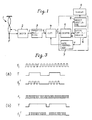
- Fig. 1 which illustrates in a block diagram one embodiment of the invention as applied to a balance, there is shown a vibration string 1, to which a load F placed on a weighing pan (not shown) of the balance is applied through a well known mechanism such as the Roberval type.
- a driver 2 such as the one disclosed in Japanese unexamined patent publication No. 60-207027 causes the string 1 to vibrate at its natural frequency f .
- the relation between the vibration frequency of the string 1 and the load or tension F applied thereto is given as the above-mentioned equation (1).
- the driver 2 produces a series of pulses at a frequency f in synchronism with the vibration of the string 1.
- the pulses f1 are applied to a gate 4.
- the gate 4 is controlled by a gate controller 7 so that the gate opens for a gating time T at a predetermined cycle thereby to allow the input pulses f1 to pass through the gate 4.
- the gating time T is variable in accordance with the command from the controller.
- the pulses f1′ that have passed through the gate 4 are applied to a counter 5, which counts the input pulses f1′ during the gating time T and applies the counted value y i to a gating time calculator 6 and a weight calculator 8.
- the counter 5 is reset each time the gating time T has elapsed.
- the weight calculator 8 calculates a load F on the basis of the counted values y i successively received from the counter 5 and subtracts the tare from the load in a well-known manner thereby to determine the weighed value of the sample being measured.
- the weighed value is displayed on a display 9.
- the gating time calculator 6 calculates a gating time T for the gate 4 in a manner to be described hereinbelow and applies the calculated time T to the gate controller 7, which controls the gate 4 so that the gate opens for the gating time T only.
- the counter 5, the gating time calculator 6, the gate controller 7 and the weight calculator 8 are composed of a microcomputer, which operates in accordance with a predetermined program such as shown in the flowchart of Fig. 2.
- the output pulses f1 from the frequency multiplier 3 are counted for the gating time T at step A1.
- the tension acting on the string 1, that is, the load F is calculated from the counted value y i by an equation to be given as (7) hereinbelow, and the tare is subtracted from the load to determine the weighed value, which is displayed on the display 9.
- the counted value y i is made a factor y i-1 for determining the gating time T for the next counting operation at step A3, and the next gating time T is calculated by the equation (3) at step A4.
- the microcomputer is provided with a plurality of operation keys, which are not shown in the figures, including a key for conducting the operation of subtracting the tare from the weighed value.
- a key for conducting the operation of subtracting the tare from the weighed value At step A5 the operating conditions of those keys are checked, and the next counted value y i is obtained again at step A1.
- the gating time T changes in proportion to the square root of the counted value y i-1 produced by the counter 5 in the previous counting operation.
- Fig. 3 shows the waveforms of the output signals from the circuits 3, 4 and 6 in Fig. 1. Under the condition shown in Fig. 3(a), as the load F is increased, the frequency f1 increases and at the same time the gating time T lengthens.
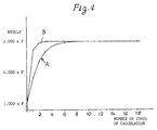
- the detector when the load has changed instantly from the initial value F to 2F, the detector responds to the change in the manner shown at A in Fig. 4, and when the operation has been repeated fifteen (15) times, the counted value y becomes 1.99996 ⁇ F, with the residual being 1/5 x 10 ⁇ 4. With a balance having an accuracy of 1/2 x 10 ⁇ 4, when the operation has been repeated fifteen times, the measured value becomes readable.
- the change of the counted value lags behind the change of the load or the vibration frequency of the string. This means that when the vibration frequency changes due to external disturbances, the change of the counted value is smaller than the change of the vibration frequency, with a resulting advantage that the device has the function of a digital filter.
- the difference p between the gating time that should be in accordance with the vibration frequency f0 of the string 1 and the present gating time may be used as a factor for determining the gating time.
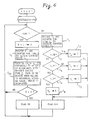
- Fig. 5 shows a flowchart of a program with the difference p used as a factor for determining the gating time T.
- the program of Fig. 5 differs from that of Fig. 2 in steps B1 and B4.
- the load changes from F to 2F upon repetition of the operation six times the counted value becomes 1.999970 x F, whereupon the measured value becomes readable on a balance having an accuracy of 1/2 x 10 ⁇ 4.
- the gating time T is changed in direct proportion to the square root of the counted value y i-1 .
- the invention is not limited to this way of changing the gating time, but the time T may be changed either in different proportional relationships with the counted value, or stepwise.
- Fig. 6 is a flowchart of a program in which the gating time T is changed stepwise.
- four different times Ta, Tb, Tc and Td corresponding to four predetermined different vibration frequency ranges of the string are preset, and the vibration frequency is measured periodically so that one of the times Ta ⁇ Td which corresponds to the measured frequency is selected as the gating time T.
- the pulses f1 are counted for a predetermined period of time T0, and the counted value y0 is compared successively with preset values a , b and c to determine the gating time.
- the value y0 is compared with the preset value a , and if y0 ⁇ a , the time Ta is selected as the gating time T at step C3. If y0>a , the value y0 is compared with the preset value b at step C4, and if y0 ⁇ b , the time Tb is selected as the gating time T at step C5.
- the value y0 is compared with the preset value c at step C6, and if y0 ⁇ c , the time Tc is selected as the gating time T at step C7. If y0>c , the time Td is selected as the gating time at C8.
- the pulses f1 produced during the gating time T selected in the above-mentioned manner are counted at step C9, and the weighed value of the object being measured is determined by the counted value y i at step C10.
- To convert the value y i to a corresponding weight it is necessary to use that one of predetermined conversion coefficients which corresponds to that one of the times Ta to Td which has been selected as the present gating time.
- the counted value y i to determine the weight cannot be obtained during the execution of the gating time selecting mode.
- another counter may be provided for counting the pulses f1 for the fixed gating time T0, so that the two counters are operated in parallel for counting the pulses f1.
- the pulses f produced by the driver 2 in synchronism with the vibration of the string 1 are multiplied by the multiplier 3 by a factor of k and the multiplied pulses f1 are counted so that the resolving power is improved substantially uniformly over the whole measuring range.
- the multiplier 3 may be omitted and the pulses f may be applied directly to the gate 4.
- the gating time for counting the vibration frequency of the string is lengthened as the frequency increases, so that it is possible to prevent deterioration of the resolving power which would otherwise be caused to occur by the increase of the force to be measured.
- the linearity may be further improved by additional compensation by the method of least squares or Lagrange's interpolation.
- the detector Since the detector is so constructed that the gating time for the present counting operation is determined by the counted value obtained by the preceeding counting operation, it has the function of a digital filter and is able to remove external disturbances. By changing the coefficient to determine the gating time it is possible to freely change the efficiency of the filter.
Landscapes
- Physics & Mathematics (AREA)
- General Physics & Mathematics (AREA)
- Measuring Frequencies, Analyzing Spectra (AREA)
- Force Measurement Appropriate To Specific Purposes (AREA)
- Indication And Recording Devices For Special Purposes And Tariff Metering Devices (AREA)
Claims (3)
- Kraftmesser vom Vibrationstyp mit einer Saite, auf die eine zu messende Kraft in der Richtung ausgeübt wird, in der die Feder gespannt ist; einem Treiber, der bewirkt, daß die Saite mit ihrer Eigenfrequenz schwingt, und der gleichzeitig eine Folge von Impulsen mit einer zu der Saitenschwingung synchronen Frequenz erzeugt; einem Schaltglied, dem die Impulsfolge zugeführt wird, und einem Zähler, der die das Schaltglied durchlaufenden Impulse zählt; dadurch gekennzeichnet, daß der Kraftmesser vom Vibrationstyp darüberhinaus eine Vorrichtung zum Bereitstellen einer entsprechend dem Zählergebnis des Zählers bestimmten Torzeit und eine Steuereinheit zum Steuern des Schaltgliedes entsprechend der Torzeit enthält, wobei die Vorrichtung zum Bereitstellen der Torzeit so beschaffen ist, daß sich die Torzeit mit zunehmender Schwingungsfrequenz der Saite verlängert.
- Kraftmesser nach Anspruch 1, der eine Multiplizierschaltung zum Vervielfachen der Frequenz der Impulsfolge enthält.
- Kraftmesser nach Anspruch 1, der eine Vorrichtung zum Berechnen der Größe der Kraft in Entsprechung zu dem Zählergebnis und eine Vorrichtung zum Anzeigen der Größe enthält.
Applications Claiming Priority (2)
| Application Number | Priority Date | Filing Date | Title |
|---|---|---|---|
| JP63248879A JPH0750001B2 (ja) | 1988-09-30 | 1988-09-30 | 弦振動式力測定器 |
| JP248879/88 | 1988-09-30 |
Publications (3)
| Publication Number | Publication Date |
|---|---|
| EP0361473A2 EP0361473A2 (de) | 1990-04-04 |
| EP0361473A3 EP0361473A3 (de) | 1991-10-09 |
| EP0361473B1 true EP0361473B1 (de) | 1993-06-02 |
Family
ID=17184792
Family Applications (1)
| Application Number | Title | Priority Date | Filing Date |
|---|---|---|---|
| EP89117951A Expired - Lifetime EP0361473B1 (de) | 1988-09-30 | 1989-09-28 | Kraftwandler mit schwingender Saite |
Country Status (4)
| Country | Link |
|---|---|
| US (1) | US4955240A (de) |
| EP (1) | EP0361473B1 (de) |
| JP (1) | JPH0750001B2 (de) |
| DE (1) | DE68906843T2 (de) |
Families Citing this family (2)
| Publication number | Priority date | Publication date | Assignee | Title |
|---|---|---|---|---|
| CZ2006439A3 (cs) * | 2006-07-03 | 2007-09-26 | Ceské vysoké ucení technické v Praze Fakulta elektrotechnická | Zarízení pro kontinuální merení kmitu strunových tenzometrických snímacu s dvouvodicovým pripojením |
| CZ300136B6 (cs) * | 2008-07-03 | 2009-02-18 | Ceské vysoké ucení technické v Praze Fakulta elektrotechnická | Zarízení pro kontinuální merení kmitu strunových tenzometrických snímacu s dvouvodicovým pripojením |
Family Cites Families (3)
| Publication number | Priority date | Publication date | Assignee | Title |
|---|---|---|---|---|
| CH536488A (de) * | 1971-08-19 | 1973-04-30 | Mettler Instrumente Ag | Kraftmesser |
| US4194649A (en) * | 1977-06-06 | 1980-03-25 | K-Tron International, Inc. | Weigh feeder |
| US4418774A (en) * | 1981-12-08 | 1983-12-06 | Franklin Electric Co., Inc. | Weight or force measuring apparatus |
-
1988
- 1988-09-30 JP JP63248879A patent/JPH0750001B2/ja not_active Expired - Lifetime
-
1989
- 1989-09-26 US US07/412,428 patent/US4955240A/en not_active Expired - Fee Related
- 1989-09-28 EP EP89117951A patent/EP0361473B1/de not_active Expired - Lifetime
- 1989-09-28 DE DE8989117951T patent/DE68906843T2/de not_active Expired - Fee Related
Also Published As
| Publication number | Publication date |
|---|---|
| DE68906843D1 (de) | 1993-07-08 |
| JPH0750001B2 (ja) | 1995-05-31 |
| EP0361473A2 (de) | 1990-04-04 |
| US4955240A (en) | 1990-09-11 |
| EP0361473A3 (de) | 1991-10-09 |
| DE68906843T2 (de) | 1993-09-23 |
| JPH0295226A (ja) | 1990-04-06 |
Similar Documents
| Publication | Publication Date | Title |
|---|---|---|
| EP0171237B2 (de) | Waage mit Kriechfehlerausgleich | |
| US4156472A (en) | Apparatus for automatically changing the integration time and resolution of an electrical scale under predetermined operating conditions | |
| GB2189319A (en) | Temperature compensation of force measuring apparatus | |
| CA1082366A (en) | Method and apparatus for determining weight and mass | |
| US4404638A (en) | Flow rate measuring device | |
| US3885427A (en) | Electronic balance for measuring masses or forces | |
| CA1097703A (en) | Scale with digital display | |
| EP0361473B1 (de) | Kraftwandler mit schwingender Saite | |
| US3565193A (en) | Electrical weigher using vibrating strings | |
| CA1094586A (en) | Scale, in particular for weighing bulk goods | |
| US4512429A (en) | Weighing apparatus for producing geographically-corrected measurements | |
| EP0454916A1 (de) | Vorrichtung zum Kompensieren von einem zeitabhängigen Kriechfehler und eines ähnlichen Messgerätes | |
| GB2155190A (en) | Counting by weighing | |
| JP3120883B2 (ja) | 計数秤 | |
| JPH0532684B2 (de) | ||
| KR910001147B1 (ko) | 계량장치 | |
| JPH0346765B2 (de) | ||
| JPS6244601B2 (de) | ||
| RU2037793C1 (ru) | Электронный преобразователь силы для весов | |
| JPS5855821A (ja) | 電子計数はかり | |
| JPH08110261A (ja) | 質量計量装置及び重量計量装置 | |
| JPS626492Y2 (de) | ||
| JPS5895220A (ja) | コンベヤスケ−ルのスパン調整方法 | |
| SU514208A1 (ru) | Весовое устройство с вычислением стоимости взвешенного товара | |
| KR960016094B1 (ko) | 전자레인지용 미세중량감지표시방법 |
Legal Events
| Date | Code | Title | Description |
|---|---|---|---|
| PUAI | Public reference made under article 153(3) epc to a published international application that has entered the european phase |
Free format text: ORIGINAL CODE: 0009012 |
|
| AK | Designated contracting states |
Kind code of ref document: A2 Designated state(s): CH DE FR GB LI |
|
| 17P | Request for examination filed |
Effective date: 19901231 |
|
| PUAL | Search report despatched |
Free format text: ORIGINAL CODE: 0009013 |
|
| AK | Designated contracting states |
Kind code of ref document: A3 Designated state(s): CH DE FR GB LI |
|
| 17Q | First examination report despatched |
Effective date: 19920921 |
|
| GRAA | (expected) grant |
Free format text: ORIGINAL CODE: 0009210 |
|
| AK | Designated contracting states |
Kind code of ref document: B1 Designated state(s): CH DE FR GB LI |
|
| REF | Corresponds to: |
Ref document number: 68906843 Country of ref document: DE Date of ref document: 19930708 |
|
| ET | Fr: translation filed | ||
| PLBE | No opposition filed within time limit |
Free format text: ORIGINAL CODE: 0009261 |
|
| STAA | Information on the status of an ep patent application or granted ep patent |
Free format text: STATUS: NO OPPOSITION FILED WITHIN TIME LIMIT |
|
| 26N | No opposition filed | ||
| PGFP | Annual fee paid to national office [announced via postgrant information from national office to epo] |
Ref country code: FR Payment date: 19950911 Year of fee payment: 7 |
|
| REG | Reference to a national code |
Ref country code: GB Ref legal event code: 746 Effective date: 19950810 |
|
| PGFP | Annual fee paid to national office [announced via postgrant information from national office to epo] |
Ref country code: GB Payment date: 19950919 Year of fee payment: 7 |
|
| PGFP | Annual fee paid to national office [announced via postgrant information from national office to epo] |
Ref country code: DE Payment date: 19950928 Year of fee payment: 7 |
|
| PGFP | Annual fee paid to national office [announced via postgrant information from national office to epo] |
Ref country code: CH Payment date: 19951020 Year of fee payment: 7 |
|
| REG | Reference to a national code |
Ref country code: FR Ref legal event code: D6 |
|
| PG25 | Lapsed in a contracting state [announced via postgrant information from national office to epo] |
Ref country code: GB Effective date: 19960928 |
|
| PG25 | Lapsed in a contracting state [announced via postgrant information from national office to epo] |
Ref country code: LI Effective date: 19960930 Ref country code: FR Effective date: 19960930 Ref country code: CH Effective date: 19960930 |
|
| REG | Reference to a national code |
Ref country code: CH Ref legal event code: PL |
|
| GBPC | Gb: european patent ceased through non-payment of renewal fee |
Effective date: 19960928 |
|
| PG25 | Lapsed in a contracting state [announced via postgrant information from national office to epo] |
Ref country code: DE Effective date: 19970603 |
|
| REG | Reference to a national code |
Ref country code: FR Ref legal event code: ST |
|
| REG | Reference to a national code |
Ref country code: FR Ref legal event code: ST |