EP0361528A2 - Carter de palier - Google Patents
Carter de palier Download PDFInfo
- Publication number
- EP0361528A2 EP0361528A2 EP89118194A EP89118194A EP0361528A2 EP 0361528 A2 EP0361528 A2 EP 0361528A2 EP 89118194 A EP89118194 A EP 89118194A EP 89118194 A EP89118194 A EP 89118194A EP 0361528 A2 EP0361528 A2 EP 0361528A2
- Authority
- EP
- European Patent Office
- Prior art keywords
- bearing housing
- housing according
- bearing
- following
- ribs
- Prior art date
- Legal status (The legal status is an assumption and is not a legal conclusion. Google has not performed a legal analysis and makes no representation as to the accuracy of the status listed.)
- Granted
Links
Images


Classifications
-
- F—MECHANICAL ENGINEERING; LIGHTING; HEATING; WEAPONS; BLASTING
- F16—ENGINEERING ELEMENTS AND UNITS; GENERAL MEASURES FOR PRODUCING AND MAINTAINING EFFECTIVE FUNCTIONING OF MACHINES OR INSTALLATIONS; THERMAL INSULATION IN GENERAL
- F16C—SHAFTS; FLEXIBLE SHAFTS; ELEMENTS OR CRANKSHAFT MECHANISMS; ROTARY BODIES OTHER THAN GEARING ELEMENTS; BEARINGS
- F16C35/00—Rigid support of bearing units; Housings, e.g. caps, covers
-
- F—MECHANICAL ENGINEERING; LIGHTING; HEATING; WEAPONS; BLASTING
- F04—POSITIVE - DISPLACEMENT MACHINES FOR LIQUIDS; PUMPS FOR LIQUIDS OR ELASTIC FLUIDS
- F04D—NON-POSITIVE-DISPLACEMENT PUMPS
- F04D29/00—Details, component parts, or accessories
- F04D29/40—Casings; Connections of working fluid
- F04D29/42—Casings; Connections of working fluid for radial or helico-centrifugal pumps
- F04D29/426—Casings; Connections of working fluid for radial or helico-centrifugal pumps especially adapted for liquid pumps
Definitions
- the invention relates to a bearing housing for fluid pumps, for example cooling pumps on vehicle engines or the like. Which is connected to the engine block or the like.
- bearing housings are known per se and have become known, for example, from US / PS 3723029 and 3778181.
- US / PS 1649329 also shows a bearing housing for water pumps for internal combustion engines.
- These bearing housings are made of metallic materials. In the course of saving weight and also for reasons of corrosion, the demand for plastic parts in vehicle construction is constantly increasing.
- the invention seeks to remedy this.
- the invention solves the problem of having a bearing housing made of plastic with an exchangeable bearing and sealing cassette which can absorb mechanical, thermal, corrosion and hydrolysis loads and has a sufficient service life.
- the advantages achieved by the invention are essentially to be seen in the fact that the moments acting on the bearing cylinder via the bearing due to input and output forces via ribs from the bearing cylinder be introduced into a flange collar located in the flange area thereof, this flange collar introducing the statically and dynamically acting tensile / compressive forces into the flange eyes serving as fastening.
- the stiffness in relation to force peaks and vibrations or acceleration forces can be predetermined by varying the height, shape and thickness of the flange collar, the bearing cylinder and the ribs or web arrangements.
- Another advantage of the bearing housing designed according to the invention can be seen in that the leakage water is drained off via a drainage channel and an evaporation chamber. Another advantage is that the cavitation behavior of plastics is better than that of metallic materials.
- an axial lock is provided for the bearing cylinder.
- the bearing is also used as a load-bearing element in that it absorbs static forces, such as bending forces, together with the bearing cylinder.
- An embodiment variant provides that the bearing housing is connected to the bearing housing via a web, which can be either ring-shaped or oblique or conical.
- the flow conditions of the fluid can also be influenced by an oblique and / or conical shape of the web. It is also advantageous that the dismantling ability of the entire unit is fully retained. Another advantage is that the compensation of the different thermal expansion of the sealing element and plastic housing of the bearing cylinder in the region of the seat of the sealing element tes takes place via an O-ring and thus the usual use of a sealing lacquer or the like. Can be dispensed with, the security is still increased.
- a bearing housing for fluid pumps and correspondingly acting devices is shown, the basic structure of which consists of a housing with the actual flange collar 1 above a shoulder 1a, below which there is a groove 1b for receiving a sealant and which is directed downward towards the housing part 1d is delimited by a projection 1c.
- the bearing cylinder 2 is connected via a connecting ring 3 to the lower housing part 1d, the end part of which is designated 1e and serves to receive the bearing cylinder.
- Several flange eyes 4 (4a, 4c, 4d, 4f) distributed over the circumference of the flange collar 1 serve to fasten the bearing housing to the engine block, for example, which is not shown in the figures.
- the threaded flange eyes 4b and 4e serve for easier dismantling of the bearing housing.
- With 5 is a stop for the bearing and a sealing cartridge inserted below it.
- Excess fluid, lubricant, etc. is supplied to the evaporator chamber 6a via the drainage channel 6c.
- This evaporator chamber 6a can either be an integrated part of the bearing housing or can be used as a separate part.
- the evaporator chamber, on the one hand, if it is integrated in the bearing housing, is formed by the outer jacket of the bearing cylinder 2 and, on the other hand, by a wall 6b.
- the bearing cylinder 2 has an undercut 2c in its upper part, into which an axial securing element K, for example a snap ring and the like, can be inserted.
- the bearing cylinder 2 is surrounded by a plurality of radially extending, axially extending ribs 7 (7a to 7j) which are rooted on the connecting ring 3 and protrude into the flange collar 1 and the flange eyes 4.
- the two ribs 7a and 7b simultaneously form the lateral boundary of the evaporator chamber 6a.
- the ribs 7 can either be connected to the flange eyes or connected directly to the flange collar 1.
- the ribs 7 themselves are designed to run conically upwards from the end of the flange collar 1 to the end of the bearing cylinder. These ribs 7 can either end at the end of the bearing cylinder 2 or shortly before.
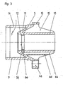
- FIG. 3 shows an embodiment variant of FIG. 1 with a conical connecting web 11, which can also be shaped asymmetrically in order to improve the flow of the fluid.
- the fulcrum 12 of the Bearing cylinder 10 is relocated at the beginning and thus greater stabilization in the sealing element area is achieved.
- the ribs 15 (15a, 15b) are also distributed over the circumference of the bearing cylinder 10. They are connected on the one hand to the outer circumference of the bearing cylinder 10 and on the other hand to the cone 11 and the flange collar 13, while the rest of the rib remains without limitation. 14 with an opening provided in the lower part 9 for the fluid F. The fluid flowing into the housing 9 through this opening 14 strikes the conical outer wall of the connecting web 11 and is drawn in a streamlined manner through the impeller (not shown).
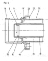
- FIG. 4 shows a further embodiment variant of FIGS. 1 and 3.
- the bearing cylinder 17 is surrounded concentrically by another cylinder 20.
- the ribs 21 are arranged between the two cylinders 17 and 20, for example radially. Ribs are provided between the outer cylinder 20 and the flange ring 23. The ribs 21 protrude up to the connecting web 19, which can also be conical, oblique, etc., for example.
- the evaporator chamber 6a is provided with its drainage channel 6c.
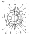
- FIG. 5 illustrates in a top view the arrangement of the ribs 7, which, like for example the ribs 24 and 25 and 26 and 27, also does not show one radial course between the bearing cylinder 2 or 10 or 17 can take.
- Arrangements as shown in FIG. 6 are also possible, there the ribs 30 and 31 are provided with the ribs 29 and 32 in the direction of the center of the arrangement.
- the ribs 34, 35 open into the ribs 33, 36 and the flange eyes 4a run indirectly via these ribs 33, 36 and the bearing cylinder.
- These rib arrangements or the rib arrangement according to FIG. 5 can also be combined as required. It is also possible to combine the variants of the rib design and the connecting web 3 or 11 shown in the figures, for example.
- the part of the bearing housing which contains the bearing cylinder 2 or 10, 17 can also be used without the actual lower part 1d or 9 or 16.
- the guide ring L of the impeller can also be part of the lower part (1d) of the housing in this area
Landscapes
- Engineering & Computer Science (AREA)
- General Engineering & Computer Science (AREA)
- Mechanical Engineering (AREA)
- Structures Of Non-Positive Displacement Pumps (AREA)
- Mounting Of Bearings Or Others (AREA)
- Sliding-Contact Bearings (AREA)
- Support Of The Bearing (AREA)
Applications Claiming Priority (2)
| Application Number | Priority Date | Filing Date | Title |
|---|---|---|---|
| DE3833331A DE3833331A1 (de) | 1988-09-30 | 1988-09-30 | Lagergehaeuse |
| DE3833331 | 1988-09-30 |
Publications (3)
| Publication Number | Publication Date |
|---|---|
| EP0361528A2 true EP0361528A2 (fr) | 1990-04-04 |
| EP0361528A3 EP0361528A3 (en) | 1990-08-08 |
| EP0361528B1 EP0361528B1 (fr) | 1996-05-15 |
Family
ID=6364119
Family Applications (1)
| Application Number | Title | Priority Date | Filing Date |
|---|---|---|---|
| EP89118194A Expired - Lifetime EP0361528B1 (fr) | 1988-09-30 | 1989-09-30 | Carter de palier |
Country Status (5)
| Country | Link |
|---|---|
| EP (1) | EP0361528B1 (fr) |
| JP (1) | JPH02199216A (fr) |
| AT (1) | ATE138162T1 (fr) |
| CA (1) | CA1337210C (fr) |
| DE (2) | DE3833331A1 (fr) |
Cited By (1)
| Publication number | Priority date | Publication date | Assignee | Title |
|---|---|---|---|---|
| AT409530B (de) * | 1999-04-29 | 2002-09-25 | Tcg Unitech Ag | Kühlwasserpumpe für eine brennkraftmaschine |
Families Citing this family (2)
| Publication number | Priority date | Publication date | Assignee | Title |
|---|---|---|---|---|
| DE4423588C1 (de) * | 1994-07-06 | 1995-07-20 | Daimler Benz Ag | Verfahren zur Herstellung eines Achslager-Lagergehäuse-Verbunds |
| JP5477585B2 (ja) * | 2010-04-16 | 2014-04-23 | スズキ株式会社 | エンジンのウォータポンプ装置 |
Family Cites Families (7)
| Publication number | Priority date | Publication date | Assignee | Title |
|---|---|---|---|---|
| GB1258074A (fr) * | 1968-03-18 | 1971-12-22 | ||
| DE2109341A1 (de) * | 1970-03-17 | 1971-11-04 | Standard Magnet Ag | Kühlwasserpumpe für Automobile |
| US3778181A (en) * | 1971-03-24 | 1973-12-11 | Gorman Rupp Co | Centrifugal pump |
| DE2330671A1 (de) * | 1973-06-16 | 1975-01-02 | Luk Lamellen & Kupplungsbau | Wasserpumpenaggregat fuer brennkraftmaschinen |
| DE2846950C2 (de) * | 1978-10-27 | 1980-01-24 | Bayerische Motoren Werke Ag, 8000 Muenchen | Kühlmiftelpumpe für flüssigkeitsgekühlte Brennkraftmaschinen |
| DE8133158U1 (de) * | 1980-11-28 | 1982-05-06 | RIV-SKF Officine di Villar Perosa S.p.A., 10123 Torino | "integrale pumpeneinheit fuer kreiselpumpen" |
| JPH027278Y2 (fr) * | 1984-09-10 | 1990-02-21 |
-
1988
- 1988-09-30 DE DE3833331A patent/DE3833331A1/de not_active Ceased
-
1989
- 1989-09-28 JP JP1250792A patent/JPH02199216A/ja active Pending
- 1989-09-29 CA CA000615019A patent/CA1337210C/fr not_active Expired - Fee Related
- 1989-09-30 DE DE58909679T patent/DE58909679D1/de not_active Expired - Fee Related
- 1989-09-30 EP EP89118194A patent/EP0361528B1/fr not_active Expired - Lifetime
- 1989-09-30 AT AT89118194T patent/ATE138162T1/de not_active IP Right Cessation
Cited By (1)
| Publication number | Priority date | Publication date | Assignee | Title |
|---|---|---|---|---|
| AT409530B (de) * | 1999-04-29 | 2002-09-25 | Tcg Unitech Ag | Kühlwasserpumpe für eine brennkraftmaschine |
Also Published As
| Publication number | Publication date |
|---|---|
| EP0361528B1 (fr) | 1996-05-15 |
| DE58909679D1 (de) | 1996-06-20 |
| EP0361528A3 (en) | 1990-08-08 |
| DE3833331A1 (de) | 1990-04-05 |
| JPH02199216A (ja) | 1990-08-07 |
| ATE138162T1 (de) | 1996-06-15 |
| CA1337210C (fr) | 1995-10-03 |
Similar Documents
| Publication | Publication Date | Title |
|---|---|---|
| DE2908189C2 (fr) | ||
| DE10064482B4 (de) | Filteranordnung für Flüssigkeiten | |
| EP1671031B1 (fr) | Pompe a fluide, en particulier pompe a carburant haute pression | |
| DE69326985T2 (de) | Brennstoffeinspritzventil mit hochdruckbegrenzungsventil | |
| DE10259808B4 (de) | Strahlpumpe | |
| EP0699826A1 (fr) | Circuit de liquide avec un filtre au courant principal | |
| DE3633487C2 (fr) | ||
| EP1960653A1 (fr) | Piston en deux pieces pour moteur a combustion interne | |
| DE3871790T2 (de) | Ventil fuer fluid. | |
| DE10334762A1 (de) | Zentrifugenrotor mit Niederdruckabsperrung und Kapazitätssensor | |
| EP1123461B1 (fr) | Injecteur de structure compacte pour systeme d'injection a rampe commune de moteur a combustion interne | |
| DE2131117A1 (de) | Fluessigkeitsmengenregler | |
| EP1068443B1 (fr) | Soupape de pression | |
| EP0021315B1 (fr) | Machine à piston, notamment pompe à piston | |
| EP0361528A2 (fr) | Carter de palier | |
| EP1554487A1 (fr) | Dispositif d'injection de carburant d'un moteur a combustion interne | |
| DE69816906T2 (de) | Befestigungsflansch eines Einspritzventils | |
| DE3141654A1 (de) | Kraftstoffeinspritzpumpe, insbesondere fuer eine dieselbrennkraftmaschine | |
| EP1660769B1 (fr) | Piston en plusieurs parties destine a un moteur a combustion interne | |
| EP1819921B1 (fr) | Piston d'un moteur a combustion interne | |
| EP0949446B1 (fr) | Corps de soupape avec un raccord et un capot | |
| DE3702272A1 (de) | Tauchkolben fuer verbrennungsmotoren mit einem von kuehloel durchstroemten hohlraum | |
| DE3820706A1 (de) | Einspritzpumpe fuer brennkraftmaschinen | |
| DE3303856A1 (de) | Pumpe | |
| EP0961015B1 (fr) | Pompe a huile et pompe de refroidissement pour un moteur a combustion interne |
Legal Events
| Date | Code | Title | Description |
|---|---|---|---|
| PUAI | Public reference made under article 153(3) epc to a published international application that has entered the european phase |
Free format text: ORIGINAL CODE: 0009012 |
|
| AK | Designated contracting states |
Kind code of ref document: A2 Designated state(s): AT BE CH DE ES FR GB GR IT LI LU NL SE |
|
| PUAL | Search report despatched |
Free format text: ORIGINAL CODE: 0009013 |
|
| AK | Designated contracting states |
Kind code of ref document: A3 Designated state(s): AT BE CH DE ES FR GB GR IT LI LU NL SE |
|
| 17P | Request for examination filed |
Effective date: 19900925 |
|
| 17Q | First examination report despatched |
Effective date: 19911126 |
|
| 18D | Application deemed to be withdrawn |
Effective date: 19931021 |
|
| D18D | Application deemed to be withdrawn (deleted) | ||
| GRAH | Despatch of communication of intention to grant a patent |
Free format text: ORIGINAL CODE: EPIDOS IGRA |
|
| GRAA | (expected) grant |
Free format text: ORIGINAL CODE: 0009210 |
|
| AK | Designated contracting states |
Kind code of ref document: B1 Designated state(s): AT BE CH DE ES FR GB GR IT LI LU NL SE |
|
| PG25 | Lapsed in a contracting state [announced via postgrant information from national office to epo] |
Ref country code: IT Free format text: LAPSE BECAUSE OF FAILURE TO SUBMIT A TRANSLATION OF THE DESCRIPTION OR TO PAY THE FEE WITHIN THE PRESCRIBED TIME-LIMIT;WARNING: LAPSES OF ITALIAN PATENTS WITH EFFECTIVE DATE BEFORE 2007 MAY HAVE OCCURRED AT ANY TIME BEFORE 2007. THE CORRECT EFFECTIVE DATE MAY BE DIFFERENT FROM THE ONE RECORDED. Effective date: 19960515 Ref country code: GB Effective date: 19960515 Ref country code: GR Free format text: LAPSE BECAUSE OF FAILURE TO SUBMIT A TRANSLATION OF THE DESCRIPTION OR TO PAY THE FEE WITHIN THE PRESCRIBED TIME-LIMIT Effective date: 19960515 Ref country code: NL Free format text: LAPSE BECAUSE OF FAILURE TO SUBMIT A TRANSLATION OF THE DESCRIPTION OR TO PAY THE FEE WITHIN THE PRESCRIBED TIME-LIMIT Effective date: 19960515 Ref country code: FR Effective date: 19960515 Ref country code: ES Free format text: THE PATENT HAS BEEN ANNULLED BY A DECISION OF A NATIONAL AUTHORITY Effective date: 19960515 Ref country code: BE Effective date: 19960515 |
|
| REF | Corresponds to: |
Ref document number: 138162 Country of ref document: AT Date of ref document: 19960615 Kind code of ref document: T |
|
| REF | Corresponds to: |
Ref document number: 58909679 Country of ref document: DE Date of ref document: 19960620 |
|
| PG25 | Lapsed in a contracting state [announced via postgrant information from national office to epo] |
Ref country code: SE Effective date: 19960815 |
|
| PG25 | Lapsed in a contracting state [announced via postgrant information from national office to epo] |
Ref country code: CH Effective date: 19960930 Ref country code: LI Effective date: 19960930 Ref country code: LU Free format text: LAPSE BECAUSE OF NON-PAYMENT OF DUE FEES Effective date: 19960930 Ref country code: AT Effective date: 19960930 |
|
| EN | Fr: translation not filed | ||
| NLV1 | Nl: lapsed or annulled due to failure to fulfill the requirements of art. 29p and 29m of the patents act | ||
| GBV | Gb: ep patent (uk) treated as always having been void in accordance with gb section 77(7)/1977 [no translation filed] |
Effective date: 19960515 |
|
| PLBE | No opposition filed within time limit |
Free format text: ORIGINAL CODE: 0009261 |
|
| STAA | Information on the status of an ep patent application or granted ep patent |
Free format text: STATUS: NO OPPOSITION FILED WITHIN TIME LIMIT |
|
| 26N | No opposition filed | ||
| REG | Reference to a national code |
Ref country code: CH Ref legal event code: PL |
|
| PGFP | Annual fee paid to national office [announced via postgrant information from national office to epo] |
Ref country code: DE Payment date: 19990730 Year of fee payment: 11 |
|
| PG25 | Lapsed in a contracting state [announced via postgrant information from national office to epo] |
Ref country code: DE Free format text: LAPSE BECAUSE OF NON-PAYMENT OF DUE FEES Effective date: 20010601 |