EP0361535B1 - Blattmaterial, bestehend aus mindestens drei Papierschichten - Google Patents
Blattmaterial, bestehend aus mindestens drei Papierschichten Download PDFInfo
- Publication number
- EP0361535B1 EP0361535B1 EP89119981A EP89119981A EP0361535B1 EP 0361535 B1 EP0361535 B1 EP 0361535B1 EP 89119981 A EP89119981 A EP 89119981A EP 89119981 A EP89119981 A EP 89119981A EP 0361535 B1 EP0361535 B1 EP 0361535B1
- Authority
- EP
- European Patent Office
- Prior art keywords
- layers
- impressions
- encasing
- layer
- container
- Prior art date
- Legal status (The legal status is an assumption and is not a legal conclusion. Google has not performed a legal analysis and makes no representation as to the accuracy of the status listed.)
- Expired - Lifetime
Links
Images


Classifications
-
- B—PERFORMING OPERATIONS; TRANSPORTING
- B65—CONVEYING; PACKING; STORING; HANDLING THIN OR FILAMENTARY MATERIAL
- B65D—CONTAINERS FOR STORAGE OR TRANSPORT OF ARTICLES OR MATERIALS, e.g. BAGS, BARRELS, BOTTLES, BOXES, CANS, CARTONS, CRATES, DRUMS, JARS, TANKS, HOPPERS, FORWARDING CONTAINERS; ACCESSORIES, CLOSURES, OR FITTINGS THEREFOR; PACKAGING ELEMENTS; PACKAGES
- B65D31/00—Bags or like containers made of paper and having structural provision for thickness of contents
- B65D31/04—Bags or like containers made of paper and having structural provision for thickness of contents with multiple walls
-
- B—PERFORMING OPERATIONS; TRANSPORTING
- B65—CONVEYING; PACKING; STORING; HANDLING THIN OR FILAMENTARY MATERIAL
- B65D—CONTAINERS FOR STORAGE OR TRANSPORT OF ARTICLES OR MATERIALS, e.g. BAGS, BARRELS, BOTTLES, BOXES, CANS, CARTONS, CRATES, DRUMS, JARS, TANKS, HOPPERS, FORWARDING CONTAINERS; ACCESSORIES, CLOSURES, OR FITTINGS THEREFOR; PACKAGING ELEMENTS; PACKAGES
- B65D33/00—Details of, or accessories for, sacks or bags
- B65D33/06—Handles
- B65D33/12—String handles
-
- B—PERFORMING OPERATIONS; TRANSPORTING
- B31—MAKING ARTICLES OF PAPER, CARDBOARD OR MATERIAL WORKED IN A MANNER ANALOGOUS TO PAPER; WORKING PAPER, CARDBOARD OR MATERIAL WORKED IN A MANNER ANALOGOUS TO PAPER
- B31B—MAKING CONTAINERS OF PAPER, CARDBOARD OR MATERIAL WORKED IN A MANNER ANALOGOUS TO PAPER
- B31B70/00—Making flexible containers, e.g. envelopes or bags
- B31B70/74—Auxiliary operations
- B31B70/81—Forming or attaching accessories, e.g. opening devices, closures or tear strings
- B31B70/813—Applying closures
- B31B70/8134—Applying strings; Making string-closed bags
-
- Y—GENERAL TAGGING OF NEW TECHNOLOGICAL DEVELOPMENTS; GENERAL TAGGING OF CROSS-SECTIONAL TECHNOLOGIES SPANNING OVER SEVERAL SECTIONS OF THE IPC; TECHNICAL SUBJECTS COVERED BY FORMER USPC CROSS-REFERENCE ART COLLECTIONS [XRACs] AND DIGESTS
- Y10—TECHNICAL SUBJECTS COVERED BY FORMER USPC
- Y10S—TECHNICAL SUBJECTS COVERED BY FORMER USPC CROSS-REFERENCE ART COLLECTIONS [XRACs] AND DIGESTS
- Y10S493/00—Manufacturing container or tube from paper; or other manufacturing from a sheet or web
- Y10S493/916—Pliable container
- Y10S493/926—Pliable container having handle or suspension means
-
- Y—GENERAL TAGGING OF NEW TECHNOLOGICAL DEVELOPMENTS; GENERAL TAGGING OF CROSS-SECTIONAL TECHNOLOGIES SPANNING OVER SEVERAL SECTIONS OF THE IPC; TECHNICAL SUBJECTS COVERED BY FORMER USPC CROSS-REFERENCE ART COLLECTIONS [XRACs] AND DIGESTS
- Y10—TECHNICAL SUBJECTS COVERED BY FORMER USPC
- Y10T—TECHNICAL SUBJECTS COVERED BY FORMER US CLASSIFICATION
- Y10T428/00—Stock material or miscellaneous articles
- Y10T428/24—Structurally defined web or sheet [e.g., overall dimension, etc.]
- Y10T428/24628—Nonplanar uniform thickness material
- Y10T428/24661—Forming, or cooperating to form cells
Definitions
- the present invention relates to a sheet piece consisting of at least three material layers of paper forming, for example, an encasing wall of a portable container.
- An insulating sheet made up of at least two layers of a plastic material which are heat sealed is known from DE-A-2 035 449. At least one of the plastic layers is provided with a large number of uniformly distributed localized impressions which, together with the remaining layers, form closed cells.
- the purpose of the present invention is to provide a sheet piece, forming a stable heat and cold isolating wall by utilizing low cost paper sheets.
- a sheet piece intended to form, for example, an encasing wall of a portable container, consisting of at least three material layers of paper, each of which extends in a principle plane and is provided with a large number of localized impressions with spaces therebetween distributed uniformly over the surface of the layer, said impressions extending from the principle plane of every layer in the same direction normal to said principle planes, the layers being placed relative to each other in such a manner that, in the direction normal to said principle planes, the impressions in one layer are located directly in front of the spaces in adjacent layers and each of the layers is joined with its adjacent layer or layers by means of an adhesive, whereby a large number of closed cells are created, so that at most two layers are directly joined together with each other.
- fig. 1 shows an example of a portable container built up by means of sheet pieces according to the present invention
- fig. 2 illustrates a continuous material web of sheet pieces according to the present invention forming partially completed containers
- figs. 3 and 4 show a partially broken perspective view of an upper section of the container in its open and its closed configuration, respectively
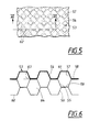
- fig. 5 illustrates a broken view, in enlarged scale, of a portion of a sheet piece forming encasing walls of the container
- fig. 6 shows schematically a cross sectional view in even greater scale taken along the line VI-VI in fig. 5.
- the container 1 consists mainly of a handle member 2 and an encasing member 3, which is intended to contain the object or objects, which are to be carried using the container.
- the encasing member 3 consists mainly of two oppositely positioned encasing walls which consist of said sheet pieces and are joined along the side edge sections 4 and 5 of the container and the bottom edge section 6.
- the walls are made of a paper material which gives the container a certain stability while at the same time making the container shapeable so that a space is created between the two walls into which the object in question may be placed.
- the handle member 2 consists of a single handle, fastened at the edge of the opening section 7 of one of the two walls.
- the container has an opening which is delimited by the opening edge section 7 of the two walls.
- the opening may be closed by applying to the edge of the opening section of each of the walls an adhesive substance, so that the edges of the opening sections of the respective walls, when pressed together, adhere to one another.
- An example of the attachment of the handle member and also a method and a machine for such an attachment is shown in the application No 86850329.3 from which the present application is divided.
- Fig. 2 shows container material in the form of a continuous material web 22 consisting of one or several layers of paper extending over the full width of the web with paper strips 30, attached by means of adhesive, along both edge sections 41 of the material web and strings 28 applied in the form of loops between the material web and the strips 30.
- the handle loops are formed with a desired relative separation whereby the string is allowed to run through the bottom of the container to which it will thereby provide a certain degree of reinforcement. Also a certain degree of reinforcement is provided by the paper strip 30 in the bottom of the containers.
- a separate device will join the material web 22 along with the handle members and strip 30 to the material web which is to form the container's opposite wall and which has been provided with glue in accordance with some predetermined pattern so that the material webs may be glued together along the side edge sections 3 and 4 and the bottom edge section 6 whereupon separate containers will be obtained by means of cutting along the lines 46. At this point the strings will also be cut at their points of intersection with the lines 46.
- Two sections 48 of the handle member 2 are consequently affixed between one of the layers of material 22 and the strip 30. Each of these sections consists of a first portion 50 and a second portion 51, positioned at an angle to the first portion.
- Figs. 3 and 4 show clearly how the upper section of the container is constructed and how it may be closed.
- the container is provided with a single handle member 2 which is secured to the opening edge section 7 of one of the encasing walls.
- Fig. 3 shows how the container appears when it contains some object which is to be carried, whereby the flexible encasing walls are bent away from each other between the side edge sections 4 and 5 so that an opening 52 is created, through which the intended contents of the container can be inserted.
- the encasing wall which does not have a handle member at the top is arranged with an edge 47 folded down, which is provided with a fastening surface which consequently faces outwards from the folded down edge.
- the folded down edge 47 When closing the container the folded down edge 47 is folded up and its fastening surface is pressed against the inside of the opposite opening edge section 7 which is provided with a surface made self-adhesive by means of a suitably chosen glue, so that the container assumes the general appearance shown in fig. 4, after that an object to be carried has been inserted into the space, enclosed by means of the encasing walls 53.
- the handle member 2 In addition to closing the opening 52 the handle member 2 will hereby be anchored to both of the encasing walls opening edge sections 7 by means of the joining of the two said opening edge sections so that a uniform tension load arises in the container when it is lifted by means of the handle member 2.
- the fastening surface of the folded down edge 47 may also be provided with a self-adhesive material.
- the container is made heat insulating by means of fashioning each of the encasing walls 53 out of at least three material layers, generally of paper, which are so embossed that they together form an encasing wall, the thickness of which is considerably greater than the sum of the thicknesses of each of the material layers (see figs. 5 and 6). It is advantageous to form the one material layer 54, which comprises an outer material layer of the encasing wall, of a paper which has a thickness considerably greater than the other material layers 55 and 56.
- the impressions 57 may be considered to be viewed from the outer layer 54, so that the impressions 57 consist of areas raised above the main plane 58. These raised areas 57, as well as the impressions in the other layers, are distributed uniformly over the entire surface of the encasing walls 53 with predetermined separation, so that spaces are created between the impressions 57, which generally correspond to or somewhat exceed the dimension of the impressions 57. These may assume a variety of different shapes and in the given example the bottom surface 61 of the impressions are shown as being square, however even polygonal or circular shapes are conceivable.
- the impressions 57 are arranged so as to form rows extending diagonally which, in the given example, implies a direction of 45° relative to the vertical or longitudinal axis of the container, so that the corners of the impressed surfaces are oriented in the direction of said axes.
- Both of the other material layers i.e., the middle layer 55 and the inner layer 56, are also provided with impressions, suitably aligned in the same direction as the impressions in the outer layer.
- the impressions of the inner layer are located coincidentally with those of the outer layer when viewed from the side of the encasing walls, i.e., according to fig. 5, whereas the impressions of the middle layer 55 are displaced in the direction formed by the diagonals of the squares by a distance corresponding to half the separation between the impressions so that the impressions of the middle layer fall between the impressions of the outer layer.
- this is shown by the four impressions 62 illustrated as dotted lines.
- the cells may for example be such as to form an angle 63 of 70° to the respective principle planes 58, 59 and 60 of the material layers.
- one side 57 of the impressions is approximately 1 mm in length or slightly longer. It is advantageous that the depth of the impressions be of corresponding size.
- the angle 63 should be as large as possible but it is limited primarily by the deformation characteristics of the material layers.
- a highly efficient heat insulating container is achieved with encasing walls which enclose closed air cells. Furthermore, a stiffness is achieved which, in relation to the thickness of the material layers, is well suited to allow the necessary flexibility in order that the container may adapt to the size and shape of the contained objects while displaying sufficient stiffness to give good protection to the contents. It is possible to displace the impressions in the middle layer 55 in a direction transverse the direction of said rows rather than diagonally, but this does not yield the same insulating ability since long, narrow surfaces thereby arise along which all three material layers are joined together. In the given example a large number of joining surfaces between the material layers is attained, which are local and where the material layers are joined with each other only in twos.
- a package with two handle members can for example be produced, i.e., with a handle member affixed to the opening edge sections of each of the two walls by means of a strip along each opening edge section.
- Said strip 30 may also extend over the entire length of the container and, having the same width as the material web 22, thereby form one of the material layers of the container.
- the container of the example shown is well suited for, e.g., garden products, such as flowers, plants or potted plants but it can also be given a completely different shape and be used for completely different purposes.
Landscapes
- Mechanical Engineering (AREA)
- Engineering & Computer Science (AREA)
- Making Paper Articles (AREA)
- Auxiliary Devices For And Details Of Packaging Control (AREA)
- Laminated Bodies (AREA)
- Cartons (AREA)
- Supplying Of Containers To The Packaging Station (AREA)
- Containers And Plastic Fillers For Packaging (AREA)
- Packages (AREA)
- Prostheses (AREA)
- External Artificial Organs (AREA)
- Bag Frames (AREA)
- Saccharide Compounds (AREA)
- Measuring Or Testing Involving Enzymes Or Micro-Organisms (AREA)
- Medicines Containing Material From Animals Or Micro-Organisms (AREA)
- Secondary Cells (AREA)
- Immobilizing And Processing Of Enzymes And Microorganisms (AREA)
- Paper (AREA)
Claims (3)
- Blattmaterial, beispielsweise zur Bildung einer Auskleidungswand (53) eines tragbaren Behälters, das eine mindestens drei, hauptsächlich aus Papier bestehenden Materialschichten (54, 55, 56) besteht,
von denen sich Jede in einer Hauptebene erstreckt und mit einer großen Zahl lokalisierter, gleichförmig über die Oberfläche der Schicht verteilten Vertiefungen mit dazwischenliegenden Zwischenräumen versehen ist, wobei sich die Vertiefungen von der Hauptebene (58, 59, 60) einer jeder Schicht in der gleichen, zur Hauptebene senkrechten Richtung erstrecken,
wobei die Schichten relativ zueinander derart angeordnet sind, daß die Vertiefungen in einer Schicht in der zur Hauptebene normalen Richtung direkt vor den Zwischenräumen in den benachbarten Schichten angeordnet sind und jede Schicht mit ihrer Nachbarschicht oder ihren -schichten mittels eines Klebstoffs verbunden ist, wodurch eine große Anzahl geschlossener Zellen (64) erzeugt wird, so daß höchstens zwei Schichten miteinander direkt verbunden sind. - Blattmaterial nach Anspruch 1, das eine Auskleidungswand (53) zur Umhüllung eines Raumes bildet, in dem Gegenstände eingeschlossen werden können,
dadurch gekennzeichnet,
daß die Vertiefungen (57,62) in Reihen angeordnet sind, die sich in einer ersten Richtung und auch in einer zweiten, querlaufenden Richtung erstrecken, bei dem die Vertiefungen in benachbarten Schichten bei Betrachtung aus einer zur Hauptebene senkrechten Richtung um einen Abstand relativ zueinander versetzt sind, der größer als die Trennung zwischen den Vertiefungen ist, wobei die Versetzung in der ersten Richtung wie auch in der zweiten Richtung ausgeführt ist. - Blattmaterial nach Anspruch 1 oder 2,
dadurch gekennzeichnet,
daß die Materialschicht (54) zur Bildung einer äußeren Materialschicht der Auskleidungswand dicker als die anderen Materialschichten (55, 56) ist.
Priority Applications (2)
| Application Number | Priority Date | Filing Date | Title |
|---|---|---|---|
| AT89119981T ATE93474T1 (de) | 1985-10-03 | 1986-10-02 | Blattmaterial, bestehend aus mindestens drei papierschichten. |
| EP89119981A EP0361535B1 (de) | 1985-10-03 | 1986-10-02 | Blattmaterial, bestehend aus mindestens drei Papierschichten |
Applications Claiming Priority (5)
| Application Number | Priority Date | Filing Date | Title |
|---|---|---|---|
| SE8504567 | 1985-10-03 | ||
| SE8504567A SE8504567D0 (sv) | 1985-10-03 | 1985-10-03 | Berbar forpackning |
| SE8603106 | 1986-07-14 | ||
| SE8603106A SE8603106L (sv) | 1985-10-03 | 1986-07-14 | Berbar forpackning, forfarande for dess framstellning och anordning for genomforande av forfarandet |
| EP89119981A EP0361535B1 (de) | 1985-10-03 | 1986-10-02 | Blattmaterial, bestehend aus mindestens drei Papierschichten |
Related Parent Applications (1)
| Application Number | Title | Priority Date | Filing Date |
|---|---|---|---|
| EP86850329.3 Division | 1986-10-02 |
Publications (3)
| Publication Number | Publication Date |
|---|---|
| EP0361535A2 EP0361535A2 (de) | 1990-04-04 |
| EP0361535A3 EP0361535A3 (en) | 1990-04-18 |
| EP0361535B1 true EP0361535B1 (de) | 1993-08-25 |
Family
ID=26659094
Family Applications (2)
| Application Number | Title | Priority Date | Filing Date |
|---|---|---|---|
| EP89119981A Expired - Lifetime EP0361535B1 (de) | 1985-10-03 | 1986-10-02 | Blattmaterial, bestehend aus mindestens drei Papierschichten |
| EP86850329A Expired - Lifetime EP0217776B1 (de) | 1985-10-03 | 1986-10-02 | Transportbehälter, Verfahren und Vorrichtung zu seiner Herstellung |
Family Applications After (1)
| Application Number | Title | Priority Date | Filing Date |
|---|---|---|---|
| EP86850329A Expired - Lifetime EP0217776B1 (de) | 1985-10-03 | 1986-10-02 | Transportbehälter, Verfahren und Vorrichtung zu seiner Herstellung |
Country Status (12)
| Country | Link |
|---|---|
| US (3) | US4759743A (de) |
| EP (2) | EP0361535B1 (de) |
| AT (2) | ATE93474T1 (de) |
| CA (1) | CA1297078C (de) |
| DE (2) | DE3688941D1 (de) |
| DK (1) | DK474286A (de) |
| ES (1) | ES2002516A6 (de) |
| FI (1) | FI87443C (de) |
| GR (1) | GR862490B (de) |
| NO (1) | NO169164C (de) |
| PT (1) | PT83490A (de) |
| SE (1) | SE8603106L (de) |
Families Citing this family (14)
| Publication number | Priority date | Publication date | Assignee | Title |
|---|---|---|---|---|
| US5509251A (en) * | 1984-05-22 | 1996-04-23 | Highland Supply Corporation | Method of wrapping a floral grouping using a wrapper with a handle |
| US6415546B2 (en) | 1988-09-26 | 2002-07-09 | Southpac Trust International, Inc. | Floral grouping with handle incorporated therein |
| US6295758B1 (en) | 1989-08-09 | 2001-10-02 | Southpac Trust International, Inc. | Floral grouping wrapper with handle incorporated therein |
| US5113099A (en) * | 1991-07-16 | 1992-05-12 | Maxtor Corporation | Rotary actuator for magnetic recording |
| US5378220A (en) * | 1993-10-26 | 1995-01-03 | Bunn; Robert W. | Method of constructing reusable yard waste container |
| IL111492A (en) * | 1994-11-01 | 1998-02-08 | Oria Ltd Ltd | Insulative bottle holder |
| US5639523A (en) * | 1995-01-20 | 1997-06-17 | Ellis; Dana R. | Decorative sheet material |
| US5816993A (en) * | 1996-01-22 | 1998-10-06 | Stone Container Corporation | Apparatus and method for attaching carrying handles to bags |
| US5911463A (en) * | 1997-06-10 | 1999-06-15 | Fesko; Michael S. | Leaf and yard debris receptacle |
| IT1302691B1 (it) * | 1998-10-16 | 2000-09-29 | American Jet Stream Inc | Macchina per la produzione di involucri di materiale plasticotermosaldati, quali buste, sacchetti, borse e simili. |
| USD524053S1 (en) | 2005-05-03 | 2006-07-04 | Design Ideas, Ltd. | Portion of a purse |
| US12415331B2 (en) | 2020-07-30 | 2025-09-16 | Pratt Corrugated Holdings, Inc. | Sheet with cushioning inserts |
| US12473134B2 (en) | 2020-07-30 | 2025-11-18 | Pratt Corrugated Holdings, Inc. | Cushioned mailer |
| US20230234767A1 (en) * | 2022-01-25 | 2023-07-27 | Pratt Corrugated Holdings, Inc. | Textured mailer and method of use therefor |
Family Cites Families (38)
| Publication number | Priority date | Publication date | Assignee | Title |
|---|---|---|---|---|
| DE225968C (de) * | ||||
| US520366A (en) * | 1894-05-22 | Office | ||
| US1093695A (en) * | 1913-07-10 | 1914-04-21 | Henry E Grizzard | Envelop-opening device. |
| US1190857A (en) * | 1915-03-25 | 1916-07-11 | Herman Winans Burgher | Heat-insulating cover. |
| US1337978A (en) * | 1919-01-09 | 1920-04-20 | Fleur Charles E La | Egg-case filler |
| US1432150A (en) * | 1920-12-02 | 1922-10-17 | Bertin Isaac | Shopping bag |
| US1915416A (en) * | 1930-08-16 | 1933-06-27 | Jr Edgar A Hall | Protective wrapping sheet |
| US1910449A (en) * | 1932-06-09 | 1933-05-23 | Brooklyn Standard Bag Company | Shopping bag |
| US2293952A (en) * | 1938-02-19 | 1942-08-25 | Pad Y Wax Company Inc | Package |
| US2406018A (en) * | 1942-10-14 | 1946-08-20 | Nat Urn Bag Co Inc | Method of manufacturing infusion packages |
| US2469536A (en) * | 1946-03-04 | 1949-05-10 | Crown Zellerbach Corp | Method of making shopping bags |
| US2481046A (en) * | 1947-11-13 | 1949-09-06 | Western Engineering Associates | Panel structure |
| US2848132A (en) * | 1950-01-26 | 1958-08-19 | Davous Leon | Packing means |
| US2689506A (en) * | 1950-04-20 | 1954-09-21 | Bagnall John Allan | Handle attaching apparatus |
| US2761553A (en) * | 1951-02-09 | 1956-09-04 | Union Bag & Paper Corp | Package embodying honeycomb pad |
| FR1091229A (fr) * | 1954-01-08 | 1955-04-08 | Cloisonnement pour l'emballage et la présentation des fruits en plateaux | |
| US2935241A (en) * | 1957-06-21 | 1960-05-03 | Bemis Bro Bag Co | Bag |
| US3086624A (en) * | 1959-03-19 | 1963-04-23 | Triar Inc | Cellular core and process of making it |
| US3054442A (en) * | 1959-09-16 | 1962-09-18 | Hudson Pulp & Paper Corp | Bag handle machine |
| US3142599A (en) * | 1959-11-27 | 1964-07-28 | Sealed Air Corp | Method for making laminated cushioning material |
| US3101033A (en) * | 1960-03-07 | 1963-08-20 | Interstate Bag Company Inc | Apparatus for making carrier bags |
| US3098563A (en) * | 1960-10-03 | 1963-07-23 | Hugh B Skees | Inflatable heat insulating material |
| US3231454A (en) * | 1961-04-14 | 1966-01-25 | Cadillac Products | Cushioning material |
| GB1146978A (en) * | 1965-06-23 | 1969-03-26 | Coloroll Ltd | Carrier bag handle forming machine |
| US3373925A (en) * | 1965-08-12 | 1968-03-19 | Gatward Harry Frederick | Carrier bags and handles for attachment thereto |
| US3272329A (en) * | 1966-01-26 | 1966-09-13 | Mehalov John | Core box assembly |
| GB1157112A (en) * | 1966-04-26 | 1969-07-02 | John Bagnall | Improvements in Carrier Bags |
| US3486421A (en) * | 1966-12-19 | 1969-12-30 | Munksjoe Ab | Method for spreading sheets of two adjacent pairs of sheets |
| US3349990A (en) * | 1967-03-01 | 1967-10-31 | Arkell And Smiths | Multi-wall mailing container |
| DE1561531A1 (de) * | 1967-06-14 | 1970-03-12 | Honsel Karl Heinz | Verfahren und Vorrichtung zum Herstellen von Traggriffen,insbesondere fuer Tragtaschen und Beutel |
| GB1218958A (en) * | 1968-07-23 | 1971-01-13 | Coloroll Ltd | Improvements in handle formation |
| DE2035449A1 (en) * | 1970-07-17 | 1972-01-20 | Vereinigte Deutsche Metallwerke Ag, 6000 Frankfurt | Low density plastic composite - for use as packing light weight construction, or insulating material |
| US3840425A (en) * | 1972-03-31 | 1974-10-08 | Avco Corp | Reticulated fire protecting structure |
| IT7853126V0 (it) * | 1978-01-30 | 1978-03-31 | Lerner Sa Enrique | Elemento per imballaggio trasformabile in borsa |
| DE2928280A1 (de) * | 1979-07-13 | 1981-01-29 | Herkules Verpackung | Sack, beutel o.dgl. sowie verfahren und vorrichtung zu seiner herstellung |
| JPS56111666A (en) * | 1980-02-06 | 1981-09-03 | Yutaka Yoshikawa | Expanding thickening laminated sheet |
| US4533583A (en) * | 1981-05-22 | 1985-08-06 | May Michael G | Thermal insulating mat |
| US4500583A (en) * | 1983-09-12 | 1985-02-19 | Owens-Corning Fiberglas Corporation | Honeycomb structure |
-
1986
- 1986-07-14 SE SE8603106A patent/SE8603106L/xx not_active Application Discontinuation
- 1986-10-01 FI FI863975A patent/FI87443C/fi not_active IP Right Cessation
- 1986-10-01 US US06/914,179 patent/US4759743A/en not_active Expired - Fee Related
- 1986-10-02 DE DE89119981T patent/DE3688941D1/de not_active Expired - Lifetime
- 1986-10-02 EP EP89119981A patent/EP0361535B1/de not_active Expired - Lifetime
- 1986-10-02 DE DE8686850329T patent/DE3671876D1/de not_active Expired - Lifetime
- 1986-10-02 EP EP86850329A patent/EP0217776B1/de not_active Expired - Lifetime
- 1986-10-02 GR GR862490A patent/GR862490B/el unknown
- 1986-10-02 ES ES8602346A patent/ES2002516A6/es not_active Expired
- 1986-10-02 NO NO863937A patent/NO169164C/no unknown
- 1986-10-02 AT AT89119981T patent/ATE93474T1/de not_active IP Right Cessation
- 1986-10-02 AT AT86850329T patent/ATE53556T1/de not_active IP Right Cessation
- 1986-10-03 DK DK474286A patent/DK474286A/da unknown
- 1986-10-03 PT PT83490A patent/PT83490A/pt not_active Application Discontinuation
- 1986-10-03 CA CA000519709A patent/CA1297078C/en not_active Expired - Lifetime
-
1988
- 1988-04-20 US US07/183,885 patent/US4921746A/en not_active Expired - Fee Related
- 1988-04-20 US US07/183,886 patent/US4861170A/en not_active Expired - Fee Related
Also Published As
| Publication number | Publication date |
|---|---|
| NO863937D0 (no) | 1986-10-02 |
| US4921746A (en) | 1990-05-01 |
| EP0217776B1 (de) | 1990-06-13 |
| EP0361535A3 (en) | 1990-04-18 |
| EP0361535A2 (de) | 1990-04-04 |
| NO863937L (no) | 1987-04-06 |
| ATE53556T1 (de) | 1990-06-15 |
| SE8603106L (sv) | 1987-04-04 |
| US4861170A (en) | 1989-08-29 |
| FI87443C (fi) | 1993-01-11 |
| CA1297078C (en) | 1992-03-10 |
| NO169164B (no) | 1992-02-10 |
| DE3671876D1 (de) | 1990-07-19 |
| US4759743A (en) | 1988-07-26 |
| DK474286D0 (da) | 1986-10-03 |
| FI87443B (fi) | 1992-09-30 |
| DK474286A (da) | 1987-04-04 |
| FI863975A0 (fi) | 1986-10-01 |
| ATE93474T1 (de) | 1993-09-15 |
| ES2002516A6 (es) | 1988-08-16 |
| FI863975A7 (fi) | 1987-04-04 |
| GR862490B (en) | 1987-02-03 |
| EP0217776A1 (de) | 1987-04-08 |
| DE3688941D1 (de) | 1993-09-30 |
| SE8603106D0 (sv) | 1986-07-14 |
| NO169164C (no) | 1992-05-20 |
| PT83490A (pt) | 1987-05-29 |
Similar Documents
| Publication | Publication Date | Title |
|---|---|---|
| EP0361535A2 (de) | Blattmaterial, bestehend aus mindestens drei Papierschichten | |
| US4241832A (en) | Cushioning for container | |
| US5544473A (en) | Protective shipping or mailing envelopes and method of making | |
| US4944076A (en) | Corrugated fiberboard casket lids | |
| US5568877A (en) | Method of manufacture for container for hot food | |
| US3905478A (en) | Container construction and end panel therefor | |
| GB1575458A (en) | Support for load or goods carriers | |
| EP0442179A1 (de) | Herstellung und Gestaltung von Schachteln | |
| US3018209A (en) | Panel with cellular inside structure | |
| CA1252761A (en) | Compact package for spreadable products | |
| GB2356855A (en) | Box formed from a blank | |
| US5366143A (en) | Produce box with cellular plastic walls | |
| GB9020499D0 (en) | Pleated packaging made of cardboard,corrugated cardboard or other material in sheet form,and the corresponding blank | |
| GB2235921B (en) | Packaging made of cardboard,corrugated cardboard or other material in sheet form with zigzag folding lines,and the corresponding blank | |
| JPS63114968U (de) | ||
| JPH028726U (de) | ||
| JPS6027635Y2 (ja) | パネル用ペ−パコア | |
| JPH0640000Y2 (ja) | 内装用壁紙の下敷材 | |
| JPH0311140Y2 (de) | ||
| FR2589433B1 (fr) | Emballage en carton, carton ondule ou autre materiau en feuille, a soufflets dans les angles et rabats d'entablement faisant verrouillage, et flan correspondant | |
| JPS6394111U (de) | ||
| FR2639913B1 (fr) | Emballage a elements telescopiques, en carton, carton ondule ou autre materiau en feuille, et flans correspondants | |
| JPS5927412Y2 (ja) | 緩衝材 | |
| JPS6038487Y2 (ja) | 容器 | |
| DE1811072A1 (de) | Umhuellung fuer Gefrierwaren |
Legal Events
| Date | Code | Title | Description |
|---|---|---|---|
| PUAI | Public reference made under article 153(3) epc to a published international application that has entered the european phase |
Free format text: ORIGINAL CODE: 0009012 |
|
| PUAL | Search report despatched |
Free format text: ORIGINAL CODE: 0009013 |
|
| AC | Divisional application: reference to earlier application |
Ref document number: 217776 Country of ref document: EP |
|
| AK | Designated contracting states |
Kind code of ref document: A2 Designated state(s): AT BE CH DE FR GB IT LI NL SE |
|
| AK | Designated contracting states |
Kind code of ref document: A3 Designated state(s): AT BE CH DE FR GB IT LI NL SE |
|
| 17P | Request for examination filed |
Effective date: 19900531 |
|
| 17Q | First examination report despatched |
Effective date: 19910626 |
|
| RAP1 | Party data changed (applicant data changed or rights of an application transferred) |
Owner name: I.H. PAPER AB |
|
| GRAA | (expected) grant |
Free format text: ORIGINAL CODE: 0009210 |
|
| AC | Divisional application: reference to earlier application |
Ref document number: 217776 Country of ref document: EP |
|
| AK | Designated contracting states |
Kind code of ref document: B1 Designated state(s): AT BE CH DE FR GB IT LI NL SE |
|
| PG25 | Lapsed in a contracting state [announced via postgrant information from national office to epo] |
Ref country code: IT Free format text: LAPSE BECAUSE OF FAILURE TO SUBMIT A TRANSLATION OF THE DESCRIPTION OR TO PAY THE FEE WITHIN THE PRE;WARNING: LAPSES OF ITALIAN PATENTS WITH EFFECTIVE DATE BEFORE 2007 MAY HAVE OCCURRED AT ANY TIME BEFORE 2007. THE CORRECT EFFECTIVE DATE MAY BE DIFFERENT FROM THE ONE RECORDED.SCRIBED TIME-LIMIT Effective date: 19930825 Ref country code: BE Effective date: 19930825 Ref country code: LI Effective date: 19930825 Ref country code: SE Effective date: 19930825 Ref country code: FR Effective date: 19930825 Ref country code: AT Effective date: 19930825 Ref country code: DE Effective date: 19930825 Ref country code: CH Effective date: 19930825 Ref country code: NL Effective date: 19930825 |
|
| REF | Corresponds to: |
Ref document number: 93474 Country of ref document: AT Date of ref document: 19930915 Kind code of ref document: T |
|
| REF | Corresponds to: |
Ref document number: 3688941 Country of ref document: DE Date of ref document: 19930930 |
|
| PG25 | Lapsed in a contracting state [announced via postgrant information from national office to epo] |
Ref country code: GB Effective date: 19931125 |
|
| REG | Reference to a national code |
Ref country code: CH Ref legal event code: PL |
|
| EN | Fr: translation not filed | ||
| NLV1 | Nl: lapsed or annulled due to failure to fulfill the requirements of art. 29p and 29m of the patents act | ||
| PLBE | No opposition filed within time limit |
Free format text: ORIGINAL CODE: 0009261 |
|
| STAA | Information on the status of an ep patent application or granted ep patent |
Free format text: STATUS: NO OPPOSITION FILED WITHIN TIME LIMIT |
|
| GBPC | Gb: european patent ceased through non-payment of renewal fee |
Effective date: 19931125 |
|
| 26N | No opposition filed |