EP0361579A1 - Dispositif de purification de fluide - Google Patents
Dispositif de purification de fluide Download PDFInfo
- Publication number
- EP0361579A1 EP0361579A1 EP89202305A EP89202305A EP0361579A1 EP 0361579 A1 EP0361579 A1 EP 0361579A1 EP 89202305 A EP89202305 A EP 89202305A EP 89202305 A EP89202305 A EP 89202305A EP 0361579 A1 EP0361579 A1 EP 0361579A1
- Authority
- EP
- European Patent Office
- Prior art keywords
- leg
- lamp
- legs
- protective
- protective sleeve
- Prior art date
- Legal status (The legal status is an assumption and is not a legal conclusion. Google has not performed a legal analysis and makes no representation as to the accuracy of the status listed.)
- Granted
Links
Images

Classifications
-
- A—HUMAN NECESSITIES
- A61—MEDICAL OR VETERINARY SCIENCE; HYGIENE
- A61L—METHODS OR APPARATUS FOR STERILISING MATERIALS OR OBJECTS IN GENERAL; DISINFECTION, STERILISATION OR DEODORISATION OF AIR; CHEMICAL ASPECTS OF BANDAGES, DRESSINGS, ABSORBENT PADS OR SURGICAL ARTICLES; MATERIALS FOR BANDAGES, DRESSINGS, ABSORBENT PADS OR SURGICAL ARTICLES
- A61L2/00—Disinfection or sterilisation of materials or objects, in general; Accessories therefor
- A61L2/02—Disinfection or sterilisation of materials or objects, in general; Accessories therefor using physical processes
- A61L2/08—Radiation
- A61L2/10—Ultraviolet [UV] radiation
-
- B—PERFORMING OPERATIONS; TRANSPORTING
- B01—PHYSICAL OR CHEMICAL PROCESSES OR APPARATUS IN GENERAL
- B01J—CHEMICAL OR PHYSICAL PROCESSES, e.g. CATALYSIS OR COLLOID CHEMISTRY; THEIR RELEVANT APPARATUS
- B01J19/00—Chemical, physical or physico-chemical processes in general; Their relevant apparatus
- B01J19/08—Processes employing the direct application of electric or wave energy, or particle radiation; Apparatus therefor
- B01J19/12—Processes employing the direct application of electric or wave energy, or particle radiation; Apparatus therefor employing electromagnetic waves
- B01J19/122—Incoherent waves
- B01J19/123—Ultraviolet light
-
- C—CHEMISTRY; METALLURGY
- C02—TREATMENT OF WATER, WASTE WATER, SEWAGE, OR SLUDGE
- C02F—TREATMENT OF WATER, WASTE WATER, SEWAGE, OR SLUDGE
- C02F1/00—Treatment of water, waste water, or sewage
- C02F1/30—Treatment of water, waste water, or sewage by irradiation
- C02F1/32—Treatment of water, waste water, or sewage by irradiation with ultraviolet light
- C02F1/325—Irradiation devices or lamp constructions
-
- C—CHEMISTRY; METALLURGY
- C02—TREATMENT OF WATER, WASTE WATER, SEWAGE, OR SLUDGE
- C02F—TREATMENT OF WATER, WASTE WATER, SEWAGE, OR SLUDGE
- C02F2201/00—Apparatus for treatment of water, waste water or sewage
- C02F2201/32—Details relating to UV-irradiation devices
- C02F2201/322—Lamp arrangement
- C02F2201/3227—Units with two or more lamps
Definitions
- the present invention relates to purification or sterilization of fluids, such as waste water, through ultraviolet light rays which are capable of killing or destroying unwanted microorganisms in fluids as is well-known. More specifically, the present invention relates to ultraviolet lamp systems which are immersed in the fluids to be purified.
- the systems may include a plurality of lamp modules each containing a plurality of lamp assemblies supported in parallel by and between spaced vertical legs forming a part of the module frame such as, for example, disclosed in US-A-4.482.809 assigned by the inventor herein to the same assignee of the subject application.
- the ultraviolet lamps are mounted to the legs of the frame by their surrounding protective sleeves whose opposite ends are open and mounted and sealed in sockets spaced along the legs.
- the lamps are powered through lead wires extending from an external control panel and received in both legs of the frame which are hollow for this purpose.
- the lead wires are connected to opposite ends of the lamps through contacts in the sockets; there being a separate pair of lead wires connected to each lamp at the opposite ends thereof respectively.
- the voltage and amperage of the lamps are controlled at a control panel located externally of the lamp modules.
- An object of the present invention is to provide certain improvements in fluid purification devices of the type shown, for example, in US-A-4.482.809 mentioned above. Included herein is the provision of a fluid purification device of the type described incorporating in its own frame, an electrical or electronic means to control the proper operation of the lamps. The incorporation of said means in the frame itself obviates the need of an external control panel to further reduce parts and cost. Said electrical means are preferably ballast means.
- Another object is to provide a fluid purification device which simplifies and improves the mounting and sealing of the lamp assemblies while simplifying and reducing the electrical connections for the lamps.
- a preferred embodiment of the device of the present invention includes a frame having spaced legs in which a plurality of lamp assemblies are mounted; each assembly including an elongated ultraviolet lamp and a surrounding protective sleeve closed at one end.
- One of the legs has a hollow passage receiving lead wires for powering all of the lamps and the other leg is free of any lead wires.
- the lead wires are connected to one of the ends of the lamps through openings spaced along the hollow leg.
- One of the ends of the protective sleeves is open and mounted in an improved manner to the hollow legs in alignment with the leg openings which are sealed by closures containing electrical conductors interconnecting the lead wires and the lamps.
- the inner and outer surfaces of the protective sleeves at said one end thereof are sealed to prevent fluid contact with the electrical connections.
- the other ends of the protective sleeves are closed and mounted in resilient seats carried in receptacles formed in the other frame leg.
- the latter is formed by two plates fixed together with registering recesses forming the receptacles.
- An electrical ballast for at least controlling the amperage at the lamps is incorporated in the frame of the device.
- the device in its preferred form, includes an inverted U-shape frame including opposite legs interconnected at the top by a cross piece 20 which preferably includes a ballast 2 connected to a power cord 4 by a strain relief 1. Ballast 2 controls the voltage and/or amperage through ultraviolet lamps 14 mounted to and between the frame legs as will be described below.
- Ballast 2 also functions to limit the amperage through the lamps.
- the frame leg on the left as shown in fig. 1 includes upper and lower hollow tubular sections 3 and 7 joined, such as by butt welding, to each other in axial alignment, with the lower end of section 7 being closed.
- the frame leg shown on the right in fig. 1 is also formed in two joined sections including an upper section 22 which may be integral with cross piece 20 and a lower section 16 formed by two plates 16a and 16b. The latter are welded together at flat web portions 26 and are formed with registering semi-cylindrical recesses 28 providing cylindrical receptacles 30 extending tranversely between the webs for receiving the lamp assemblies as will be described below.
- Mounted to and between intermediate portions of the frame legs is an inverted generally U-shaped channel 6 having collars 32 fixed thereto with set screws 34 for securing channel 6 in desired position. Channel 6 serves to reinforce the frame and also as a barrier to the ultraviolet light.
- Lower leg section 7 has a plurality of openings 35 formed along its length at spaced locations.
- the lamp assemblies are mounted at one of their ends to leg 7 in alignment with openings 35 respectively.
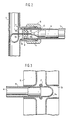
- cylindrical mounting flanges or flares 36 are fixed to or formed with the leg section 7 about the openings 35, and fixed about each of the mounting flanges 36, such as by welding, is a cylindrical mounting sleeve 8.
- the lamp assemblies, generally designated 40 in fig. 1, are mounted at their opposite ends in mounting sleeve 8 and receptacles 30 respectively.
- Each lamp assembly 40 includes an elongated ultraviolet lamp 14 and an elongated protective quartz sleeve 15 surrounding the lamp 14 to fully enclose the same.
- the right end of the protective sleeve 15, as shown in fig. 1 extends beyond the adjacent end of lamp 14 and is closed at 15a (see fig. 3).
- the left end of protective sleeve 15 extends beyond the adjacent end of lamp 14 and is formed with an opening in alignment with the opening 35.
- the left end of the protective sleeve 15 is mounted coaxially within the mounting sleeve 8 while the right end is mounted in receptacle 30 as best shown in fig. 3.
- a plurality of flexible and resilient seats, preferably "O" rings 17 are provided in the split leg section to surround the receptacles 30 and receive the protective sleeves respectively as shown in fig. 3.
- each lamp 14 has, on the left end thereof as shown, a connector 13 having contact pins (not shown) received in sockets formed in the end of the lamp.
- Lead wires 11 provided for driving the lamps respectively extend from the connectors 13 through openings 35 and vertically within the hollow passages of leg sections 3 and 7. All of the lead wires 11 for driving all of the lamps 14 of each module are located in the left-hand leg sections 3 and 7 from which they are connected to the ballast 2.
- annular seal preferably an "O" ring 9 is mounted about each protective sleeve 15 at the end of the mounting sleeve 8.
- a nut 10 is threaded onto mounting sleeve 8 and has an internal shoulder engaged with the "O" ring 9. Advancement of nut 10 along mounting sleeve 8 will deform the "O" ring radially inwardly to establish a fluid tight seal about the protective sleeve 8.
- "O" rings 9 also help to provide a resilient mount for the lamp assemblies.
- closure 12 In order to prevent entry of fluid through openings 35 and into the hollow leg section 7, each of the openings 35 is sealed closed by a closure or plug 12 made of a suitable flexible rubberlike material.
- closure 12 includes a first sealing segment 12a having a generally cylindrical shape and butted against the flanges 36 surrounding openings 35 with the peripheral surface of the sealing segment 12a continuously in sealing engagement with the inside surface of the mounting sleeve 8 as shown in fig. 2.
- closure 12 is formed with another sealing segment 12b axially spaced inwardly of segment 12a and formed by opposed frusto-conical portions defining a thin circular sealing lip in continuous sealing engagement with the inside surface of the protective sleeve 15; it being understood that the diameter of sealing segment 12b is less than that of segment 12a.
- Closure 12 also provides a flexible and resilient cushion mount for the end of the protective sleeve 15 which abuts against the sealing segment 12a while being received on sealing segment 12b as shown in fig. 2. It will thus be seen that should the protective sleeve 15 break allowing fluid to pass "O" ring 9, the fluid will be prevented from passing sealing segments 12a or 12b to enter the leg 7.
- the closures 12 are molded about a respective lead wire 11 which extends inwardly from the closure 12 to the connector 13.
- the connector 13 may be formed or located within the closure 12 itself which may be an electrical receptacle. Additionnally, other types of electrical connections to the lamps 14 may be made at or in the closure 12.
- the various parts of the module frame including split leg sections 16a, 16b may be made from suitable non-corrosive material such as stainless steel. Also, if desired, nuts 10 may be made from plastic such as DELRIN material.
- the present invention reduces the number of external lead wires required for the lamps while also placing them in a single frame leg thus allowing the other leg to be economically made and without electrical connections and seals at that leg.
- the incorporation of the ballast in the frame itself obviates the need of an external control panel to further reduce parts and cost.
- the present invention improves the mounting and sealing of the lamp assemblies while, at the same time, preventing fluid contact with the lead wires and electrical connections.
Landscapes
- Health & Medical Sciences (AREA)
- Chemical & Material Sciences (AREA)
- Organic Chemistry (AREA)
- Life Sciences & Earth Sciences (AREA)
- General Health & Medical Sciences (AREA)
- Toxicology (AREA)
- Electromagnetism (AREA)
- Physics & Mathematics (AREA)
- Veterinary Medicine (AREA)
- Public Health (AREA)
- Animal Behavior & Ethology (AREA)
- Epidemiology (AREA)
- Chemical Kinetics & Catalysis (AREA)
- Hydrology & Water Resources (AREA)
- Engineering & Computer Science (AREA)
- Environmental & Geological Engineering (AREA)
- Water Supply & Treatment (AREA)
- Physical Water Treatments (AREA)
Applications Claiming Priority (2)
| Application Number | Priority Date | Filing Date | Title |
|---|---|---|---|
| US07/243,845 US4872980A (en) | 1988-09-13 | 1988-09-13 | Fluid purification device |
| US243845 | 1988-09-13 |
Publications (2)
| Publication Number | Publication Date |
|---|---|
| EP0361579A1 true EP0361579A1 (fr) | 1990-04-04 |
| EP0361579B1 EP0361579B1 (fr) | 1993-02-10 |
Family
ID=22920361
Family Applications (1)
| Application Number | Title | Priority Date | Filing Date |
|---|---|---|---|
| EP89202305A Expired - Lifetime EP0361579B1 (fr) | 1988-09-13 | 1989-09-12 | Dispositif de purification de fluide |
Country Status (5)
| Country | Link |
|---|---|
| US (1) | US4872980A (fr) |
| EP (1) | EP0361579B1 (fr) |
| JP (3) | JP2944681B2 (fr) |
| CA (1) | CA1327877C (fr) |
| DE (1) | DE68904854T2 (fr) |
Cited By (2)
| Publication number | Priority date | Publication date | Assignee | Title |
|---|---|---|---|---|
| US5725757A (en) * | 1995-01-16 | 1998-03-10 | Otv Omnium De Traitements Et De Valorisation (Societe Anonyme) | Reactor for UV radiation for the treatment of liquids |
| DE19653083A1 (de) * | 1996-12-19 | 1998-06-25 | Wedeco Gmbh | Strömungsgünstige UV-Desinfektionsvorrichtung |
Families Citing this family (58)
| Publication number | Priority date | Publication date | Assignee | Title |
|---|---|---|---|---|
| JPH0322587U (fr) * | 1989-07-17 | 1991-03-08 | ||
| US5019256A (en) * | 1990-10-19 | 1991-05-28 | Fischer & Porter Company | Ultraviolet lamp rack assembly |
| DE4119725C2 (de) * | 1991-06-16 | 1997-09-18 | Delta Uv Gmbh | Vorrichtung zur Bestrahlung von Wasser im Freispiegelabfluß mit UV-Licht |
| DE4220088C2 (de) * | 1992-06-19 | 1997-06-05 | Delta Uv Gmbh | Vorrichtung zur UV-Bestrahlung von Wasser |
| USRE36896E (en) * | 1993-03-05 | 2000-10-03 | Trojan Technologies Inc. | Fluid treatment system and process |
| TW360619B (en) * | 1993-03-05 | 1999-06-11 | Trojan Techn Inc | A cleaning apparatus for a radiation source assembly in a fluid treatment system and a method of removal of fouling materials therefrom |
| US5539209A (en) * | 1994-10-17 | 1996-07-23 | Trojan Technologies Inc. | Method of cleaning fouling materials from a radiation module |
| US5504335A (en) * | 1994-10-17 | 1996-04-02 | Trojan Technologies, Inc. | Fluid treatment device and method |
| US5792433A (en) * | 1995-03-13 | 1998-08-11 | Photoscience Japan Corporation | Light irradiating device with easily replaceable light irradiating lamps |
| US6083387A (en) * | 1996-06-20 | 2000-07-04 | Burnham Technologies Ltd. | Apparatus for the disinfection of fluids |
| US5997812A (en) * | 1996-06-20 | 1999-12-07 | Coolant Treatment Systems, L.L.C. | Methods and apparatus for the application of combined fields to disinfect fluids |
| US5846437A (en) | 1997-01-03 | 1998-12-08 | Trojan Technologies Inc. | Increasing turbulent mixing in a UV system |
| CA2303180A1 (fr) * | 1997-09-11 | 1999-03-18 | Don Meader | Appareil servant a desactiver des micro-organismes |
| US6015229A (en) * | 1997-09-19 | 2000-01-18 | Calgon Carbon Corporation | Method and apparatus for improved mixing in fluids |
| US6144175A (en) * | 1997-11-05 | 2000-11-07 | Parra; Jorge M. | Low-voltage ballast-free energy-efficient ultraviolet material treatment and purification system and method |
| US6465971B1 (en) | 1999-06-02 | 2002-10-15 | Jorge M. Parra | Plastic “trofer” and fluorescent lighting system |
| US6411041B1 (en) * | 1999-06-02 | 2002-06-25 | Jorge M. Parra | Non-thermionic fluorescent lamps and lighting systems |
| KR100523009B1 (ko) | 1999-06-04 | 2005-10-20 | 헨리 코즐로프스키 | 유체의 자외선 광처리용 장치 |
| US6830697B1 (en) | 1999-09-03 | 2004-12-14 | Trojan Technologies Inc. | Fluid treatment system, radiation source assembly and radiation source module |
| WO2001025153A1 (fr) * | 1999-10-01 | 2001-04-12 | Trojan Technologies Inc. | Systeme de detection de rayonnement optique avec dispositif de nettoyage |
| KR20020060778A (ko) * | 1999-12-06 | 2002-07-18 | 홀던 데이비드 | 프로세스에서 적어도 하나의 유체 흐름 변수를 예측하는온라인 장치 |
| US6507028B2 (en) | 1999-12-17 | 2003-01-14 | Trojan Technologies, Inc. | Radiation source module |
| DE60038629D1 (de) | 1999-12-17 | 2008-05-29 | Trojan Techn Inc | Optisches strahlungsmessgerät |
| ATE402908T1 (de) * | 2000-06-06 | 2008-08-15 | Trojan Techn Inc | Mischvorrichtung für fluide |
| CN1481337A (zh) * | 2000-12-15 | 2004-03-10 | 特洛伊人技术公司 | 流体处理系统和用于其中的辐射源标准组件 |
| US6719491B2 (en) | 2001-08-03 | 2004-04-13 | Trojan Technologies Inc. | Fluid level control system |
| US6663318B2 (en) | 2001-08-03 | 2003-12-16 | Trojan Technologies, Inc. | Fluid level control system |
| EP1436231A2 (fr) * | 2001-09-20 | 2004-07-14 | Trojan Technologies Inc. | Systeme de traitement de fluide |
| CN1659263A (zh) | 2002-03-20 | 2005-08-24 | 特洛伊人技术公司 | 清洁剂和清洁表面的方法 |
| US7419642B2 (en) * | 2002-05-07 | 2008-09-02 | Ultravation, Inc. | Fluid disinfection apparatus |
| US20050069463A1 (en) * | 2002-05-07 | 2005-03-31 | Kurtz Mark E. | Fluid disinfection apparatus |
| EP1515915B1 (fr) * | 2002-06-19 | 2014-11-12 | Trojan Technologies Inc. | Systeme de traitement de fluide et module source de rayonnement utilise dans ce systeme |
| US6784440B2 (en) | 2002-07-26 | 2004-08-31 | Boc, Inc. | Food sanitizing cabinet |
| WO2004033375A1 (fr) * | 2002-10-09 | 2004-04-22 | Trojan Technologies Inc. | Systeme de traitement de fluide par rayonnement ultraviolet |
| US7160566B2 (en) | 2003-02-07 | 2007-01-09 | Boc, Inc. | Food surface sanitation tunnel |
| CA2559551C (fr) * | 2004-03-12 | 2012-12-04 | Trojan Technologies Inc. | Systeme de traitement de fluide |
| CN102557313A (zh) * | 2004-04-15 | 2012-07-11 | 特洛伊人技术公司 | 水处理设备以及在流体处理系统中使用的处理筒 |
| US7759651B2 (en) * | 2004-04-19 | 2010-07-20 | Trojan Technologies | Optical radiation sensor system and method for measuring radiation transmittance of a fluid |
| WO2006002521A1 (fr) | 2004-06-30 | 2006-01-12 | Trojan Technologies Inc. | Dispositif detecteur de rayonnement et systeme de traitement de fluide contenant ce dispositif |
| US7241380B2 (en) * | 2005-06-15 | 2007-07-10 | Reiling Dennis R | Ultraviolet treatment unit and septic tank system |
| CA2621301C (fr) * | 2005-08-31 | 2013-04-30 | Trojan Technologies Inc. | Lampe a rayonnement ultraviolet, module source et systeme les renfermant |
| US8679416B2 (en) | 2006-08-17 | 2014-03-25 | Trojan Technologies | Fluid treatment system |
| EP2535316B1 (fr) | 2006-11-06 | 2018-04-11 | Trojan Technologies | Système de traitement de fluide |
| AU2008338208A1 (en) | 2007-12-14 | 2009-06-25 | Trojan Technologies | Radiation source assembly and fluid treatment system |
| CN104549097B (zh) * | 2008-11-26 | 2017-04-12 | 卡尔冈碳素公司 | 在污水/循环水紫外消毒系统中混合部件的使用方法和装置 |
| EP2406018A4 (fr) | 2009-03-13 | 2013-03-06 | Trojan Techn Inc | Appareil de nettoyage, module source de rayonnement et système de traitement de fluide |
| CN102596436A (zh) | 2009-11-12 | 2012-07-18 | 特洁安科技有限公司 | 清洗设备,辐射源模块和流体处理系统 |
| WO2012037644A1 (fr) | 2010-09-10 | 2012-03-29 | Trojan Technologies | Ensemble source de rayonnement |
| CN102728293A (zh) | 2010-10-04 | 2012-10-17 | 特洁安科技有限公司 | 套筒支持器装置 |
| EP2651550B1 (fr) | 2010-12-16 | 2021-04-14 | Trojan Technologies | Module source de rayonnement et système de traitement de fluide |
| JP5765618B2 (ja) * | 2011-03-16 | 2015-08-19 | 三浦工業株式会社 | 水殺菌ランプユニット |
| CN104145122A (zh) | 2012-01-20 | 2014-11-12 | 特洁安技术公司 | 流体流量调节器和结合其的流体处理系统 |
| EP2817105B1 (fr) | 2012-02-23 | 2019-04-10 | Trojan Technologies | Système de nettoyage de source de rayonnement et module contenant celui-ci |
| EP2928622A4 (fr) | 2012-12-07 | 2016-08-24 | Trojan Techn Inc | Appareil de nettoyage |
| JP6535004B2 (ja) | 2013-08-29 | 2019-06-26 | クリスタル アイエス, インコーポレーテッドCrystal Is, Inc. | 紫外線の均一分散の液体処理の装置及び方法 |
| CN204481158U (zh) * | 2015-03-19 | 2015-07-15 | 中山市威德轻工机电制品有限公司 | 接地线分体螺母及其应用的紫外线水体杀菌器 |
| EP3081534B1 (fr) * | 2015-04-16 | 2021-03-03 | Trojan Technologies Inc. | Module de source de rayonnement et système de traitement de fluide |
| DK4244328T3 (da) | 2020-11-14 | 2025-10-13 | Mark Anthony Int Srl | Fremgangsmåder til sterilisering af fermenterede drikkevarer |
Citations (2)
| Publication number | Priority date | Publication date | Assignee | Title |
|---|---|---|---|---|
| US4367410A (en) * | 1979-07-09 | 1983-01-04 | Pure Water Systems, Inc. | Waste purification apparatus and method |
| US4482809A (en) * | 1981-11-30 | 1984-11-13 | Trojan Technologies Inc. | Ultraviolet fluid purifying device |
Family Cites Families (4)
| Publication number | Priority date | Publication date | Assignee | Title |
|---|---|---|---|---|
| US3462597A (en) * | 1966-07-29 | 1969-08-19 | Ultra Dynamics Corp | Ultraviolet fluid purifier having manually operable wiper means |
| US4255663A (en) * | 1977-03-24 | 1981-03-10 | Lewis James H | Disposable liquid sterilizer unit |
| US4400270A (en) * | 1980-04-18 | 1983-08-23 | Adco Aerospace, Inc. | Ultraviolet apparatus for disinfection and sterilization of fluids |
| US4757205A (en) * | 1986-06-10 | 1988-07-12 | Arlat Inc. | Ultraviolet water treatment apparatus |
-
1988
- 1988-09-13 US US07/243,845 patent/US4872980A/en not_active Expired - Lifetime
-
1989
- 1989-08-16 CA CA000608487A patent/CA1327877C/fr not_active Expired - Lifetime
- 1989-09-12 EP EP89202305A patent/EP0361579B1/fr not_active Expired - Lifetime
- 1989-09-12 DE DE8989202305T patent/DE68904854T2/de not_active Expired - Fee Related
- 1989-09-13 JP JP1238366A patent/JP2944681B2/ja not_active Expired - Fee Related
-
1996
- 1996-09-12 JP JP8278511A patent/JP3032474B2/ja not_active Expired - Fee Related
- 1996-09-12 JP JP8278510A patent/JP3032719B2/ja not_active Expired - Fee Related
Patent Citations (2)
| Publication number | Priority date | Publication date | Assignee | Title |
|---|---|---|---|---|
| US4367410A (en) * | 1979-07-09 | 1983-01-04 | Pure Water Systems, Inc. | Waste purification apparatus and method |
| US4482809A (en) * | 1981-11-30 | 1984-11-13 | Trojan Technologies Inc. | Ultraviolet fluid purifying device |
Cited By (3)
| Publication number | Priority date | Publication date | Assignee | Title |
|---|---|---|---|---|
| US5725757A (en) * | 1995-01-16 | 1998-03-10 | Otv Omnium De Traitements Et De Valorisation (Societe Anonyme) | Reactor for UV radiation for the treatment of liquids |
| DE19653083A1 (de) * | 1996-12-19 | 1998-06-25 | Wedeco Gmbh | Strömungsgünstige UV-Desinfektionsvorrichtung |
| DE19653083B4 (de) * | 1996-12-19 | 2005-09-08 | Wedeco Ag Water Technology | Strömungsgünstige UV-Desinfektionsvorrichtung |
Also Published As
| Publication number | Publication date |
|---|---|
| JP3032474B2 (ja) | 2000-04-17 |
| JP3032719B2 (ja) | 2000-04-17 |
| DE68904854D1 (de) | 1993-03-25 |
| US4872980A (en) | 1989-10-10 |
| JPH09103778A (ja) | 1997-04-22 |
| JP2944681B2 (ja) | 1999-09-06 |
| JPH02174989A (ja) | 1990-07-06 |
| DE68904854T2 (de) | 1993-06-17 |
| CA1327877C (fr) | 1994-03-22 |
| EP0361579B1 (fr) | 1993-02-10 |
| JPH09103779A (ja) | 1997-04-22 |
Similar Documents
| Publication | Publication Date | Title |
|---|---|---|
| EP0361579B1 (fr) | Dispositif de purification de fluide | |
| US5006244A (en) | Fluid purification device | |
| US4482809A (en) | Ultraviolet fluid purifying device | |
| US5091152A (en) | Apparatus for electrically destroying targeted organisms in fluids | |
| RU2232722C2 (ru) | Способ и устройство для обработки текучих сред ультрафиолетовым излучением и средство для передачи электрических сигналов, используемое в этом устройстве | |
| US5290439A (en) | Device for purifying a flow of liquid by means of ultraviolet radiation | |
| US5256371A (en) | Method and arrangement for disinfecting a dialysis fluid circuit | |
| CA2275633C (fr) | Dispositif de desinfection par u.v. favorisant l'ecoulement | |
| US7390225B2 (en) | Radiation lamp and radiation source module incorporating same | |
| US7095167B2 (en) | Germicidal low pressure mercury vapor discharge lamp with amalgam location permitting high output | |
| JP2003501242A5 (fr) | ||
| JP4567184B2 (ja) | 衛生設備を貫流する水を滅菌する装置 | |
| EP1949402B1 (fr) | Lampe et source de rayonnement ainsi que système de désinfection de l'eau comprenant une telle lampe | |
| WO1999038807A8 (fr) | Systeme d'epuration d'eau | |
| BR9402044A (pt) | Válvula de luz | |
| WO1997033631A1 (fr) | Systeme de sterilisation par les uv pour fluides | |
| KR960005743A (ko) | 카드뮴램프 발광장치 | |
| ES2109059T3 (es) | Canalizacion electrica prefabricada. | |
| GB2185205A (en) | Method and welding electrode for making a welding seam | |
| BR7900580U (pt) | Reator adaptador para lâmpada fluorescente tubular |
Legal Events
| Date | Code | Title | Description |
|---|---|---|---|
| PUAI | Public reference made under article 153(3) epc to a published international application that has entered the european phase |
Free format text: ORIGINAL CODE: 0009012 |
|
| AK | Designated contracting states |
Kind code of ref document: A1 Designated state(s): BE CH DE FR GB IT LI NL |
|
| 17P | Request for examination filed |
Effective date: 19900820 |
|
| 17Q | First examination report despatched |
Effective date: 19910130 |
|
| GRAA | (expected) grant |
Free format text: ORIGINAL CODE: 0009210 |
|
| AK | Designated contracting states |
Kind code of ref document: B1 Designated state(s): BE CH DE FR GB IT LI NL |
|
| REF | Corresponds to: |
Ref document number: 68904854 Country of ref document: DE Date of ref document: 19930325 |
|
| ET | Fr: translation filed | ||
| ITF | It: translation for a ep patent filed | ||
| K2C3 | Correction of patent specification (complete document) published |
Effective date: 19930210 |
|
| PLBE | No opposition filed within time limit |
Free format text: ORIGINAL CODE: 0009261 |
|
| STAA | Information on the status of an ep patent application or granted ep patent |
Free format text: STATUS: NO OPPOSITION FILED WITHIN TIME LIMIT |
|
| 26N | No opposition filed | ||
| PGFP | Annual fee paid to national office [announced via postgrant information from national office to epo] |
Ref country code: NL Payment date: 20010927 Year of fee payment: 13 |
|
| PGFP | Annual fee paid to national office [announced via postgrant information from national office to epo] |
Ref country code: CH Payment date: 20011001 Year of fee payment: 13 |
|
| PGFP | Annual fee paid to national office [announced via postgrant information from national office to epo] |
Ref country code: BE Payment date: 20011119 Year of fee payment: 13 |
|
| REG | Reference to a national code |
Ref country code: GB Ref legal event code: IF02 |
|
| PG25 | Lapsed in a contracting state [announced via postgrant information from national office to epo] |
Ref country code: LI Free format text: LAPSE BECAUSE OF NON-PAYMENT OF DUE FEES Effective date: 20020930 Ref country code: BE Free format text: LAPSE BECAUSE OF NON-PAYMENT OF DUE FEES Effective date: 20020930 Ref country code: CH Free format text: LAPSE BECAUSE OF NON-PAYMENT OF DUE FEES Effective date: 20020930 |
|
| BERE | Be: lapsed |
Owner name: *TROJAN TECHNOLOGIES INC. Effective date: 20020930 |
|
| PG25 | Lapsed in a contracting state [announced via postgrant information from national office to epo] |
Ref country code: NL Free format text: LAPSE BECAUSE OF NON-PAYMENT OF DUE FEES Effective date: 20030401 |
|
| REG | Reference to a national code |
Ref country code: CH Ref legal event code: PL |
|
| PGFP | Annual fee paid to national office [announced via postgrant information from national office to epo] |
Ref country code: DE Payment date: 20070913 Year of fee payment: 19 |
|
| PGFP | Annual fee paid to national office [announced via postgrant information from national office to epo] |
Ref country code: GB Payment date: 20070912 Year of fee payment: 19 |
|
| PGFP | Annual fee paid to national office [announced via postgrant information from national office to epo] |
Ref country code: FR Payment date: 20070925 Year of fee payment: 19 |
|
| PGFP | Annual fee paid to national office [announced via postgrant information from national office to epo] |
Ref country code: IT Payment date: 20080930 Year of fee payment: 20 |
|
| GBPC | Gb: european patent ceased through non-payment of renewal fee |
Effective date: 20080912 |
|
| REG | Reference to a national code |
Ref country code: FR Ref legal event code: ST Effective date: 20090529 |
|
| PG25 | Lapsed in a contracting state [announced via postgrant information from national office to epo] |
Ref country code: DE Free format text: LAPSE BECAUSE OF NON-PAYMENT OF DUE FEES Effective date: 20090401 |
|
| PG25 | Lapsed in a contracting state [announced via postgrant information from national office to epo] |
Ref country code: FR Free format text: LAPSE BECAUSE OF NON-PAYMENT OF DUE FEES Effective date: 20080930 |
|
| PG25 | Lapsed in a contracting state [announced via postgrant information from national office to epo] |
Ref country code: GB Free format text: LAPSE BECAUSE OF NON-PAYMENT OF DUE FEES Effective date: 20080912 |