EP0361579B1 - Flüssigkeitsreinigungsanlage - Google Patents
Flüssigkeitsreinigungsanlage Download PDFInfo
- Publication number
- EP0361579B1 EP0361579B1 EP89202305A EP89202305A EP0361579B1 EP 0361579 B1 EP0361579 B1 EP 0361579B1 EP 89202305 A EP89202305 A EP 89202305A EP 89202305 A EP89202305 A EP 89202305A EP 0361579 B1 EP0361579 B1 EP 0361579B1
- Authority
- EP
- European Patent Office
- Prior art keywords
- leg
- lamp
- legs
- protective
- protective sleeve
- Prior art date
- Legal status (The legal status is an assumption and is not a legal conclusion. Google has not performed a legal analysis and makes no representation as to the accuracy of the status listed.)
- Expired - Lifetime
Links
Images

Classifications
-
- A—HUMAN NECESSITIES
- A61—MEDICAL OR VETERINARY SCIENCE; HYGIENE
- A61L—METHODS OR APPARATUS FOR STERILISING MATERIALS OR OBJECTS IN GENERAL; DISINFECTION, STERILISATION OR DEODORISATION OF AIR; CHEMICAL ASPECTS OF BANDAGES, DRESSINGS, ABSORBENT PADS OR SURGICAL ARTICLES; MATERIALS FOR BANDAGES, DRESSINGS, ABSORBENT PADS OR SURGICAL ARTICLES
- A61L2/00—Disinfection or sterilisation of materials or objects, in general; Accessories therefor
- A61L2/02—Disinfection or sterilisation of materials or objects, in general; Accessories therefor using physical processes
- A61L2/08—Radiation
- A61L2/10—Ultraviolet [UV] radiation
-
- B—PERFORMING OPERATIONS; TRANSPORTING
- B01—PHYSICAL OR CHEMICAL PROCESSES OR APPARATUS IN GENERAL
- B01J—CHEMICAL OR PHYSICAL PROCESSES, e.g. CATALYSIS OR COLLOID CHEMISTRY; THEIR RELEVANT APPARATUS
- B01J19/00—Chemical, physical or physico-chemical processes in general; Their relevant apparatus
- B01J19/08—Processes employing the direct application of electric or wave energy, or particle radiation; Apparatus therefor
- B01J19/12—Processes employing the direct application of electric or wave energy, or particle radiation; Apparatus therefor employing electromagnetic waves
- B01J19/122—Incoherent waves
- B01J19/123—Ultraviolet light
-
- C—CHEMISTRY; METALLURGY
- C02—TREATMENT OF WATER, WASTE WATER, SEWAGE, OR SLUDGE
- C02F—TREATMENT OF WATER, WASTE WATER, SEWAGE, OR SLUDGE
- C02F1/00—Treatment of water, waste water, or sewage
- C02F1/30—Treatment of water, waste water, or sewage by irradiation
- C02F1/32—Treatment of water, waste water, or sewage by irradiation with ultraviolet light
- C02F1/325—Irradiation devices or lamp constructions
-
- C—CHEMISTRY; METALLURGY
- C02—TREATMENT OF WATER, WASTE WATER, SEWAGE, OR SLUDGE
- C02F—TREATMENT OF WATER, WASTE WATER, SEWAGE, OR SLUDGE
- C02F2201/00—Apparatus for treatment of water, waste water or sewage
- C02F2201/32—Details relating to UV-irradiation devices
- C02F2201/322—Lamp arrangement
- C02F2201/3227—Units with two or more lamps
Definitions
- the present invention relates to an ultraviolet lamp fluid purifying device adapted to be placed in a fluid to be purified, the device comprising in combination, a support frame including a pair of opposed legs which are spaced apart from one another, a cross piece extending between said legs and at least one lamp assembly extending between and supported by said legs, said lamp having one end located towards one of said legs and an opposite end located towards the other leg, and one or more electrical lead wires connected to said lamp.
- This device for the sterilization of fluids, such as waste water, through ultraviolet light rays which are capable of killing or destroying unwanted microorganisms in fluids includes a plurality of lamp modules.
- ultraviolet lamps to be immersed in a fluid to be purified are mounted to the legs of a frame by their surrounding protective sleeves whose opposite ends are open and mounted and sealed in sockets spaced along the legs.
- the lamps are powered through lead wires extending from an external control panel and received in both legs of the frame which are hollow for this purpose.
- the lead wires are connected to opposite ends of the lamps through contacts in the sockets; there being a separate pair of lead wires connected to each lamp at the opposite ends thereof respectively.
- the voltage and amperage of the lamps are controlled at a control panel located externally of the lamp modules.
- An object of the present invention is to simplify fluid purification devices of the above mentioned type.
- Said electrical means are preferably ballast means.
- Another object is to provide a fluid purification device which simplifies and improves the mounting and sealing of the lamp assemblies while simplifying and reducing the electrical connections for the lamps.
- a preferred embodiment of the device of the present invention includes a frame having spaced legs in which a plurality of lamp assemblies are mounted; each assembly including an elongated ultraviolet lamp and a surrounding protective sleeve closed at one end.
- One of the legs has a hollow passage receiving lead wires for powering all of the lamps and the other leg is free of any lead wires.
- the lead wires are connected to one of the ends of the lamps through openings spaced along the hollow leg.
- One of the ends of the protective sleeves is open and mounted in an improved manner to the hollow legs in alignment with the leg openings which are sealed by closures containing electrical conductors interconnecting the lead wires and the lamps.
- the inner and outer surfaces of the protective sleeves at said one end thereof are sealed to prevent fluid contact with the electrical connections.
- the other ends of the protective sleeves are closed and mounted in resilient seats carried in receptacles formed in the other frame leg.
- the latter is formed by two plates fixed together with registering recesses forming the receptacles.
- An electrical ballast for at least controlling the amperage at the lamps is incorporated in the frame of the device.
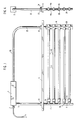
- the device in its preferred form, includes an inverted U-shape frame including opposite legs interconnected at the top by a cross piece 20 which preferably includes a ballast 2 connected to a power cord 4 by a strain relief 1. Ballast 2 controls the voltage and/or amperage through ultraviolet lamps 14 mounted to and between the frame legs as will be described below.
- Ballast 2 also functions to limit the amperage through the lamps.
- the frame leg on the left as shown in fig. 1 includes upper and lower hollow tubular sections 3 and 7 joined, such as by butt welding, to each other in axial alignment, with the lower end of section 7 being closed.
- the frame leg shown on the right in fig. 1 is also formed in two joined sections including an upper section 22 which may be integral with cross piece 20 and a lower section 16 formed by two plates 16a and 16b. The latter are welded together at flat web portions 26 and are formed with registering semi-cylindrical recesses 28 providing cylindrical receptacles 30 extending tranversely between the webs for receiving the lamp assemblies as will be described below.
- Mounted to and between intermediate portions of the frame legs is an inverted generally U-shaped channel 6 having collars 32 fixed thereto with set screws 34 for securing channel 6 in desired position. Channel 6 serves to reinforce the frame and also as a barrier to the ultraviolet light.
- Lower leg section 7 has a plurality of openings 35 formed along its length at spaced locations.
- the lamp assemblies are mounted at one of their ends to leg 7 in alignment with openings 35 respectively.
- cylindrical mounting flanges or flares 36 are fixed to or formed with the leg section 7 about the openings 35, and fixed about each of the mounting flanges 36, such as by welding, is a cylindrical mounting sleeve 8.
- the lamp assemblies, generally designated 40 in fig. 1, are mounted at their opposite ends in mounting sleeve 8 and receptacles 30 respectively.
- Each lamp assembly 40 includes an elongated ultraviolet lamp 14 and an elongated protective quartz sleeve 15 surrounding the lamp 14 to fully enclose the same.
- the right end of the protective sleeve 15, as shown in fig. 1 extends beyond the adjacent end of lamp 14 and is closed at 15a (see fig. 3).
- the left end of protective sleeve 15 extends beyond the adjacent end of lamp 14 and is formed with an opening in alignment with the opening 35.
- the left end of the protective sleeve 15 is mounted coaxially within the mounting sleeve 8 while the right end is mounted in receptacle 30 as best shown in fig. 3.
- a plurality of flexible and resilient seats, preferably "O" rings 17 are provided in the split leg section to surround the receptacles 30 and receive the protective sleeves respectively as shown in fig. 3.
- each lamp 14 has, on the left end thereof as shown, a connector 13 having contact pins (not shown) received in sockets formed in the end of the lamp.
- Lead wires 11 provided for driving the lamps respectively extend from the connectors 13 through openings 35 and vertically within the hollow passages of leg sections 3 and 7. All of the lead wires 11 for driving all of the lamps 14 of each module are located in the left-hand leg sections 3 and 7 from which they are connected to the ballast 2.
- annular seal preferably an "O" ring 9 is mounted about each protective sleeve 15 at the end of the mounting sleeve 8.
- a nut 10 is threaded onto mounting sleeve 8 and has an internal shoulder engaged with the "O" ring 9. Advancement of nut 10 along mounting sleeve 8 will deform the "O" ring radially inwardly to establish a fluid tight seal about the protective sleeve 8.
- "O" rings 9 also help to provide a resilient mount for the lamp assemblies.
- closure 12 In order to prevent entry of fluid through openings 35 and into the hollow leg section 7, each of the openings 35 is sealed closed by a closure or plug 12 made of a suitable flexible rubberlike material.
- closure 12 includes a first sealing segment 12a having a generally cylindrical shape and butted against the flanges 36 surrounding openings 35 with the peripheral surface of the sealing segment 12a continuously in sealing engagement with the inside surface of the mounting sleeve 8 as shown in fig. 2.
- closure 12 is formed with another sealing segment 12b axially spaced inwardly of segment 12a and formed by opposed frusto-conical portions defining a thin circular sealing lip in continuous sealing engagement with the inside surface of the protective sleeve 15; it being understood that the diameter of sealing segment 12b is less than that of segment 12a.
- Closure 12 also provides a flexible and resilient cushion mount for the end of the protective sleeve 15 which abuts against the sealing segment 12a while being received on sealing segment 12b as shown in fig. 2. It will thus be seen that should the protective sleeve 15 break allowing fluid to pass "O" ring 9, the fluid will be prevented from passing sealing segments 12a or 12b to enter the leg 7.
- the closures 12 are molded about a respective lead wire 11 which extends inwardly from the closure 12 to the connector 13.
- the connector 13 may be formed or located within the closure 12 itself which may be an electrical receptacle. Additionnally, other types of electrical connections to the lamps 14 may be made at or in the closure 12.
- the various parts of the module frame including split leg sections 16a, 16b may be made from suitable non-corrosive material such as stainless steel. Also, if desired, nuts 10 may be made from plastic such as DELRINTM material.
- the present invention reduces the number of external lead wires required for the lamps while also placing them in a single frame leg thus allowing the other leg to be economically made and without electrical connections and seals at that leg.
- the incorporation of the ballast in the frame itself obviates the need of an external control panel to further reduce parts and cost.
- the present invention improves the mounting and sealing of the lamp assemblies while, at the same time, preventing fluid contact with the lead wires and electrical connections.
Landscapes
- Health & Medical Sciences (AREA)
- Chemical & Material Sciences (AREA)
- Organic Chemistry (AREA)
- Life Sciences & Earth Sciences (AREA)
- General Health & Medical Sciences (AREA)
- Toxicology (AREA)
- Electromagnetism (AREA)
- Physics & Mathematics (AREA)
- Veterinary Medicine (AREA)
- Public Health (AREA)
- Animal Behavior & Ethology (AREA)
- Epidemiology (AREA)
- Chemical Kinetics & Catalysis (AREA)
- Hydrology & Water Resources (AREA)
- Engineering & Computer Science (AREA)
- Environmental & Geological Engineering (AREA)
- Water Supply & Treatment (AREA)
- Physical Water Treatments (AREA)
Claims (10)
- UV-Lampen-Flüssigkeitsreinigungsvorrichtung zum Einsetzen in eine zu reinigende Flüssigkeit, bestehend aus der Kombination aus einem Tragrahmen mit einem Paar gegenüberliegender Schenkel (7, 16), die voneinander abgesestzt sind; einem zwischen den Schenkeln und mindestens einer zwischen den Schenkeln eingesetzten und auf diesen aufgelagerten Lampe (14) angeordneten Querelement (20), wobei die Lampe mit einem Ende gegen einen der Schenkel und mit gegenüberliegenden Ende gegen den anderen Schenkel anliegt; und einer oder mehreren elektrischen Zuleitungen, die mit der Lampe (14) verbunden ist/sind,
dadurch gekennzeichnet,
daß eine elektrische oder elektronische Vorrichtung (2) zur Regelung der ordnungsgemäßen Arbeitsweise der Lampe bei deren Aktivierung oder in deren aktiviertem Zustand und zur Veränderung der Spannung bzw. der Stromstärke der Lampe während des Betriebs auf dem Rahmen montiert oder in den Rahmen eingebaut ist. - Vorrichtung nach Anspruch 1, dadurch gekennzeichnet, daß es sich den elektrischen Vorrichtungen um Vorschaltgeräte (2) zur Regelung der durch die Lampen gehenden Spannung bzw. Stromstärke handelt.
- Vorrichtung nach Anspruch 1 oder 2, dadurch gekennzeichnet, daß der Rahmen ein Querelement (20) umfaßt, das sich zwischen den Schenkeln (7, 3; 16, 22) erstreckt, und daß das Vorschaltgerät (2) auf dem Querelement montiert oder in dieses eingebaut ist.
- Vorrichtung nach irgendeinem der vorstehenden Patentansprüche, dadurch gekennzeichnet, daß die Zuleitungen (11) entlang einem der Schenkel verlaufen.
- Vorrichtung nach irgendeinem der vorstehenden Patentansprüche, dadurch gekennzeichnet, daß mindestens einer der Schenkel (7) mit einem in Längsrichtung verlaufenden Durchgang zur Aufnahme der Zuleitung(en) versehen ist.
- Vorrichtung nach irgendeinem der vorstehenden Patentansprüche, gekennzeichnet durch mindestens eines der folgenden Merkmale:a) daß eine Schutzhülse (15) die Lampe umgibt;b) daß eine Vielzahl von zweiten Abdichtungen vorgesehen ist, die jeweils in Öffnungen der Schutzhülsen außerhalb der Lampen eingepaßt sind, um die Öffnungen in den Schutzhülsen zu verschließen;c) daß eine Vielzahl von Einbauhülsen (8) vorgesehen ist, die um die Öffnungen in einem Schenkel herum befestigt sind und zur Aufnahme von Abschnitten der neben dem Schenkel angeordneten Schutzhülsen dienen, wobei jede Einbauhülse um eine Außenfläche einer zugehörigen Schutzhülse dicht anliegt;d) daß zu jeder Einbauhülse (8) eine Vorrichtung mit einem O-Ring zur Abdichtung der Einbauhülse auf der enstprechenden Schutzhülse gehört, wobei möglichst die Einbauhülsen die ersten Abdichtungen dicht anliegend aufnehmen;e)daß eine Vielzahl von Muttern vorgesehen ist, die um die Einbauhülsen herum gelegt sind, um die O-ringe in dichtenden Eingriff mit den Schutzhülsen (15) zu bringen;f) daß der andere Schenkel (16) des Rahmens zwei in Längsrichtung geteilte Blechabschnitte (16a; 16b) mit sich überdeckenden Aussparrungen (28) zur Ausbildung von Fassungen (30) zur Aufnahme der gegenüberliegenden Lampenenden umfaßt;g) daß der andere Schenkel (16) des Rahmens zwei in Längsrichtung geteilte Blechabschnitte (16a; 16b) mit sich überdeckenden Aussparungen (28) zur Ausbildung von Fassungen (30) zur Aufnahme der gegenüberliegenden geschlossenen Enden der Schutzhülsen (15) umfaßt, wobei bevorzugt eine Vielzahl von ringförmigen elastichen Sitzen an voneinander entlang den geteilten Blechabschnitten abgesetzten Stellen vorgesehen ist, um die gegenüberliegenden geschlossenen Ende der Schutzhülsen aufzunehmen;h) daß elektrische Verbinder (13) als fester Bestandteil der Zuleitungen (11) ausgebildet sind;i) daß die ersten Dichtungen um die Zuleitungen herum angegossen sind;j) daß die Zweiten Dichtungen einen festen Bestandteil der ersten Dichtungen bilden;k) daß eine Vielzahl von die Lampen umgebenden und umschließenden Schutzhülsen vorgesehen ist, deren erste Ende dicht schließend um die ersten Dichtungen gelegt sind und deren gegenüberliegende geschlossene Enden in den anderen Schenkel eingesetzt sind;l) daß die Vorrichtung die folgenden Kombinationsmerkmale umfaßt: einen Rahmen mit einem Paar seitlich voneinander abgesetzter Schenkel (7, 16); mindestens eine zwischen den Schenkeln eingesetzte und auf diesen aufgelagerte Lampenanordung mit einer Lampe (14) und einer die Lampe auf die volle Länge umgebenden Schutzhülse (15), wobei einer der Schenkel (7) mit einem sich in Längsrichtung erstreckenden Durchgang versehen ist; eine oder mehrere elektrische Zuleitung(en) (11) im Durchgang zum Anschluß an die jeweilige Lampe, wobei der eine Schenkel (7) desweiteren eine Öffnung (35) besitzt, die entlang der Schenkellänge mit der Lampenanordnung allgemein fluchtend abgesetzt ist und mit dem Durchgang in Verbindung steht; einen die Öffnung abdichtenden und die Zuleitungen umschließenden Verschluß; und elektrische Verbinder (13) zur Verbindung der Zuleitung(en) (11) und der Lampe 14, wobei die Schutzhülse ein offenes Ende umfaßt, das um den Verschluß herum aufgepaßt ist, und ein gegenüberliegendes Ende auf dem anderen Schenkel (16) des Rahmens aufgelagert ist und um die Lampe herum dicht anliegt;m) daß desweiteren eine Einbauhülse vorgesehen ist, die an dem einem Schenkel um die Öffnung herum befestigt ist und gleichzeitig zur Aufnahme des Verschlusses und der Schutzhülse dient, und eine ringförmige Abdichtung einen dichtenden Abschluß zwischen der Einbauhülse und der Schutzhülse bildet, wobei die Schutzhülse bevorzugt mit dem Verschluß in Eingriff gelangt und durch diesen abgedichtet wird und wobei der Verschluß bevorzugt einen ersten rinförmigen Abschnitt umfaßt, der dicht schließend gegen eine Innenfläche der Einbauhülse anliegt, und einen zweiten ringförmigen Abschnitt aufweist, der gegen eine Innenfläche der Schutzhülse außerhalb der Lampe in dichtenden Eingriff gelangt; undn) daß ein weiteres Ende einer Schutzhülse geschlossen ist und auf dem anderen Schenkel aufliegt.
- Vorrichtung nach irgendeinem der vorstehenden Patentansprüche, gekennzeichnet durch eine Kombination der folgenden Merkmale: einen Rahmen mit einem Paar seitlich voneinander abgesetzter, gegenüberliegender Schenkel, wobei einer der Schenkel mit einem in Längsrichtung verlaufenden Durchgang versehen ist; eine Vielzahl von zwischen den Schenkeln eingesetzten und auf ihnen aufgelagerten Wasserreinigungslampenanordnungen, wobei jede Lampenanordnung mit einem Ende dem einen Schenkel und mit einem gegenüberliegenden Ende dem anderen Schenkel zugewandt ist; eine Vielzahl von elektrischen Zuleitungen im Durchgang des einen Endes, wobei der Schenkel (7) mit einer Vielzahl von entlang dem Schenkel abgestzten Öffnungen (35) versehen ist; eine Vielzahl von die Zuleitungen umgebenden und die Öffnungen zum Schutz vor einem Eindringen der Flüssigkeit abschließenden Abdichtungen; und elektrische Verbinder zur Verbindung der Zuleitungen mit den Lampenanordnungen, wobei die Verbinder abgedichtet sind, um im Betrieb jeden Kontakt mit der die Lampenanordnungen umgebenden Flüssigkeit zu verhindern, und wobei sich keinerlei Zuleitungen am anderen Schenkel befinden.
- Vorrichtung nach irgendeinem der vorstehenden Patentansprüche, dadurch gekennzeichnet, daß zu den Lampenanordnungen eine Vielzahl von Lampen (14) und die Lampen umgebenden und dicht umschließenden Schutzhülsen (15) gehören, wobei die Schutzhülsen an einem Ende neben den Öffnungen in dem einem Schenkel mit Öffnungen versehen und mit gegenüberliegenden geschlossenen Enden im anderen Schenkel aufgelagert sind, und wobei ein Ende der Schutzhülsen mit ersten Dichtungen in einen dicht anliegenden Eingriff gebracht wird, um die Öffnungen in den Schutzhülsen zu verschließen.
- Vorrichtung nach irgendeinen der vorstehenden Patentansprüche, gekennzeichnet durch eine Kombination der folgenden Merkmale: einen Rahmen mit einem Paar seitlich voneinander abgesetzter, gegenüberliegender Schenkel, wobei einer der Schenkel (7) mit einem in Längsrichtung verlaufenden Durchgang versehen ist; eine zwischen den Schenkeln eingesetzte und auf ihnen aufgelagerte Wasserreinigungslampe (14), die mit einem Ende dem einen Schenkel (7) und mit einem gegenüberliegenden Ende dem anderen Schenkel (16) zugewandt ist; mindestens eine elektrische Zuleitung, die im Durchgang des Schenkels angeordnet und mit der Lampe am anderen Ende verbunden ist, wobei der Schenkel (7) eine Öffnung (35) aufweist, um die Zuleitung mit der Lampe und einer die Lampe umgebenden Schutzhülse zu verbinden, wobei die Schutzhülse ein offenes Ende und eine Dichtung umfaßt, um das offene Ende zum Schutz vor dem Eindringen der Flüssigkeit zu verschließen; und eine Vorrichtung, um das offene Ende der Schutzhülse auf dem einen Schenkel anzubringen, wobei die Schutzhülse dem offenen Ende gegenüberliegend ein geschlossenes Ende aufweist, das am anderen Schenkel befestigt wird, und wobei am anderen Schenkel keinerlei Zuleitungen vorgesehen sind.
- Vorrichtung nach irgendeinem der vorstehenden Patentansprüche, gekennzeichnet durch eine Kombination der folgenden Merkmale: einen Rahmen mit einem Paar seitlich voneinander abgesetzter Schenkel; eine zwischen den Schenkeln eingesetzte und auf diese an einer entlang der Schenkel gelegenen Stelle aufgelagerte Lampenanordnung, wobei die Lampenanordnung eine längliche Lampe und eine diese umschließende Schutzhülse umfaßt, wobei einer der Schenkel (16) ein Paar länglicher Blechabschnitte (16a; 16b) aufweist, die miteinander verbunden und mit in Querichtung verlaufenden Aussparungen (28) versehen sind, die einander zur Ausbildung einer Fassung entlang dem einen Schenkel zur Aufnahme eines der Enden der Schutzhülse überdecken; und mit dem anderen Schenkel (7) verbundene Vorrichtungen, um die Lampe mit Strom zu versorgen.
Applications Claiming Priority (2)
| Application Number | Priority Date | Filing Date | Title |
|---|---|---|---|
| US07/243,845 US4872980A (en) | 1988-09-13 | 1988-09-13 | Fluid purification device |
| US243845 | 1988-09-13 |
Publications (2)
| Publication Number | Publication Date |
|---|---|
| EP0361579A1 EP0361579A1 (de) | 1990-04-04 |
| EP0361579B1 true EP0361579B1 (de) | 1993-02-10 |
Family
ID=22920361
Family Applications (1)
| Application Number | Title | Priority Date | Filing Date |
|---|---|---|---|
| EP89202305A Expired - Lifetime EP0361579B1 (de) | 1988-09-13 | 1989-09-12 | Flüssigkeitsreinigungsanlage |
Country Status (5)
| Country | Link |
|---|---|
| US (1) | US4872980A (de) |
| EP (1) | EP0361579B1 (de) |
| JP (3) | JP2944681B2 (de) |
| CA (1) | CA1327877C (de) |
| DE (1) | DE68904854T2 (de) |
Families Citing this family (60)
| Publication number | Priority date | Publication date | Assignee | Title |
|---|---|---|---|---|
| JPH0322587U (de) * | 1989-07-17 | 1991-03-08 | ||
| US5019256A (en) * | 1990-10-19 | 1991-05-28 | Fischer & Porter Company | Ultraviolet lamp rack assembly |
| DE4119725C2 (de) * | 1991-06-16 | 1997-09-18 | Delta Uv Gmbh | Vorrichtung zur Bestrahlung von Wasser im Freispiegelabfluß mit UV-Licht |
| DE4220088C2 (de) * | 1992-06-19 | 1997-06-05 | Delta Uv Gmbh | Vorrichtung zur UV-Bestrahlung von Wasser |
| USRE36896E (en) * | 1993-03-05 | 2000-10-03 | Trojan Technologies Inc. | Fluid treatment system and process |
| TW360619B (en) * | 1993-03-05 | 1999-06-11 | Trojan Techn Inc | A cleaning apparatus for a radiation source assembly in a fluid treatment system and a method of removal of fouling materials therefrom |
| US5539209A (en) * | 1994-10-17 | 1996-07-23 | Trojan Technologies Inc. | Method of cleaning fouling materials from a radiation module |
| US5504335A (en) * | 1994-10-17 | 1996-04-02 | Trojan Technologies, Inc. | Fluid treatment device and method |
| FR2729382B1 (fr) * | 1995-01-16 | 1997-03-28 | Omnium Traitement Valorisa | Reacteur d'irradiation uv pour le traitement de liquides |
| US5792433A (en) * | 1995-03-13 | 1998-08-11 | Photoscience Japan Corporation | Light irradiating device with easily replaceable light irradiating lamps |
| US6083387A (en) * | 1996-06-20 | 2000-07-04 | Burnham Technologies Ltd. | Apparatus for the disinfection of fluids |
| US5997812A (en) * | 1996-06-20 | 1999-12-07 | Coolant Treatment Systems, L.L.C. | Methods and apparatus for the application of combined fields to disinfect fluids |
| DE19653083B4 (de) * | 1996-12-19 | 2005-09-08 | Wedeco Ag Water Technology | Strömungsgünstige UV-Desinfektionsvorrichtung |
| US5846437A (en) | 1997-01-03 | 1998-12-08 | Trojan Technologies Inc. | Increasing turbulent mixing in a UV system |
| CA2303180A1 (en) * | 1997-09-11 | 1999-03-18 | Don Meader | Apparatus for deactivating microorganisms |
| US6015229A (en) * | 1997-09-19 | 2000-01-18 | Calgon Carbon Corporation | Method and apparatus for improved mixing in fluids |
| US6144175A (en) * | 1997-11-05 | 2000-11-07 | Parra; Jorge M. | Low-voltage ballast-free energy-efficient ultraviolet material treatment and purification system and method |
| US6465971B1 (en) | 1999-06-02 | 2002-10-15 | Jorge M. Parra | Plastic “trofer” and fluorescent lighting system |
| US6411041B1 (en) * | 1999-06-02 | 2002-06-25 | Jorge M. Parra | Non-thermionic fluorescent lamps and lighting systems |
| KR100523009B1 (ko) | 1999-06-04 | 2005-10-20 | 헨리 코즐로프스키 | 유체의 자외선 광처리용 장치 |
| US6830697B1 (en) | 1999-09-03 | 2004-12-14 | Trojan Technologies Inc. | Fluid treatment system, radiation source assembly and radiation source module |
| WO2001025153A1 (en) * | 1999-10-01 | 2001-04-12 | Trojan Technologies Inc. | Optical radiation sensor system with cleaning device |
| KR20020060778A (ko) * | 1999-12-06 | 2002-07-18 | 홀던 데이비드 | 프로세스에서 적어도 하나의 유체 흐름 변수를 예측하는온라인 장치 |
| US6507028B2 (en) | 1999-12-17 | 2003-01-14 | Trojan Technologies, Inc. | Radiation source module |
| DE60038629D1 (de) | 1999-12-17 | 2008-05-29 | Trojan Techn Inc | Optisches strahlungsmessgerät |
| ATE402908T1 (de) * | 2000-06-06 | 2008-08-15 | Trojan Techn Inc | Mischvorrichtung für fluide |
| CN1481337A (zh) * | 2000-12-15 | 2004-03-10 | 特洛伊人技术公司 | 流体处理系统和用于其中的辐射源标准组件 |
| US6719491B2 (en) | 2001-08-03 | 2004-04-13 | Trojan Technologies Inc. | Fluid level control system |
| US6663318B2 (en) | 2001-08-03 | 2003-12-16 | Trojan Technologies, Inc. | Fluid level control system |
| EP1436231A2 (de) * | 2001-09-20 | 2004-07-14 | Trojan Technologies Inc. | Fluidbehandlungssystem |
| CN1659263A (zh) | 2002-03-20 | 2005-08-24 | 特洛伊人技术公司 | 清洁剂和清洁表面的方法 |
| US7419642B2 (en) * | 2002-05-07 | 2008-09-02 | Ultravation, Inc. | Fluid disinfection apparatus |
| US20050069463A1 (en) * | 2002-05-07 | 2005-03-31 | Kurtz Mark E. | Fluid disinfection apparatus |
| EP1515915B1 (de) * | 2002-06-19 | 2014-11-12 | Trojan Technologies Inc. | Anlage zur behandlung von flüssigkeiten und darin verwendetes strahlungsquellemodul |
| US6784440B2 (en) | 2002-07-26 | 2004-08-31 | Boc, Inc. | Food sanitizing cabinet |
| WO2004033375A1 (en) * | 2002-10-09 | 2004-04-22 | Trojan Technologies Inc. | Ultraviolet fluid treatment system |
| US7160566B2 (en) | 2003-02-07 | 2007-01-09 | Boc, Inc. | Food surface sanitation tunnel |
| CA2559551C (en) * | 2004-03-12 | 2012-12-04 | Trojan Technologies Inc. | Fluid treatment system |
| CN102557313A (zh) * | 2004-04-15 | 2012-07-11 | 特洛伊人技术公司 | 水处理设备以及在流体处理系统中使用的处理筒 |
| US7759651B2 (en) * | 2004-04-19 | 2010-07-20 | Trojan Technologies | Optical radiation sensor system and method for measuring radiation transmittance of a fluid |
| WO2006002521A1 (en) | 2004-06-30 | 2006-01-12 | Trojan Technologies Inc. | Radiation sensor device and fluid treatment system containing same |
| US7241380B2 (en) * | 2005-06-15 | 2007-07-10 | Reiling Dennis R | Ultraviolet treatment unit and septic tank system |
| CA2621301C (en) * | 2005-08-31 | 2013-04-30 | Trojan Technologies Inc. | Ultraviolet radiation lamp and source module and treatment system containing same |
| US8679416B2 (en) | 2006-08-17 | 2014-03-25 | Trojan Technologies | Fluid treatment system |
| EP2535316B1 (de) | 2006-11-06 | 2018-04-11 | Trojan Technologies | Flüssigkeitsaufbereitungssystem |
| AU2008338208A1 (en) | 2007-12-14 | 2009-06-25 | Trojan Technologies | Radiation source assembly and fluid treatment system |
| CN104549097B (zh) * | 2008-11-26 | 2017-04-12 | 卡尔冈碳素公司 | 在污水/循环水紫外消毒系统中混合部件的使用方法和装置 |
| EP2406018A4 (de) | 2009-03-13 | 2013-03-06 | Trojan Techn Inc | Reinigungsgerät, strahlungsquellenmodul und flüssigkeitsbehandlungssystem |
| CN102596436A (zh) | 2009-11-12 | 2012-07-18 | 特洁安科技有限公司 | 清洗设备,辐射源模块和流体处理系统 |
| WO2012037644A1 (en) | 2010-09-10 | 2012-03-29 | Trojan Technologies | Radiation source assembly |
| CN102728293A (zh) | 2010-10-04 | 2012-10-17 | 特洁安科技有限公司 | 套筒支持器装置 |
| EP2651550B1 (de) | 2010-12-16 | 2021-04-14 | Trojan Technologies | Strahlungsquellenmodul und flüssigkeitsbehandlungssystem |
| JP5765618B2 (ja) * | 2011-03-16 | 2015-08-19 | 三浦工業株式会社 | 水殺菌ランプユニット |
| CN104145122A (zh) | 2012-01-20 | 2014-11-12 | 特洁安技术公司 | 流体流量调节器和结合其的流体处理系统 |
| EP2817105B1 (de) | 2012-02-23 | 2019-04-10 | Trojan Technologies | Reinigungssystem für strahlungsquelle und modul damit |
| EP2928622A4 (de) | 2012-12-07 | 2016-08-24 | Trojan Techn Inc | Reinigungsvorrichtung |
| JP6535004B2 (ja) | 2013-08-29 | 2019-06-26 | クリスタル アイエス, インコーポレーテッドCrystal Is, Inc. | 紫外線の均一分散の液体処理の装置及び方法 |
| CN204481158U (zh) * | 2015-03-19 | 2015-07-15 | 中山市威德轻工机电制品有限公司 | 接地线分体螺母及其应用的紫外线水体杀菌器 |
| EP3081534B1 (de) * | 2015-04-16 | 2021-03-03 | Trojan Technologies Inc. | Strahlungsquellenmodul und flüssigkeitsbehandlungssystem |
| DK4244328T3 (da) | 2020-11-14 | 2025-10-13 | Mark Anthony Int Srl | Fremgangsmåder til sterilisering af fermenterede drikkevarer |
Family Cites Families (6)
| Publication number | Priority date | Publication date | Assignee | Title |
|---|---|---|---|---|
| US3462597A (en) * | 1966-07-29 | 1969-08-19 | Ultra Dynamics Corp | Ultraviolet fluid purifier having manually operable wiper means |
| US4255663A (en) * | 1977-03-24 | 1981-03-10 | Lewis James H | Disposable liquid sterilizer unit |
| US4367410A (en) * | 1979-07-09 | 1983-01-04 | Pure Water Systems, Inc. | Waste purification apparatus and method |
| US4400270A (en) * | 1980-04-18 | 1983-08-23 | Adco Aerospace, Inc. | Ultraviolet apparatus for disinfection and sterilization of fluids |
| CA1163086A (en) * | 1981-11-30 | 1984-03-06 | Jan Maarschalkerweerd | Ultraviolet fluid purifying device |
| US4757205A (en) * | 1986-06-10 | 1988-07-12 | Arlat Inc. | Ultraviolet water treatment apparatus |
-
1988
- 1988-09-13 US US07/243,845 patent/US4872980A/en not_active Expired - Lifetime
-
1989
- 1989-08-16 CA CA000608487A patent/CA1327877C/en not_active Expired - Lifetime
- 1989-09-12 EP EP89202305A patent/EP0361579B1/de not_active Expired - Lifetime
- 1989-09-12 DE DE8989202305T patent/DE68904854T2/de not_active Expired - Fee Related
- 1989-09-13 JP JP1238366A patent/JP2944681B2/ja not_active Expired - Fee Related
-
1996
- 1996-09-12 JP JP8278511A patent/JP3032474B2/ja not_active Expired - Fee Related
- 1996-09-12 JP JP8278510A patent/JP3032719B2/ja not_active Expired - Fee Related
Also Published As
| Publication number | Publication date |
|---|---|
| JP3032474B2 (ja) | 2000-04-17 |
| JP3032719B2 (ja) | 2000-04-17 |
| DE68904854D1 (de) | 1993-03-25 |
| US4872980A (en) | 1989-10-10 |
| JPH09103778A (ja) | 1997-04-22 |
| JP2944681B2 (ja) | 1999-09-06 |
| JPH02174989A (ja) | 1990-07-06 |
| EP0361579A1 (de) | 1990-04-04 |
| DE68904854T2 (de) | 1993-06-17 |
| CA1327877C (en) | 1994-03-22 |
| JPH09103779A (ja) | 1997-04-22 |
Similar Documents
| Publication | Publication Date | Title |
|---|---|---|
| EP0361579B1 (de) | Flüssigkeitsreinigungsanlage | |
| US5006244A (en) | Fluid purification device | |
| US4482809A (en) | Ultraviolet fluid purifying device | |
| RU2232722C2 (ru) | Способ и устройство для обработки текучих сред ультрафиолетовым излучением и средство для передачи электрических сигналов, используемое в этом устройстве | |
| US5256371A (en) | Method and arrangement for disinfecting a dialysis fluid circuit | |
| US5290439A (en) | Device for purifying a flow of liquid by means of ultraviolet radiation | |
| KR100247255B1 (en) | Electroporation system with voltage control feedback for clinical applications | |
| US7095167B2 (en) | Germicidal low pressure mercury vapor discharge lamp with amalgam location permitting high output | |
| JP2003501242A5 (de) | ||
| JP2001506917A (ja) | 流動に適したuv殺菌装置 | |
| MXPA97002775A (en) | Device and method for treatment of fluids | |
| TW326546B (en) | Capped electric lamp | |
| JP4567184B2 (ja) | 衛生設備を貫流する水を滅菌する装置 | |
| ES2006523A6 (es) | Tubo de polietileno con sistema integrado de termosoldeo por resistencia electrica | |
| EP1949402B1 (de) | Lampe und Strahlungsquelle sowie Wasserdesinfizierungsvorrichtung mit einer solchen Lampe | |
| WO1999038807A8 (en) | Water purifying means | |
| BR9402044A (pt) | Válvula de luz | |
| WO1997033631A1 (en) | Uv radiation sterilisation system for fluids | |
| ES2109059T3 (es) | Canalizacion electrica prefabricada. | |
| KR960005743A (ko) | 카드뮴램프 발광장치 | |
| AU625863B2 (en) | Improvements in water sterilizing appliance | |
| AU3442597A (en) | Joining area for two parts that are tightly assembled but detachable from each other, in particular on a container for collecting contaminated liquids such as liquid dielectric of a transformer | |
| TW272303B (en) | High-frequency induction heater | |
| GB2185205A (en) | Method and welding electrode for making a welding seam | |
| RO99669B1 (ro) | INSTALATIE AUTOMATA PENTRU SUDAREA TEVILOR îN PLACILE TUBULARE |
Legal Events
| Date | Code | Title | Description |
|---|---|---|---|
| PUAI | Public reference made under article 153(3) epc to a published international application that has entered the european phase |
Free format text: ORIGINAL CODE: 0009012 |
|
| AK | Designated contracting states |
Kind code of ref document: A1 Designated state(s): BE CH DE FR GB IT LI NL |
|
| 17P | Request for examination filed |
Effective date: 19900820 |
|
| 17Q | First examination report despatched |
Effective date: 19910130 |
|
| GRAA | (expected) grant |
Free format text: ORIGINAL CODE: 0009210 |
|
| AK | Designated contracting states |
Kind code of ref document: B1 Designated state(s): BE CH DE FR GB IT LI NL |
|
| REF | Corresponds to: |
Ref document number: 68904854 Country of ref document: DE Date of ref document: 19930325 |
|
| ET | Fr: translation filed | ||
| ITF | It: translation for a ep patent filed | ||
| K2C3 | Correction of patent specification (complete document) published |
Effective date: 19930210 |
|
| PLBE | No opposition filed within time limit |
Free format text: ORIGINAL CODE: 0009261 |
|
| STAA | Information on the status of an ep patent application or granted ep patent |
Free format text: STATUS: NO OPPOSITION FILED WITHIN TIME LIMIT |
|
| 26N | No opposition filed | ||
| PGFP | Annual fee paid to national office [announced via postgrant information from national office to epo] |
Ref country code: NL Payment date: 20010927 Year of fee payment: 13 |
|
| PGFP | Annual fee paid to national office [announced via postgrant information from national office to epo] |
Ref country code: CH Payment date: 20011001 Year of fee payment: 13 |
|
| PGFP | Annual fee paid to national office [announced via postgrant information from national office to epo] |
Ref country code: BE Payment date: 20011119 Year of fee payment: 13 |
|
| REG | Reference to a national code |
Ref country code: GB Ref legal event code: IF02 |
|
| PG25 | Lapsed in a contracting state [announced via postgrant information from national office to epo] |
Ref country code: LI Free format text: LAPSE BECAUSE OF NON-PAYMENT OF DUE FEES Effective date: 20020930 Ref country code: BE Free format text: LAPSE BECAUSE OF NON-PAYMENT OF DUE FEES Effective date: 20020930 Ref country code: CH Free format text: LAPSE BECAUSE OF NON-PAYMENT OF DUE FEES Effective date: 20020930 |
|
| BERE | Be: lapsed |
Owner name: *TROJAN TECHNOLOGIES INC. Effective date: 20020930 |
|
| PG25 | Lapsed in a contracting state [announced via postgrant information from national office to epo] |
Ref country code: NL Free format text: LAPSE BECAUSE OF NON-PAYMENT OF DUE FEES Effective date: 20030401 |
|
| REG | Reference to a national code |
Ref country code: CH Ref legal event code: PL |
|
| PGFP | Annual fee paid to national office [announced via postgrant information from national office to epo] |
Ref country code: DE Payment date: 20070913 Year of fee payment: 19 |
|
| PGFP | Annual fee paid to national office [announced via postgrant information from national office to epo] |
Ref country code: GB Payment date: 20070912 Year of fee payment: 19 |
|
| PGFP | Annual fee paid to national office [announced via postgrant information from national office to epo] |
Ref country code: FR Payment date: 20070925 Year of fee payment: 19 |
|
| PGFP | Annual fee paid to national office [announced via postgrant information from national office to epo] |
Ref country code: IT Payment date: 20080930 Year of fee payment: 20 |
|
| GBPC | Gb: european patent ceased through non-payment of renewal fee |
Effective date: 20080912 |
|
| REG | Reference to a national code |
Ref country code: FR Ref legal event code: ST Effective date: 20090529 |
|
| PG25 | Lapsed in a contracting state [announced via postgrant information from national office to epo] |
Ref country code: DE Free format text: LAPSE BECAUSE OF NON-PAYMENT OF DUE FEES Effective date: 20090401 |
|
| PG25 | Lapsed in a contracting state [announced via postgrant information from national office to epo] |
Ref country code: FR Free format text: LAPSE BECAUSE OF NON-PAYMENT OF DUE FEES Effective date: 20080930 |
|
| PG25 | Lapsed in a contracting state [announced via postgrant information from national office to epo] |
Ref country code: GB Free format text: LAPSE BECAUSE OF NON-PAYMENT OF DUE FEES Effective date: 20080912 |