EP0361600A2 - Zerstäubungsdüse für Vergaser einer gemischverdichtenden Brennkraftmaschine - Google Patents
Zerstäubungsdüse für Vergaser einer gemischverdichtenden Brennkraftmaschine Download PDFInfo
- Publication number
- EP0361600A2 EP0361600A2 EP89202378A EP89202378A EP0361600A2 EP 0361600 A2 EP0361600 A2 EP 0361600A2 EP 89202378 A EP89202378 A EP 89202378A EP 89202378 A EP89202378 A EP 89202378A EP 0361600 A2 EP0361600 A2 EP 0361600A2
- Authority
- EP
- European Patent Office
- Prior art keywords
- vertical tube
- nozzle
- level
- sprayer
- tube
- Prior art date
- Legal status (The legal status is an assumption and is not a legal conclusion. Google has not performed a legal analysis and makes no representation as to the accuracy of the status listed.)
- Granted
Links
Images
Classifications
-
- F—MECHANICAL ENGINEERING; LIGHTING; HEATING; WEAPONS; BLASTING
- F02—COMBUSTION ENGINES; HOT-GAS OR COMBUSTION-PRODUCT ENGINE PLANTS
- F02M—SUPPLYING COMBUSTION ENGINES IN GENERAL WITH COMBUSTIBLE MIXTURES OR CONSTITUENTS THEREOF
- F02M7/00—Carburettors with means for influencing, e.g. enriching or keeping constant, fuel/air ratio of charge under varying conditions
- F02M7/10—Other installations, without moving parts, for influencing fuel/air ratio, e.g. electrical means
- F02M7/103—Other installations, without moving parts, for influencing fuel/air ratio, e.g. electrical means with self-acting equaliser jets
-
- F—MECHANICAL ENGINEERING; LIGHTING; HEATING; WEAPONS; BLASTING
- F02—COMBUSTION ENGINES; HOT-GAS OR COMBUSTION-PRODUCT ENGINE PLANTS
- F02M—SUPPLYING COMBUSTION ENGINES IN GENERAL WITH COMBUSTIBLE MIXTURES OR CONSTITUENTS THEREOF
- F02M19/00—Details, component parts, or accessories of carburettors, not provided for in, or of interest apart from, the apparatus of groups F02M1/00 - F02M17/00
- F02M19/03—Fuel atomising nozzles; Arrangement of emulsifying air conduits
-
- F—MECHANICAL ENGINEERING; LIGHTING; HEATING; WEAPONS; BLASTING
- F02—COMBUSTION ENGINES; HOT-GAS OR COMBUSTION-PRODUCT ENGINE PLANTS
- F02M—SUPPLYING COMBUSTION ENGINES IN GENERAL WITH COMBUSTIBLE MIXTURES OR CONSTITUENTS THEREOF
- F02M7/00—Carburettors with means for influencing, e.g. enriching or keeping constant, fuel/air ratio of charge under varying conditions
- F02M7/23—Fuel aerating devices
Definitions
- the present invention relates to a sprayer for the carburetor of an internal combustion engine with carburetion, comprising means for the automatic correction of the composition (dosage) of the mixture delivered in correspondence of the different operating conditions of the engine.
- an elementary carburetor comprising a Venturi tube diffuser through which the air sucked in by the engine passes, a gasoline sprayer arranged in the restricted section of the diffuser, a constant level tank supplying gasoline to the sprayer, and a calibrated nozzle (fuel nozzle) arranged between the tank and the sprayer, delivers to the engine a mixture of air and gasoline whose composition is not constant but is enriched when the flow of l the air drawn in by the engine increases.
- Various devices have been proposed to automatically correct this change in the composition of the mixture delivered.
- a so-called air brake device which comprises, between the fuel nozzle and the sprayer, a small well in which is immersed a blind tube having perforated walls, which at its upper end communicates with the atmosphere through a second calibrated nozzle (air jet).
- the sprayer sucks, with the gasoline which passes through the gasoline nozzle, air which is sucked in by the air jet and leaves through the perforations of the tube.
- This air opposes the passage of gasoline through the small well, a resistance which increases with increasing flow, so that, at least within certain limits, the desired correction is obtained during operation under stationary conditions.
- this device has drawbacks.
- the device mentioned also has a favorable action under transient operating conditions, namely during accelerations, because the tube immersed in the small well has a reserve of gasoline which can be sucked up quite easily, not being braked by the fuel nozzle but only through the perforations in the tube.
- this effect is not sufficient in practice, so that in most cases it is also necessary to provide an acceleration or recovery pump.
- the main object of the present invention is to provide a sprayer in which the automatic correction of the composition of the delivered mixture must be carried out in a particularly rational and effective manner, while allowing a very simple structure, any part of which must be easy. to access, both for adjustment and for cleaning.
- a sprayer comprising a flow nozzle joined to a first vertical tube immersed in a tank with constant level of gasoline and provided with a gasoline nozzle, and a second vertical tube immersed in the tank with a constant level of petrol, surrounding the first vertical tube and determining a gap in relation to the latter, this second vertical tube being closed at its lower end by a bottom crossed by a calibrated hole, and being provided with openings which pass through it at a level higher than the constant level of filling of the tank.
- the level of petrol which is established, in operation under stationary conditions, in the gap between the two vertical tubes, is reduced when the petrol flow increases and, like the load applied at the fuel nozzle depends on this level, an antagonistic effect is obtained with the tendency to enrich the mixture supplied to the engine, when the latter's speed increases.
- Another object of the invention is to improve a sprayer as defined above, so as to promote as much as possible the mixture between air and petrol and the vaporization of the latter.
- said first vertical tube comprises an atmospheric air intake provided with a secondary air jet, and it has inside a dividing wall defining a section which communicates with said secondary air jet and which extends downward into said first vertical tube.
- said first vertical tube also comprises at its upper end another atmospheric air intake provided with a primary air jet.
- This nozzle presents itself as another element that can be adjusted for adjusting the dosage.
- Yet another object of the invention is to improve a sprayer as defined above, so as to give it in operation in transient conditions indeed so favorable to make unnecessary the installation of an acceleration pump.
- the section delimited in the first vertical tube and communicating with the secondary air jet forms a reserve of fuel which can be sucked in without appreciable resistance when the shutter of the diffuser is open to change from operation to speed minimum for normal operation, so that it temporarily enriches the mixture supplied to the engine during the acceleration phase, by replacing the function normally entrusted to a recovery pump.
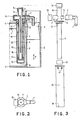
- the letter V denotes a tank, closed above by a cover C, in which, by arrangements well known per se and which are neither described nor shown here, a constant level L of gasoline is maintained .
- the letter D designates a diffuser intended to be connected to the suction manifold of a carburetion engine to be traversed by the aspirated air, flowing in the direction shown by the arrow F.
- the diffuser D is shaped like a tube of Venturi and it has a restricted section R. In this restricted section R is arranged the flow nozzle 1 of the sprayer.
- this nozzle is curved by 90 ° and it is connected to a coupling sleeve 2 which passes through a corresponding hole in the wall of the diffuser D to connect to the other parts of the sprayer.
- this arrangement which is advantageous from the point of view of construction, is not necessary, and the flow nozzle 1 could also be manufactured in one piece with other parts of the sprayer.
- the sprayer has a first vertical tube 4 which passes through the cover C of the tank V and plunges into the latter.
- the tube 4 has a lateral connection 5 to which is joined the coupling sleeve 2 of the flow spout 1.
- the tube 4 carries a calibrated nozzle 13 constituting the fuel nozzle of the sprayer.
- the vertical tube 4 also extends upwards by a section 6 which opens into the atmosphere and carries at its upper end a calibrated nozzle 14 constituting a primary air nozzle.
- the tube 4 has a connector 7, opposite to the connector 5, which opens to the atmosphere and carries a calibrated nozzle 15 constituting a secondary air jet.
- the vertical tube 4 is subdivided inside by a dividing wall 8 which extends over part of its height, dividing the tube 4 into a section 9 communicating with the flow nozzle 1 and with the primary air jet 14, and a section 10 communicating with the secondary air jet 15.
- the vertical tube 4 finally carries, outside, a pair of flanges 11 and 12. It has been specified that the parts 6, 7 and 8 relate to the particular form shown, because they are not necessary to achieve the main object of the invention, so it can also be assumed that they are lacking, in whole or in part, in simplified embodiments. In these simplified forms the tube 4 should be blind in correspondence with the missing sprinkler (s).
- the sprayer finally comprises a second vertical tube 16, the upper end of which is joined to the flanges 11 and 12 and communicates with the atmosphere of the tank V, above the filling level L, through openings 17.
- the end bottom of the tube 16 is closed by a bottom 18 in which a calibrated hole has been formed 19.
- the internal diameter of the tube 16 is somewhat larger than the external diameter of the fuel nozzle 13 mounted on the lower end of the vertical tube 4. Between the vertical tubes 4 and 16 there is a gap 20.
- the gas jet 13 of the sprayer (which determines the flow of gasoline sucked , as a function of the depression existing in the restricted section R of the diffuser r D and as a function of the hydraulic load to which it is subjected) is no more subject, as in known carburetors, to a constant load corresponding to the level L of filling of the tank V, but to a variable load corresponding to the level M of the gasoline in the gap 20, which level is reduced to the increase in the air flow sucked by the engine.
- This effect is antagonistic to the tendency of the flowed mixture to get richer when the flow of the sucked air increases, and therefore, as we includes, an appropriate proportioning of the different parts of the sprayer, and in particular of the fuel nozzle 13 and of the calibrated hole 19, makes it possible to achieve the course considered most suitable for the composition of the mixture delivered, according to the engine speed.
- the content of the gap 20 also introduces a favorable effect in the operation at a transient regime, be it acceleration or deceleration.
- the level M in the gap 20 must be reduced from the higher level corresponding to the initial speed of the engine to the reduced level corresponding to the higher final speed, and all the quantity of petrol which corresponds to this level variation is debited to the motor in addition during the acceleration phase.
- the level M in the gap 20 must rise from the level corresponding to the initial speed of the engine to the higher level corresponding to the reduced final speed, and all the quantity of petrol which corresponds this level variation is subtracted from the motor supply during the deceleration phase.
- This behavior is favorable, be it in terms of performance or in terms of economy, and its intensity can be adjusted by appropriately choosing the capacity of the gap 20.
- the secondary air jet 15 communicating with the section 10 of the tube 4 divided by the wall 8, it is noted that, by the effect of the depression which is established in the tube 4, a certain amount of air is sucked by the nozzle 15, descends in section 10 of the tube 4 and goes back in section 9 with the gasoline, bubbling in the latter and promoting its vaporization. In this way the spout 1 flows into the diffuser D of the gasoline already partly mixed with air and vaporized, to the advantage of the homogeneity of the mixture which finally forms.
- the presence of the secondary air jet 15 introduces an additional element which can be adjusted to obtain the metering conditions considered most suitable. This effect can also be achieved with an extension relatively reduced towards the bottom of the dividing wall 8. When there is the primary air jet 14, air is sucked through it too, and this air mixes in the flow nozzle 1 with the mixture already formed by gasoline and air; this introduces yet another element for adjusting the dosage.
- the importance of this effect can be proportional to the actual needs by appropriately dimensioning the capacity of the section 10 of the tube 4.
- the delivery to the engine of said additional quantity of petrol is more effective than the injection of '' an equal amount of gasoline carried out by a usual return pump, because the latter injects the fuel under a very reduced pressure, and therefore without it being able to spray and vaporize in an effective way, so that it does not can't be used in the best way.
- the additional quantity of gasoline delivered by the sprayer according to the invention is sucked through the flow nozzle 1 located in the restricted section of the diffuser D, and therefore in the best mixing conditions.
- the sprayer according to the invention is compact and of simple construction, and it is easy to access all of its parts for adjustment and for cleaning.
Landscapes
- Engineering & Computer Science (AREA)
- Chemical & Material Sciences (AREA)
- Combustion & Propulsion (AREA)
- Mechanical Engineering (AREA)
- General Engineering & Computer Science (AREA)
- Nozzles (AREA)
- Output Control And Ontrol Of Special Type Engine (AREA)
- Pressure-Spray And Ultrasonic-Wave- Spray Burners (AREA)
- Catching Or Destruction (AREA)
- Control Of The Air-Fuel Ratio Of Carburetors (AREA)
Applications Claiming Priority (2)
| Application Number | Priority Date | Filing Date | Title |
|---|---|---|---|
| IT67876/88A IT1224458B (it) | 1988-09-30 | 1988-09-30 | Spuzzatore corretto per il carburatore di un motore a carburazione |
| IT6787688 | 1988-09-30 |
Publications (3)
| Publication Number | Publication Date |
|---|---|
| EP0361600A2 true EP0361600A2 (de) | 1990-04-04 |
| EP0361600A3 EP0361600A3 (en) | 1990-06-20 |
| EP0361600B1 EP0361600B1 (de) | 1992-07-08 |
Family
ID=11306007
Family Applications (1)
| Application Number | Title | Priority Date | Filing Date |
|---|---|---|---|
| EP89202378A Expired - Lifetime EP0361600B1 (de) | 1988-09-30 | 1989-09-21 | Zerstäubungsdüse für Vergaser einer gemischverdichtenden Brennkraftmaschine |
Country Status (6)
| Country | Link |
|---|---|
| US (1) | US4978479A (de) |
| EP (1) | EP0361600B1 (de) |
| JP (1) | JPH02264144A (de) |
| DE (1) | DE68902031T2 (de) |
| ES (1) | ES2033082T3 (de) |
| IT (1) | IT1224458B (de) |
Families Citing this family (1)
| Publication number | Priority date | Publication date | Assignee | Title |
|---|---|---|---|---|
| US8697305B2 (en) * | 2009-03-16 | 2014-04-15 | Kabushiki Kaisha Toyoda Jidoshokki | Fuel cell system |
Family Cites Families (13)
| Publication number | Priority date | Publication date | Assignee | Title |
|---|---|---|---|---|
| FR485405A (fr) * | 1917-05-09 | 1918-01-09 | Marius Jean Baptiste Barbarou | Perfectionnements aux carburateurs pour moteurs à explosions |
| US1562651A (en) * | 1918-01-02 | 1925-11-24 | Stromberg Motor Devices Co | Carburetor |
| US1613257A (en) * | 1919-10-18 | 1927-01-04 | Packard Motor Car Co | Carbureting device |
| BE356232A (de) * | 1928-11-29 | |||
| US2043514A (en) * | 1932-11-25 | 1936-06-09 | Solex | Carburetor |
| US2346711A (en) * | 1941-12-15 | 1944-04-18 | Ladimir F Stupecky | Carburetor |
| US3387831A (en) * | 1965-10-23 | 1968-06-11 | Acf Ind Inc | Carburetor anti-surge device |
| US3940460A (en) * | 1974-02-14 | 1976-02-24 | Graybill Clinton L | Air-valve type carburetor |
| US4001356A (en) * | 1975-08-22 | 1977-01-04 | Clinton Graybill | Variable venturi downdraft carburetor |
| JPS5372935A (en) * | 1976-12-10 | 1978-06-28 | Hitachi Ltd | Carburetor |
| JPS6027822B2 (ja) * | 1977-05-13 | 1985-07-01 | 自動車機器技術研究組合 | 気化器の始動装置 |
| IT1144263B (it) * | 1981-07-02 | 1986-10-29 | Marco Morini | Carburatore per motori a combustione interna |
| US4515734A (en) * | 1983-01-28 | 1985-05-07 | Rock Howard P | Fuel efficient, low pollution carburetor and methods |
-
1988
- 1988-09-30 IT IT67876/88A patent/IT1224458B/it active
-
1989
- 1989-09-13 US US07/406,571 patent/US4978479A/en not_active Expired - Fee Related
- 1989-09-21 DE DE8989202378T patent/DE68902031T2/de not_active Expired - Fee Related
- 1989-09-21 ES ES198989202378T patent/ES2033082T3/es not_active Expired - Lifetime
- 1989-09-21 EP EP89202378A patent/EP0361600B1/de not_active Expired - Lifetime
- 1989-09-29 JP JP1255099A patent/JPH02264144A/ja active Pending
Also Published As
| Publication number | Publication date |
|---|---|
| DE68902031D1 (de) | 1992-08-13 |
| JPH02264144A (ja) | 1990-10-26 |
| EP0361600A3 (en) | 1990-06-20 |
| EP0361600B1 (de) | 1992-07-08 |
| DE68902031T2 (de) | 1993-02-11 |
| IT1224458B (it) | 1990-10-04 |
| IT8867876A0 (it) | 1988-09-30 |
| US4978479A (en) | 1990-12-18 |
| ES2033082T3 (es) | 1993-03-01 |
Similar Documents
| Publication | Publication Date | Title |
|---|---|---|
| EP0361600B1 (de) | Zerstäubungsdüse für Vergaser einer gemischverdichtenden Brennkraftmaschine | |
| FR2529621A1 (fr) | Ensemble de carburation a colonne liquide et procede d'alimentation en carburant d'un moteur a combustion interne | |
| FR2580190A1 (fr) | Filtre a carburant et circuit d'alimentation en carburant equipe de ce filtre | |
| EP0361599B1 (de) | Satz zur Versorgung einer gemischverdichtenden Brennkraftmaschine während besonderer Betriebsphasen | |
| EP0218515B1 (de) | Vergaser für Brennkraftmaschine | |
| EP0060184A1 (de) | Aufladung von Zweitakt-Brennkraftmaschinen | |
| FR2698662A1 (fr) | Dispositif assurant la combustion complète du mélange d'air et de carburant liquide alimentant les moteurs à combustion interne. | |
| BE409078A (de) | ||
| BE534613A (de) | ||
| CH137555A (fr) | Carburateur pour moteurs à combustion interne. | |
| BE363573A (de) | ||
| BE340823A (de) | ||
| BE787603A (fr) | Procede et appareil pour former un melange de carburant et d'air au moyen d'energie sonique. | |
| BE358441A (de) | ||
| FR2461823A1 (fr) | Dispositif de correction de carburation pour moteur a explosion | |
| BE415587A (de) | ||
| JPH04191456A (ja) | ダイヤフラム式気化器を備えたエンジンの始動装置 | |
| BE399299A (de) | ||
| BE410650A (de) | ||
| BE417674A (de) | ||
| BE378891A (de) | ||
| FR2696785A1 (fr) | Carburateur à membrane avec adaptation altimétrique. | |
| CH88434A (fr) | Carburateur pour moteurs à combustion interne. | |
| BE393069A (de) | ||
| BE366497A (de) |
Legal Events
| Date | Code | Title | Description |
|---|---|---|---|
| PUAI | Public reference made under article 153(3) epc to a published international application that has entered the european phase |
Free format text: ORIGINAL CODE: 0009012 |
|
| AK | Designated contracting states |
Kind code of ref document: A2 Designated state(s): DE ES FR GB |
|
| PUAL | Search report despatched |
Free format text: ORIGINAL CODE: 0009013 |
|
| AK | Designated contracting states |
Kind code of ref document: A3 Designated state(s): DE ES FR GB |
|
| 17P | Request for examination filed |
Effective date: 19901210 |
|
| 17Q | First examination report despatched |
Effective date: 19910417 |
|
| GRAA | (expected) grant |
Free format text: ORIGINAL CODE: 0009210 |
|
| AK | Designated contracting states |
Kind code of ref document: B1 Designated state(s): DE ES FR GB |
|
| REF | Corresponds to: |
Ref document number: 68902031 Country of ref document: DE Date of ref document: 19920813 |
|
| GBT | Gb: translation of ep patent filed (gb section 77(6)(a)/1977) | ||
| REG | Reference to a national code |
Ref country code: ES Ref legal event code: FG2A Ref document number: 2033082 Country of ref document: ES Kind code of ref document: T3 |
|
| PLBE | No opposition filed within time limit |
Free format text: ORIGINAL CODE: 0009261 |
|
| STAA | Information on the status of an ep patent application or granted ep patent |
Free format text: STATUS: NO OPPOSITION FILED WITHIN TIME LIMIT |
|
| 26N | No opposition filed | ||
| PGFP | Annual fee paid to national office [announced via postgrant information from national office to epo] |
Ref country code: GB Payment date: 19930915 Year of fee payment: 5 |
|
| PGFP | Annual fee paid to national office [announced via postgrant information from national office to epo] |
Ref country code: ES Payment date: 19930922 Year of fee payment: 5 |
|
| PGFP | Annual fee paid to national office [announced via postgrant information from national office to epo] |
Ref country code: FR Payment date: 19930929 Year of fee payment: 5 |
|
| PGFP | Annual fee paid to national office [announced via postgrant information from national office to epo] |
Ref country code: DE Payment date: 19931022 Year of fee payment: 5 |
|
| PG25 | Lapsed in a contracting state [announced via postgrant information from national office to epo] |
Ref country code: GB Effective date: 19940921 |
|
| PG25 | Lapsed in a contracting state [announced via postgrant information from national office to epo] |
Ref country code: ES Free format text: LAPSE BECAUSE OF THE APPLICANT RENOUNCES Effective date: 19940922 |
|
| GBPC | Gb: european patent ceased through non-payment of renewal fee |
Effective date: 19940921 |
|
| PG25 | Lapsed in a contracting state [announced via postgrant information from national office to epo] |
Ref country code: FR Effective date: 19950531 |
|
| PG25 | Lapsed in a contracting state [announced via postgrant information from national office to epo] |
Ref country code: DE Effective date: 19950601 |
|
| REG | Reference to a national code |
Ref country code: FR Ref legal event code: ST |
|
| REG | Reference to a national code |
Ref country code: ES Ref legal event code: FD2A Effective date: 20001102 |