EP0361631B1 - A spare tire cover - Google Patents
A spare tire cover Download PDFInfo
- Publication number
- EP0361631B1 EP0361631B1 EP19890250042 EP89250042A EP0361631B1 EP 0361631 B1 EP0361631 B1 EP 0361631B1 EP 19890250042 EP19890250042 EP 19890250042 EP 89250042 A EP89250042 A EP 89250042A EP 0361631 B1 EP0361631 B1 EP 0361631B1
- Authority
- EP
- European Patent Office
- Prior art keywords
- cover
- wall
- tire
- spare tire
- tire cover
- Prior art date
- Legal status (The legal status is an assumption and is not a legal conclusion. Google has not performed a legal analysis and makes no representation as to the accuracy of the status listed.)
- Expired - Lifetime
Links
- 239000000463 material Substances 0.000 claims description 4
- XLYOFNOQVPJJNP-UHFFFAOYSA-N water Substances O XLYOFNOQVPJJNP-UHFFFAOYSA-N 0.000 description 6
- 239000004744 fabric Substances 0.000 description 2
- 238000000034 method Methods 0.000 description 2
- 238000010276 construction Methods 0.000 description 1
- 239000000356 contaminant Substances 0.000 description 1
- 230000008602 contraction Effects 0.000 description 1
- 230000001771 impaired effect Effects 0.000 description 1
- 239000002184 metal Substances 0.000 description 1
- 230000004048 modification Effects 0.000 description 1
- 238000012986 modification Methods 0.000 description 1
Images


Classifications
-
- B—PERFORMING OPERATIONS; TRANSPORTING
- B62—LAND VEHICLES FOR TRAVELLING OTHERWISE THAN ON RAILS
- B62D—MOTOR VEHICLES; TRAILERS
- B62D43/00—Spare wheel stowing, holding, or mounting arrangements
- B62D43/005—Protective coverings for spare wheels
Definitions
- the present invention relates to a cover for a spare tire to be carried outside a vehicle body of a carriage, particularly a four-wheeled automobile and the like.
- FIG. 6 is a perspective view illustrating one embodiment, wherein the cover b has an opening c and a cut-out portion d respectively defined in its reverse surface (vehicle body side) for facilitating its attachment.
- the opening c has a rubber thread e arranged around the circumference of its edge portion.
- the opening c is enlarged to cover a spare tire a and the spare tire is accommodated inside the cover with the cut-out portion d facing downwardly, whereby wrapping the spare tire a with the tire cover b.
- the tire cover b of the above construction suffered from a drawback that a rain water could enter into the cover to wash away contaminants off the spare tire and consequently a resultant fouled water flowed out of the cut-out portion d to contaminate the vehicle body.
- the tire cover b may be impaired aesthetically when attached to the spare tire b in a twisted form. Consequently, adjusting the position of the tire cover with the cover secured around the tire was almost impossible, since the tire cover b is excessively tightly secured around the outer circumference of the spare tire under the tension from the rubber thread e.
- US-A-16 29 777 discloses a spare tire cover, which consists of a front wall, a rear wall and a circumferential wall connecting said front and rear walls.
- the front wall and the circumferential wall consist of separate upper and lower portions.
- the upper portion can be opended and closes. However, said portion is not freely bendable and therefore, it becomes a hindrance. Further, the upper portion of said cover is caused to engage the lower portion by means of a special metal tool and special members. Therefore, such an operation is not so simple.
- the present invention has been made with the above problems in the prior art as a background, and its object is to provide a spare tire cover which can eliminate the above drawbacks by allowing a upper half of the tire cover to be tilted and opened in the direction of user.
- the present invention provides a spare tire cover, said tire cover being secured in place outside a vehicle body, wherein said cover is made of a shape-retaining material formed into a substantially cylindrical body consisting of a front wall, a rear wall and a circumferential wall connecting said front and rear walls where said front wall and said circumferential wall consist of separate upper an lower portions, characterized in that said rear wall is structured to be freely bendable along a diameter axis and whereby in the closed position of the tire cover overlapping portions are provided between the two separate front wall portions and circumferential portions respectively, said overlapping portions being provided with detachable tape.
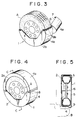
- a numeral 1 represents a tire cover of the present invention.
- the cover 1 is formed from a material of shape-retaining characteristics (or any other materials may be used) substantially in a cylindrical configuration, and comprises a bottom wall 2 that faces toward a vehicle body side and has an opening 3 defined therethrough, a circumferencial wall 4 and a upper wall 5.
- the bottom wall 2 and the circumferential wall 4 are split substantially into equal halves along a parting plane 6, which arrangement allows the upper wall 5 to be folded in the direction of user along the parting plane 6 (see FIG. 2).
- the bottom wall 2 is split into a upper bottom wall 2a and a lower bottom wall 2b
- the circumferential wall 4 is split into a upper circumferential wall 4a and a lower circumferential wall 4b respectively.
- the upper bottom wall 2a and the upper circumferential wall 4a are provided with an overlapping portion which extends downwardly from the parting plane 6.
- the lower bottom wall 2b and the lower circumferential wall 4b are provided horizontally along its upper surface edge portion with an engaging portion, i.e., a tape 8b with freely detachable characteristics.
- a similar tape 8a applied over the undersurface of the overlapping portion 7 is made to adhere to the tape 8b when the upper half of the cover is caused to stand uprightly.
- the tape 8 comprises a pair of tapes, one tape having, for example, a multiplicity of small hooks embedded thereover, and other tape having a multiplicity of small rings embedded thereover which are brought into an off engagement with above hooks, either of pair of tapes 8b being adhered to the undersurface of the overlapping portion 7 and other of the pair of tapes 8b being adhered to the surface of the upper edge of the lower bottom wall 2b and the circumferential wall 4b adjacent to the parting plane 6.
- These tapes functions to engage with and disengage from an object (i.e., having freely detachable function) when two tapes are pressed and then peeled off each other.
- an object i.e., having freely detachable function
- the tape 8 may be replaced with an alternative type engaging member or an engaging structure.
- a numeral 9 represents a drain hole defined through the lower end of the tire cover 1 adjacent to its upper wall 5 for draining out a rain water ingressed into the tire cover 1 through the hole 9.
- the present invention is constituted as above, and the spare tire may be attached in a following manner.
- the tape 8, which applied between the overlapping portion 7 and the upper edge portions of the lower bottom wall 2b and of the lower circumferential wall 4b is first peeled off, and then the upper half of the tire cover 1 is folded for expansion in the direction of user as shown in FIG. 2. Subsequently, the tire cover 1 is raised upwardly by a user grasping with hands opposite ends of the upper wall 5 of this folded portion, and the spare tire A which has been attached at the rear portion of the vehicle body is accommodated in the lower half section of the tire cover 1. Lastly, the upper half section of the tire cover is erected uprightly and applied over the spare tire A as shown in FIG. 4 and then the overlapping portion 7 is brought into engagement with the above-described upper edge portion through the tape and thereby completing a cover attaching procedure.
- a rain water ingressed into the interior of the tire cover 1 is drained out through a drain hole 9 defined through the lower end of the tire cover, whereby preventing the rear bumper B from being contaminated with a foulded water
- the spare tire cover may be fixed in position using a simple procedure, i.e., the upper half section of the tire cover is folded in the direction of user and then the spare tire is accommodated in its lower half section, and the upper half section is erected uprightly and secured to the lower half section, and consequently no obstacle will be present for attaching the tire even when the tire cover is deformed or contracted.
- the tire cover is not attached tightly around the circumferential surface of the spare tire, as is frequently observed in the case of traditional tire cover utilizing a rubber thread to lash an opening in the rear surface, and consequently the adjustment of the spare tire for its position can be made easily even when the tire has been put into position in a twisted state.
Landscapes
- Engineering & Computer Science (AREA)
- Chemical & Material Sciences (AREA)
- Combustion & Propulsion (AREA)
- Transportation (AREA)
- Mechanical Engineering (AREA)
- Body Structure For Vehicles (AREA)
- Packaging Of Annular Or Rod-Shaped Articles, Wearing Apparel, Cassettes, Or The Like (AREA)
- Tires In General (AREA)
Applications Claiming Priority (2)
| Application Number | Priority Date | Filing Date | Title |
|---|---|---|---|
| JP63243517A JP2701366B2 (ja) | 1988-09-28 | 1988-09-28 | スペアタイヤのカバー |
| JP243517/88 | 1988-09-28 |
Publications (3)
| Publication Number | Publication Date |
|---|---|
| EP0361631A2 EP0361631A2 (en) | 1990-04-04 |
| EP0361631A3 EP0361631A3 (en) | 1990-10-17 |
| EP0361631B1 true EP0361631B1 (en) | 1994-01-26 |
Family
ID=17105086
Family Applications (1)
| Application Number | Title | Priority Date | Filing Date |
|---|---|---|---|
| EP19890250042 Expired - Lifetime EP0361631B1 (en) | 1988-09-28 | 1989-09-21 | A spare tire cover |
Country Status (3)
| Country | Link |
|---|---|
| EP (1) | EP0361631B1 (ja) |
| JP (1) | JP2701366B2 (ja) |
| DE (1) | DE68912698T2 (ja) |
Families Citing this family (6)
| Publication number | Priority date | Publication date | Assignee | Title |
|---|---|---|---|---|
| US5314200A (en) * | 1993-03-01 | 1994-05-24 | Phillips Vern L | Multi-purpose trailer apparatus |
| AU652113B3 (en) * | 1993-12-09 | 1994-08-11 | Van Bits Pty Ltd | Spare wheel cover |
| GB2282578B (en) * | 1994-09-05 | 1996-05-08 | Graham Andrew Macdonald | Wheel cleaning cover |
| JP3330041B2 (ja) * | 1996-12-26 | 2002-09-30 | 本田技研工業株式会社 | 自動車のスペアタイヤカバー |
| JP4785131B2 (ja) * | 2006-03-20 | 2011-10-05 | ダイハツ工業株式会社 | 車両におけるスペアタイヤ装置 |
| JP6337340B2 (ja) * | 2014-12-02 | 2018-06-06 | トヨタ車体株式会社 | スペアタイヤ固定部、スペアタイヤ収容システム及び車両 |
Family Cites Families (7)
| Publication number | Priority date | Publication date | Assignee | Title |
|---|---|---|---|---|
| US2440805A (en) * | 1948-05-04 | Pjlastic tire | ||
| US1629777A (en) * | 1925-12-02 | 1927-05-24 | Dahl Christ | Tire carrier and protector |
| US1897888A (en) * | 1930-05-31 | 1933-02-14 | Keith C Bright | Tire trunk |
| DE1898318U (de) * | 1964-03-21 | 1964-08-06 | Ver Deutsche Metallwerke Ag | Reifenverkleidung aus kunststoff, vorzugsweise fuer im koffer- bzw. laderaum untergebrachte pkw-ersatzreifen. |
| JPS6114181U (ja) * | 1984-06-30 | 1986-01-27 | 技研株式会社 | 自動車の予備タイヤ用カバ− |
| JPH023984Y2 (ja) * | 1985-09-30 | 1990-01-30 | ||
| DE8624009U1 (de) * | 1986-09-06 | 1987-01-15 | Köll, Philipp O., 8260 Mühldorf | Reserverad-Schutzvorrichtung |
-
1988
- 1988-09-28 JP JP63243517A patent/JP2701366B2/ja not_active Expired - Fee Related
-
1989
- 1989-09-21 DE DE1989612698 patent/DE68912698T2/de not_active Expired - Fee Related
- 1989-09-21 EP EP19890250042 patent/EP0361631B1/en not_active Expired - Lifetime
Also Published As
| Publication number | Publication date |
|---|---|
| EP0361631A3 (en) | 1990-10-17 |
| JPH0292787A (ja) | 1990-04-03 |
| DE68912698D1 (de) | 1994-03-10 |
| EP0361631A2 (en) | 1990-04-04 |
| JP2701366B2 (ja) | 1998-01-21 |
| DE68912698T2 (de) | 1994-05-05 |
Similar Documents
| Publication | Publication Date | Title |
|---|---|---|
| US5356191A (en) | Protective cover for the windshield of an automobile | |
| USD391524S (en) | Exterior shell of a vehicle roof | |
| USD370650S (en) | Vehicle window shade | |
| EP0361631B1 (en) | A spare tire cover | |
| CA2374464A1 (en) | Metallo-plastic clip for attaching vehicle roofs and accessories to the body of a vehicle | |
| HK78887A (en) | Umbrella frame | |
| US4802804A (en) | Plastic clip with resilient thread segments and hinged clasp | |
| USD330697S (en) | Automobile sunshade cover | |
| USD368652S (en) | Tarpaulin strap ends | |
| USD352920S (en) | Exterior shell for a recreational vehicle fold out extension | |
| USD339781S (en) | Cover for shutting off sunshine on roof of car | |
| KR960002170Y1 (ko) | 자동차용 커버 | |
| KR200176495Y1 (ko) | 자동차 도어용 보호판 | |
| KR0136541Y1 (ko) | 자동차의 가변식 사이드 미러 커버 | |
| KR19990025617U (ko) | 자동차커버 | |
| JPH0340161Y2 (ja) | ||
| JPH0135164Y2 (ja) | ||
| KR19980037231A (ko) | 자동차의 트렁크 리드용 비품 고정기구 | |
| JP2552237Y2 (ja) | 自転車かごカバー | |
| USD384933S (en) | Retractable roof-top seal for a vehicle | |
| JPH0754071Y2 (ja) | 車 両 | |
| KR200247767Y1 (ko) | 골프백 커버 | |
| JP2604847Y2 (ja) | 伸縮式ロッド装置 | |
| KR950007705Y1 (ko) | 자동접음식 자동차 커버 | |
| KR960002169Y1 (ko) | 자동차용 커버 |
Legal Events
| Date | Code | Title | Description |
|---|---|---|---|
| PUAI | Public reference made under article 153(3) epc to a published international application that has entered the european phase |
Free format text: ORIGINAL CODE: 0009012 |
|
| AK | Designated contracting states |
Kind code of ref document: A2 Designated state(s): DE GB IT |
|
| PUAL | Search report despatched |
Free format text: ORIGINAL CODE: 0009013 |
|
| AK | Designated contracting states |
Kind code of ref document: A3 Designated state(s): DE GB IT |
|
| 17P | Request for examination filed |
Effective date: 19901227 |
|
| RAP1 | Party data changed (applicant data changed or rights of an application transferred) |
Owner name: SUZUKI MOTOR CORPORATION |
|
| 17Q | First examination report despatched |
Effective date: 19920313 |
|
| GRAA | (expected) grant |
Free format text: ORIGINAL CODE: 0009210 |
|
| AK | Designated contracting states |
Kind code of ref document: B1 Designated state(s): DE GB IT |
|
| ITF | It: translation for a ep patent filed | ||
| REF | Corresponds to: |
Ref document number: 68912698 Country of ref document: DE Date of ref document: 19940310 |
|
| PLBE | No opposition filed within time limit |
Free format text: ORIGINAL CODE: 0009261 |
|
| STAA | Information on the status of an ep patent application or granted ep patent |
Free format text: STATUS: NO OPPOSITION FILED WITHIN TIME LIMIT |
|
| 26N | No opposition filed | ||
| REG | Reference to a national code |
Ref country code: GB Ref legal event code: IF02 |
|
| PGFP | Annual fee paid to national office [announced via postgrant information from national office to epo] |
Ref country code: DE Payment date: 20050915 Year of fee payment: 17 |
|
| PGFP | Annual fee paid to national office [announced via postgrant information from national office to epo] |
Ref country code: GB Payment date: 20050921 Year of fee payment: 17 |
|
| PGFP | Annual fee paid to national office [announced via postgrant information from national office to epo] |
Ref country code: IT Payment date: 20060930 Year of fee payment: 18 |
|
| PG25 | Lapsed in a contracting state [announced via postgrant information from national office to epo] |
Ref country code: DE Free format text: LAPSE BECAUSE OF NON-PAYMENT OF DUE FEES Effective date: 20070403 |
|
| GBPC | Gb: european patent ceased through non-payment of renewal fee |
Effective date: 20060921 |
|
| PG25 | Lapsed in a contracting state [announced via postgrant information from national office to epo] |
Ref country code: GB Free format text: LAPSE BECAUSE OF NON-PAYMENT OF DUE FEES Effective date: 20060921 |
|
| PG25 | Lapsed in a contracting state [announced via postgrant information from national office to epo] |
Ref country code: IT Free format text: LAPSE BECAUSE OF NON-PAYMENT OF DUE FEES Effective date: 20070921 |