EP0361674A1 - Source lumineuse - Google Patents
Source lumineuse Download PDFInfo
- Publication number
- EP0361674A1 EP0361674A1 EP89308487A EP89308487A EP0361674A1 EP 0361674 A1 EP0361674 A1 EP 0361674A1 EP 89308487 A EP89308487 A EP 89308487A EP 89308487 A EP89308487 A EP 89308487A EP 0361674 A1 EP0361674 A1 EP 0361674A1
- Authority
- EP
- European Patent Office
- Prior art keywords
- light
- lamp
- light source
- coating
- interference film
- Prior art date
- Legal status (The legal status is an assumption and is not a legal conclusion. Google has not performed a legal analysis and makes no representation as to the accuracy of the status listed.)
- Withdrawn
Links
Images


Classifications
-
- H—ELECTRICITY
- H01—ELECTRIC ELEMENTS
- H01K—ELECTRIC INCANDESCENT LAMPS
- H01K1/00—Details
- H01K1/28—Envelopes; Vessels
- H01K1/32—Envelopes; Vessels provided with coatings on the walls; Vessels or coatings thereon characterised by the material thereof
-
- H—ELECTRICITY
- H01—ELECTRIC ELEMENTS
- H01K—ELECTRIC INCANDESCENT LAMPS
- H01K1/00—Details
- H01K1/28—Envelopes; Vessels
- H01K1/32—Envelopes; Vessels provided with coatings on the walls; Vessels or coatings thereon characterised by the material thereof
- H01K1/325—Reflecting coating
Definitions
- the present invention relates generally to a light source and a reflector, and more particularly to a light source for transmitting selected colored light.
- the reflecting light source comprises a tungsten halogen lamp 11 and a reflector 12.
- the reflector 12 is made of glass and is of paraboloid form.
- the tungsten halogen lamp 11 comprises a sealed glass bulb 13 with a tungsten filament 14 housed in the glass blub 13.
- a base 11a of the tungsten halogen lamp 11 is mounted in a cylindrical base 12a of the reflector 12 so that the tungsten filament 14 is positioned around the focal point of the parabolic reflector 12.
- the reflecting light source further comprises two kinds of light interference films 15 and 16 coated on the glass bulb 13 of the lamp 11 and the reflector 12, respectively.
- the first light interference film 15 is a visible light transparency/infrared-ray reflective film which is made of semiconductors, such as silicon oxide (SiO2), titanium oxide (TiO2), etc.
- the second light interference film 16 is a visible light reflective/infrared-ray transparency film.
- the visible light reflective/infrared-ray transparency film 16 comprises multiple layers of two kinds of different refractive index layers which are alternately disposed on the reflector.
- Visible light emitted from the filament 14 passes through the first light interference film 15. The visible light is then reflected by the second light interference film 16. Thus, the visible light is radiated toward the front of the reflector 12.
- Infrared-rays emitted from the filament 14 are almost all reflected by the first light interference film 15 toward the filament.
- the infrared-rays thus reflected then heat the filament 14 so that the light emitting efficiency of the filament 14 is increased.
- a small amount of the infrared-rays may leak from the lamp 11 by passing through the first light interference film 15.
- the infrared-rays thus leaked then pass through the second light interference film 16 and the glass reflector 12. Thus, the infrared-rays are prevented from radiating to the front of the reflector 12.
- the conventional reflecting light source has a drawback, as described below.
- the interference of light in these light interference films 15 and 16 becomes weak.
- the first light interference film 15 on the lamp 11 fails to reflect the infrared-rays when the infrared-rays are radiated thereto at an incidence angle exceeding a prescribed angle.
- the infrared-rays radiated to the first light interference film 15 at a large incidence angle pass through the first light interference film 15.
- the infrared-rays thus passing through the first light interference film 15 are also radiated to the second light interference film 16 on the reflector 12 at a large incidence angle.
- the second light interference film 16 fails to transmit the infrared-rays radiated thereto at a large incidence angle.
- the infrared-rays radiated to the second light interference film 16 at a large incidence angle are reflected by the second light interference film 16.
- the present invention seeks to provide a light source which is able to effectively reduce the amount of infrared-rays radiated toward the front of the light source.
- a light source comprises an electric lamp having a filament which, when energised, emits light of different wave lengths; a shaped member around the lamp and having a light reflecting surface arranged on it such that light from the lamp which falls upon the surface is reflected in a direction away from the lamp; a coating on the surface of the lamp which transmits light of a specific range of wave lengths and reflects light of other wave lengths back into the lamp; characterised in that the light reflecting surface is positioned on the shaped member such that light of the specific range of wave length transmitted by the coating is reflected and light emitted by the lamp outside of said specific range of wave lengths does not impinge on the light reflecting surface and, therefore, is not reflected.
- a reflecting light source comprises a tungsten halogen lamp 11 and a shaped member 12.
- the member 12 is made of glass and is of parabolic form.
- the tungsten halogen lamp 11 comprises a sealed glass bulb 13 and a tungsten filament 14 housed in the glass bulb 13.
- a base 11a of the tungsten halogen lamp 11 is mounted in a cylindrical base 12a of the reflector 12 so that the tungsten filament 14 is positioned around the focal point of the parabolic member 12.
- the reflecting light source further comprises a light interference film 15a and a mirror 16a.
- the light interference film 15a and the mirror 16a are coated on the glass bulb 13 of the lamp 11 and the member 12, respectively.
- the light interference film 15a is a conventional light interference film like the visible light transparency/infrared-ray reflective film which is used in the conventional reflecting light source as the first light interference film 15 (see Figure 1).
- the light interference film 15a comprises multiple layers of two kinds of different refractive index layers, e.g. titanium oxide (TiO2) layers and silicon oxide (SiO2) layers which are alternately disposed on the glass bulb 13.
- the light interference film 15a has a spectral selectivity so that light with a relatively long wave length passes therethrough but other light with a relatively short wave length is reflected thereby.
- the mirror 16a is an aluminium film.
- the aluminium film can be formed by, for example, a conventional deposition technique.
- the position of the mirror 16a is defined in a specific range along the axis of the reflector 12, as described below.
- the specific range of the mirror 16a will be described, as to a prescribed light band L ⁇ with a prescribed center wave length ⁇ , e.g., an infrared-ray which will be reflected by the light interference film 15a.
- the filament 14 emits light including the light band L ⁇ .
- the light band L ⁇ emitted from the filament 14 is radiated to the light interference film 15a.
- the light interference film 15 has an optical thickness D and a refractive index N.
- two luminous fluxs L1 and L2 are supposed.
- the first luminous flux L1 is radiated to the light interference film 15a at a relatively small incidence angle ⁇ 1.
- the second luminous flux L2 is radiated to the light interference film 15a at a relatively large incidence angle ⁇ 2 ( ⁇ 2 > ⁇ 1).
- the first and second luminous fluxs L1 and L2 goes into the light interference film 15a along a passage with a relatively short distance D1 and another passage with a relatively long distance D2 (D2 > D1), respectively.
- These distances D1 and D2 are almost defined by the optical thickness D and the refractive index N of the light interference film 15a and the incidence angles ⁇ 1 and ⁇ 2.
- the luminous flux L1 is reflected by the light interference film 15a, while the luminous flux L2 transmits through the light interference film 15a.
- a phase divergence ⁇ of the center wave length ⁇ of the light band L ⁇ varies in accordance with the distances e.g., D1 and D2 of the light passages in the light interference film 15a.
- the distance of light passage is defined by the optical thickness D and the refractive index N of the light interference film 15a and an incidence angle ⁇ of light, as described above.
- the phase divergence ⁇ is given by the following equation:
- the phase of the light in the light interference film 15a deviates toward the phase corresponding to a light with long wave length. Then, a luminous flux radiated to the light interference film 15a at an incidence angle smaller than the prescribed critical angle ⁇ x is reflected by the light interference film 15a. The other luminous flux radiated to the light interference film 15a at incidence angles larger than the prescribed critical angle ⁇ x pass through the light interference film 15a.
- the position of the mirror 16a can be defined into a specific range, according to the above equation.
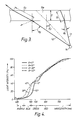
- FIGURE 2 it is supposed that luminous fluxes A and B emitted from the rear end and the front end of the filament 14 have the critical angle ⁇ x , respectively.
- the luminous fluxes A and B are of a specific light band to be reflected by the light interference film 15a, e.g., the infrared ray.
- the mirror 16a is defined in the range given by the luminous fluxes A and B.
- luminous fluxes of the specific light under the critical angle ⁇ x emitted from the filament 14 are reflected by the light interference film 15a.
- Other luminous fluxes of the specific light over the critical angle ⁇ x emitted from the filament 14 pass through the light interference film 15a.
- the other luminous fluxes thus passing through the light interference film 15a are not radiated to the mirror 16a.
- the range of the mirror 16a is defined so that the specific light band having a center wave length ⁇ and a prescribed band defined by a desired phase divergency ⁇ satisfies the following equation in relation to the incidence angle ⁇ to the light interference film 15a.
- the specific light e.g., the infrared ray is prevented from radiating to the front of the reflecting light source, even if the specific light passes through the light interference film 15a.
- a specific light band exceeding a optional wave length is easily prevented from radiating to the front of the reflecting light source.
- a desired light for example, a yellow color light, an orange color light or a red color light, is obtained in the front of the reflecting light source.
- FIGURE 4 shows the wavelength to light intensity characteristic of a test sample according to the present invention.
- the test sample was designed for selectively obtaining the yellow color light.
- the light interference film 15a (see FIGURE 2) reflects lights in the light band below the wavelength of about 530 nm at a prescribed range in reference to the light incidence angle.
- the light below the wavelength of about 530 nm corresponds to the blue color light.
- the light including the blue color light passing through the light interference film 15a are not applied to the mirror 16a.
- other light mainly including the red color light and the green color light, pass through the light interference film 15a and are then reflected by the mirror 16a.
- the reflected light including the red color light and the green color light, is seen as the yellow color light by the human eye.
- the test sample selectively obtained the yellow color light.
- the light interference film 15a is formed by the multiple layers of the titanium oxide (TiO2) layers and the silicon oxide (SiO2) layers in the embodiment.
- the light interference film 15a can be formed by multiple layers of zinc sulfide (ZnS) layers and magnesium fluoride (MgF) layers.
- the present invention can provide an extremely preferable reflecting light source.
Landscapes
- Optical Elements Other Than Lenses (AREA)
Applications Claiming Priority (2)
| Application Number | Priority Date | Filing Date | Title |
|---|---|---|---|
| JP63207410A JPH0256804A (ja) | 1988-08-23 | 1988-08-23 | 光源装置 |
| JP207410/88 | 1988-08-23 |
Publications (1)
| Publication Number | Publication Date |
|---|---|
| EP0361674A1 true EP0361674A1 (fr) | 1990-04-04 |
Family
ID=16539281
Family Applications (1)
| Application Number | Title | Priority Date | Filing Date |
|---|---|---|---|
| EP89308487A Withdrawn EP0361674A1 (fr) | 1988-08-23 | 1989-08-22 | Source lumineuse |
Country Status (3)
| Country | Link |
|---|---|
| EP (1) | EP0361674A1 (fr) |
| JP (1) | JPH0256804A (fr) |
| KR (1) | KR900003960A (fr) |
Cited By (1)
| Publication number | Priority date | Publication date | Assignee | Title |
|---|---|---|---|---|
| EP0663684A3 (fr) * | 1994-01-18 | 1995-12-13 | Patent Treuhand Ges Fuer Elektrische Gluehlampen Mbh | Lampe à réflecteur. |
Citations (2)
| Publication number | Priority date | Publication date | Assignee | Title |
|---|---|---|---|---|
| GB2144578A (en) * | 1983-08-01 | 1985-03-06 | Gen Electric | Incandescent lamps |
| WO1986002775A1 (fr) * | 1984-10-23 | 1986-05-09 | Duro-Test Corporation | Film a indice variable pour miroirs thermiques transparents |
-
1988
- 1988-08-23 JP JP63207410A patent/JPH0256804A/ja active Pending
-
1989
- 1989-08-22 EP EP89308487A patent/EP0361674A1/fr not_active Withdrawn
- 1989-08-23 KR KR1019890011965A patent/KR900003960A/ko not_active Ceased
Patent Citations (2)
| Publication number | Priority date | Publication date | Assignee | Title |
|---|---|---|---|---|
| GB2144578A (en) * | 1983-08-01 | 1985-03-06 | Gen Electric | Incandescent lamps |
| WO1986002775A1 (fr) * | 1984-10-23 | 1986-05-09 | Duro-Test Corporation | Film a indice variable pour miroirs thermiques transparents |
Cited By (2)
| Publication number | Priority date | Publication date | Assignee | Title |
|---|---|---|---|---|
| EP0663684A3 (fr) * | 1994-01-18 | 1995-12-13 | Patent Treuhand Ges Fuer Elektrische Gluehlampen Mbh | Lampe à réflecteur. |
| US5548182A (en) * | 1994-01-18 | 1996-08-20 | Patent-Treuhand-Gesellschaft F. Elektrische Gluehlampen Mbh | Reflector lamp specifically adapted for combination with a reflector lamp-lamp luminaire or fixture |
Also Published As
| Publication number | Publication date |
|---|---|
| JPH0256804A (ja) | 1990-02-26 |
| KR900003960A (ko) | 1990-03-27 |
Similar Documents
| Publication | Publication Date | Title |
|---|---|---|
| US4081667A (en) | Lighting fixture having fresnel reflector with high reflection coating thereon | |
| EP0883889B1 (fr) | Nouvelle lampe lumiere du jour | |
| US5548182A (en) | Reflector lamp specifically adapted for combination with a reflector lamp-lamp luminaire or fixture | |
| JPS61250962A (ja) | 赤外投光器 | |
| KR20010052970A (ko) | 조명 시스템 | |
| US5169224A (en) | Discharge head lamp assembly | |
| EP0460913A2 (fr) | Unité d'éclairage comprenant une lampe et un réflecteur | |
| US5285362A (en) | Discharge lamp having interference filter | |
| EP0686998B1 (fr) | Source de lumière | |
| EP0361674A1 (fr) | Source lumineuse | |
| US4728848A (en) | Energy-efficient incandescent reflector lamp | |
| JPH0743444B2 (ja) | 光源装置 | |
| US20070138926A1 (en) | Method for optimizing lamp spectral output | |
| JPH0521043A (ja) | 照明装置 | |
| JPS59219701A (ja) | 光反射器 | |
| JP2870100B2 (ja) | 一般照明用反射鏡付き電球 | |
| JP2001160377A (ja) | ハロゲン電球、自動車用ヘッドライトおよび照明装置 | |
| JP2550709B2 (ja) | 照明装置 | |
| US6331750B1 (en) | Lamp having multi-colored radiant output | |
| US20050083493A1 (en) | Electric lamp, and light projector provided with an electric lamp | |
| JPH0236164Y2 (fr) | ||
| JPH08273415A (ja) | 反射鏡付光源 | |
| JPH0492358A (ja) | 反射鏡付電球 | |
| JPH05157909A (ja) | ネオジウム色投光多層膜反射鏡 | |
| JPS644167Y2 (fr) |
Legal Events
| Date | Code | Title | Description |
|---|---|---|---|
| PUAI | Public reference made under article 153(3) epc to a published international application that has entered the european phase |
Free format text: ORIGINAL CODE: 0009012 |
|
| 17P | Request for examination filed |
Effective date: 19890904 |
|
| AK | Designated contracting states |
Kind code of ref document: A1 Designated state(s): DE GB |
|
| 17Q | First examination report despatched |
Effective date: 19920707 |
|
| STAA | Information on the status of an ep patent application or granted ep patent |
Free format text: STATUS: THE APPLICATION IS DEEMED TO BE WITHDRAWN |
|
| 18D | Application deemed to be withdrawn |
Effective date: 19930117 |