EP0361686B1 - Handbedienter Antrieb und Anordnung zur Dämpfung des darin auftretenden Klappergeräusches - Google Patents
Handbedienter Antrieb und Anordnung zur Dämpfung des darin auftretenden Klappergeräusches Download PDFInfo
- Publication number
- EP0361686B1 EP0361686B1 EP89308733A EP89308733A EP0361686B1 EP 0361686 B1 EP0361686 B1 EP 0361686B1 EP 89308733 A EP89308733 A EP 89308733A EP 89308733 A EP89308733 A EP 89308733A EP 0361686 B1 EP0361686 B1 EP 0361686B1
- Authority
- EP
- European Patent Office
- Prior art keywords
- countershaft
- gear
- head gear
- head
- manual transmission
- Prior art date
- Legal status (The legal status is an assumption and is not a legal conclusion. Google has not performed a legal analysis and makes no representation as to the accuracy of the status listed.)
- Expired - Lifetime
Links
- 230000005540 biological transmission Effects 0.000 title claims description 33
- 230000033001 locomotion Effects 0.000 claims description 16
- 239000012530 fluid Substances 0.000 claims description 15
- 230000002093 peripheral effect Effects 0.000 claims description 10
- 238000004891 communication Methods 0.000 claims description 2
- 230000010355 oscillation Effects 0.000 description 13
- 230000007246 mechanism Effects 0.000 description 12
- 238000013016 damping Methods 0.000 description 8
- 238000004088 simulation Methods 0.000 description 5
- 230000006870 function Effects 0.000 description 4
- 230000001133 acceleration Effects 0.000 description 3
- 230000004075 alteration Effects 0.000 description 2
- 230000008859 change Effects 0.000 description 2
- 230000004048 modification Effects 0.000 description 2
- 238000012986 modification Methods 0.000 description 2
- 238000013459 approach Methods 0.000 description 1
- 230000006835 compression Effects 0.000 description 1
- 238000007906 compression Methods 0.000 description 1
- 230000008878 coupling Effects 0.000 description 1
- 238000010168 coupling process Methods 0.000 description 1
- 238000005859 coupling reaction Methods 0.000 description 1
- 230000000694 effects Effects 0.000 description 1
- 230000008571 general function Effects 0.000 description 1
- 230000003993 interaction Effects 0.000 description 1
- 238000004519 manufacturing process Methods 0.000 description 1
- 230000003534 oscillatory effect Effects 0.000 description 1
- 230000000737 periodic effect Effects 0.000 description 1
- 238000005086 pumping Methods 0.000 description 1
- 230000009467 reduction Effects 0.000 description 1
- 238000010008 shearing Methods 0.000 description 1
- 229920002545 silicone oil Polymers 0.000 description 1
- 230000000638 stimulation Effects 0.000 description 1
Images


Classifications
-
- F—MECHANICAL ENGINEERING; LIGHTING; HEATING; WEAPONS; BLASTING
- F16—ENGINEERING ELEMENTS AND UNITS; GENERAL MEASURES FOR PRODUCING AND MAINTAINING EFFECTIVE FUNCTIONING OF MACHINES OR INSTALLATIONS; THERMAL INSULATION IN GENERAL
- F16H—GEARING
- F16H57/00—General details of gearing
- F16H57/0018—Shaft assemblies for gearings
- F16H57/0025—Shaft assemblies for gearings with gearing elements rigidly connected to a shaft, e.g. securing gears or pulleys by specially adapted splines, keys or methods
-
- F—MECHANICAL ENGINEERING; LIGHTING; HEATING; WEAPONS; BLASTING
- F16—ENGINEERING ELEMENTS AND UNITS; GENERAL MEASURES FOR PRODUCING AND MAINTAINING EFFECTIVE FUNCTIONING OF MACHINES OR INSTALLATIONS; THERMAL INSULATION IN GENERAL
- F16D—COUPLINGS FOR TRANSMITTING ROTATION; CLUTCHES; BRAKES
- F16D1/00—Couplings for rigidly connecting two coaxial shafts or other movable machine elements
- F16D1/06—Couplings for rigidly connecting two coaxial shafts or other movable machine elements for attachment of a member on a shaft or on a shaft-end
-
- F—MECHANICAL ENGINEERING; LIGHTING; HEATING; WEAPONS; BLASTING
- F16—ENGINEERING ELEMENTS AND UNITS; GENERAL MEASURES FOR PRODUCING AND MAINTAINING EFFECTIVE FUNCTIONING OF MACHINES OR INSTALLATIONS; THERMAL INSULATION IN GENERAL
- F16D—COUPLINGS FOR TRANSMITTING ROTATION; CLUTCHES; BRAKES
- F16D23/00—Details of mechanically-actuated clutches not specific for one distinct type
- F16D23/02—Arrangements for synchronisation, also for power-operated clutches
- F16D23/04—Arrangements for synchronisation, also for power-operated clutches with an additional friction clutch
- F16D23/06—Arrangements for synchronisation, also for power-operated clutches with an additional friction clutch and a blocking mechanism preventing the engagement of the main clutch prior to synchronisation
-
- F—MECHANICAL ENGINEERING; LIGHTING; HEATING; WEAPONS; BLASTING
- F16—ENGINEERING ELEMENTS AND UNITS; GENERAL MEASURES FOR PRODUCING AND MAINTAINING EFFECTIVE FUNCTIONING OF MACHINES OR INSTALLATIONS; THERMAL INSULATION IN GENERAL
- F16D—COUPLINGS FOR TRANSMITTING ROTATION; CLUTCHES; BRAKES
- F16D35/00—Fluid clutches in which the clutching is predominantly obtained by fluid adhesion
-
- F—MECHANICAL ENGINEERING; LIGHTING; HEATING; WEAPONS; BLASTING
- F16—ENGINEERING ELEMENTS AND UNITS; GENERAL MEASURES FOR PRODUCING AND MAINTAINING EFFECTIVE FUNCTIONING OF MACHINES OR INSTALLATIONS; THERMAL INSULATION IN GENERAL
- F16H—GEARING
- F16H3/00—Toothed gearings for conveying rotary motion with variable gear ratio or for reversing rotary motion
- F16H3/02—Toothed gearings for conveying rotary motion with variable gear ratio or for reversing rotary motion without gears having orbital motion
- F16H3/08—Toothed gearings for conveying rotary motion with variable gear ratio or for reversing rotary motion without gears having orbital motion exclusively or essentially with continuously meshing gears, that can be disengaged from their shafts
- F16H3/087—Toothed gearings for conveying rotary motion with variable gear ratio or for reversing rotary motion without gears having orbital motion exclusively or essentially with continuously meshing gears, that can be disengaged from their shafts characterised by the disposition of the gears
- F16H3/091—Toothed gearings for conveying rotary motion with variable gear ratio or for reversing rotary motion without gears having orbital motion exclusively or essentially with continuously meshing gears, that can be disengaged from their shafts characterised by the disposition of the gears including a single countershaft
-
- F—MECHANICAL ENGINEERING; LIGHTING; HEATING; WEAPONS; BLASTING
- F16—ENGINEERING ELEMENTS AND UNITS; GENERAL MEASURES FOR PRODUCING AND MAINTAINING EFFECTIVE FUNCTIONING OF MACHINES OR INSTALLATIONS; THERMAL INSULATION IN GENERAL
- F16H—GEARING
- F16H57/00—General details of gearing
- F16H57/0006—Vibration-damping or noise reducing means specially adapted for gearings
-
- F—MECHANICAL ENGINEERING; LIGHTING; HEATING; WEAPONS; BLASTING
- F16—ENGINEERING ELEMENTS AND UNITS; GENERAL MEASURES FOR PRODUCING AND MAINTAINING EFFECTIVE FUNCTIONING OF MACHINES OR INSTALLATIONS; THERMAL INSULATION IN GENERAL
- F16D—COUPLINGS FOR TRANSMITTING ROTATION; CLUTCHES; BRAKES
- F16D1/00—Couplings for rigidly connecting two coaxial shafts or other movable machine elements
- F16D1/10—Quick-acting couplings in which the parts are connected by simply bringing them together axially
- F16D2001/103—Quick-acting couplings in which the parts are connected by simply bringing them together axially the torque is transmitted via splined connections
-
- Y—GENERAL TAGGING OF NEW TECHNOLOGICAL DEVELOPMENTS; GENERAL TAGGING OF CROSS-SECTIONAL TECHNOLOGIES SPANNING OVER SEVERAL SECTIONS OF THE IPC; TECHNICAL SUBJECTS COVERED BY FORMER USPC CROSS-REFERENCE ART COLLECTIONS [XRACs] AND DIGESTS
- Y10—TECHNICAL SUBJECTS COVERED BY FORMER USPC
- Y10T—TECHNICAL SUBJECTS COVERED BY FORMER US CLASSIFICATION
- Y10T74/00—Machine element or mechanism
- Y10T74/19—Gearing
- Y10T74/19219—Interchangeably locked
- Y10T74/19377—Slidable keys or clutches
- Y10T74/19414—Single clutch shaft
- Y10T74/1947—Selective
- Y10T74/19474—Multiple key
- Y10T74/19479—Spur gears
-
- Y—GENERAL TAGGING OF NEW TECHNOLOGICAL DEVELOPMENTS; GENERAL TAGGING OF CROSS-SECTIONAL TECHNOLOGIES SPANNING OVER SEVERAL SECTIONS OF THE IPC; TECHNICAL SUBJECTS COVERED BY FORMER USPC CROSS-REFERENCE ART COLLECTIONS [XRACs] AND DIGESTS
- Y10—TECHNICAL SUBJECTS COVERED BY FORMER USPC
- Y10T—TECHNICAL SUBJECTS COVERED BY FORMER US CLASSIFICATION
- Y10T74/00—Machine element or mechanism
- Y10T74/19—Gearing
- Y10T74/19633—Yieldability in gear trains
Definitions
- the present invention relates to manual transmissions for vehicles, and more specifically, to a manual transmission of the type including a countershaft which, under relatively light torques, is able to oscillate due to engine torque pulses transmitted by the input shaft.
- U.S. Patent No. US-A-4,677,868 discloses a manual transmission of the countershaft type in which the head gear and the countershaft are not formed integrally, but instead, the head gear is separate from the countershaft, but includes a set of splines which is in loose splined engagement with a second set of splines, such that the head gear is able to transmit torque to the countershaft through the loose spline connection.
- the loose spline connection permits about one degree of relative rotation between the adjacent splines.
- the spline area is filled with viscous fluid, for the stated purpose of dampening torsional oscillations between the head gear and the countershaft.
- a more specific object of the present invention is to provide an improved dampening mechanism which is less expensive, and in which the dampening torque is less sensitive to manufacturing tolerances.
- a manual transmission of the type including housing means, an input shaft rotatably supported relative to the housing means and adapted to receive input drive torque from a source of motive power, the input shaft defining an axis of rotation.
- An output shaft is rotatably supported relative to the housing and is generally parallel to the input shaft.
- a countershaft is rotatably supported relative to the housing and has an axis of rotation generally parallel to the axes of the input and output shafts.
- An input gear has a set of peripheral gear teeth and is fixed to rotate with the input shaft.
- a head gear has a set of peripheral gear teeth in engagement with the gear teeth of the input gear and is fixed to rotate with the countershaft, and to transmit input drive torque thereto from the input shaft.
- a first drive gear has a set of peripheral gear teeth and is fixed to receive input drive torque from the countershaft and a first driven gear has a set of peripheral gear teeth in engagement with the gear of the first drive gear.
- the transmission includes means shiftable between a first position in which the first driven gear is operable to transmit drive torque from the first drive gear to the output shaft, and a second position in which the first driven gear is operable to freewheel relative to the output shaft.
- the transmission further includes means for dampening the transmission of torsional oscillations or vibrations from the head gear to the countershaft.
- the transmission is characterized by the countershaft and the head gear cooperating to define a lost motion means operable to limit the rotation of the head gear relative to the countershaft.
- the dampening means includes means biasing the countershaft toward a centered position relative to the head gear, wherein the countershaft is disposed between its rotational limits, relative to the head gear.
- the head gear and the countershaft cooperate to define a viscous damper portion disposed separately from the lost motion means, the viscous damper portion being operable when filled with viscous fluid to dampen relative rotation between the countershaft and the head gear.
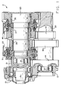
- FIG. 1 is an axial view, partly in cross section and partly in plan view, showing a manual transmission of the type to which the present invention is applicable.
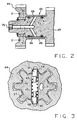
- FIG. 2 is a fragmentary view, similar to FIG. 1, illustrating the viscous damper portion according to the present invention.
- FIG. 3 in a transverse cross-section taken on line 3-3 of FIG. 2, but on a larger scale, illustrating the lost motion means associated with the viscous damper portion.
- FIG. 4 is a graph of rotational velocity in rpm., as a function of time, for the head gear and countershaft, utilizing the present invention.
- FIG. 5 is a graph of rotational torque in ft.-1b., as a function of time, for one of the driven gears, while it is in a disengaged mode.
- FIG. 1 is an axial view of a vehicle manual transmission generally designated 11.
- the transmission 11 includes several housing sections, all generally designated 13, the forward portion of which (left end in FIG. 1) receives an input shaft 15 which is rotatably supported relative to the housing 13 by means of a bearing set 17.
- the transmission input shaft 15 receives input drive torque from the vehicle engine crankshaft (not shown) in a manner well known to those skilled in the art.
- an input gear 19 Formed integrally with the input shaft 15 is an input gear 19, which is somewhat hollow, and has disposed therein a bearing set 21. Received within the bearing set 21, and rotatably supported thereby, is the forward end of the transmission output shaft 23, the rearward end of which is rotatably supported by the housing 13 within a set of bearings (not shown).
- the input shaft 15 and the output shaft 23 are coaxial, although that is not an essential feature of the present invention.
- a transmission countershaft 25 having its axis of rotation parallel to the axes of input shaft 15 and output shaft 23.
- the forward end of the countershaft 25 is rotatably supported within the housing 13 by means of a bearing set 27, while the rearward end of the countershaft 25 is similarly supported (not shown).
- rotatably disposed on the output shaft 23 is a first speed driven gear 31, a second speed driven gear 32 and a third speed driven gear 33.
- Each of the driven gears 31, 32 and 33 is mounted to be freely rotatable relative to the output shaft 23 by means of suitable sets of needle bearings 35, 37 and 39, respectively.
- the countershaft 25 includes a first speed drive gear 41, a second speed drive gear 42, and a third speed drive gear 43. As is shown in FIG. 1, the drive gears 41, 42 and 43 are in toothed engagement with, and operable to drive, the driven gears 31, 32, and 33. Preferably, the drive gears 41, 42 and 43 are formed integrally with the countershaft 25.
- a driven gear 44 Disposed toward the forward end of the countershaft 25 is a driven gear 44, which is more typically referred to as the "head gear".
- the head gear 44 would also be formed integrally with the countershaft 25, although it is now known from U.S. Patent No. US-A-4,677,868 for the head gear 44 to be separated from the countershaft 25, and to have the ability to rotate relative thereto by a small amount.
- a first and second speed synchronizer mechanism 47 Surrounding the output shaft 23, and disposed axially between the first and second speed driven gears 31 and 32 is a first and second speed synchronizer mechanism 47, adapted to be operated by a shift fork 49. Similarly, surrounding the output shaft 23, and axially disposed between the third speed driven gear 33 and the input gear 19 is a third and fourth speed synchronizer mechanism 51, adapted to be operated by a shift fork 53. As is well known to those skilled in the art, if the shift fork 49 is moved to a position which is operable to select first speed operation of the transmission, the synchronizer mechanism 47 is moved into frictional engagement with an adjacent frictional surface of the first speed driven gear 31.
- a splined coupling connects the synchronizer mechanism 47 (and thus, also the output shaft 23) to the driven gear 31. Because the synchronizer mechanism 47 is in splined engagement with the output shaft 23, such actuation of the mechanism 47 results in the first speed driven gear 31 being fixed to drive the output shaft 23. Therefore, when first speed operation has been selected by appropriate positioning of the shift fork 49, input torque is transmitted from the input shaft 15 through the input gear 19 to the head gear 44 which, in turn, transmits torque through the countershaft 25 and the first speed drive gear 41 to the first speed driven gear 31, and then to the output shaft 23 as described above.
- the synchronizer mechanism 47 is moved to the left in FIG. 1, to engage the second speed driven gear 32, and torque is transmitted as described above except that torque is then transmitted from the countershaft 25 and the second speed driven gear 32 to the output shaft 23.
- Positioning of the shift fork 53 to move the third and fourth speed synchronizer mechanism 51 to engage either the third speed driven gear 33 or the input gear 19 will result in operation of the transmission in either third speed or fourth speed, respectively.
- having the synchronizer mechanism 51 engage the input gear 19 for fourth speed operation results in a 1:1 relationship between the input shaft 15 and the output shaft 23.
- torque is being positively transmitted from the countershaft 25 through the peripheral teeth on the second speed drive gear 42 to the peripheral teeth on the second speed driven gear 32, to transmit input torque to the output shaft 23.
- the first speed drive gear 41 remains in toothed engagement with the first speed driven gear 31
- the third speed drive gear 43 remains in toothed engagement with the third speed driven gear 33.
- the only torque being transmitted from those drive gears to their respective driven gears is that required to overcome the friction of the needle bearings 35 and 39. Therefore, variations or oscillations in the speed of rotation of the input shaft 15 are transmitted to the countershaft 25 and to the first and third speed drive gears 41 and 43.
- each tooth on the drive gears 41 and 43 will tend to come out of contact with the adjacent tooth which is driving on the driven gear 31 and 33, respectively.
- the result of such periodic loss of, or tendency to lose, tooth contact is incipient gear rattle, i.e., a tooth on a drive gear comes out of engagement with the adjacent tooth on the driven gear and engages an adjacent, trailing tooth on the driven gear.
- FIG. 2 there is illustrated an axial cross-section through the countershaft 25 and head gear 44, illustrating a damper portion made in accordance with the present invention.
- the head gear 44 is formed separately from the countershaft 25 but is "fixed" to the countershaft by 25 by some form of lost motion means which is operable to permit a certain predetermined amount of relative rotation between the head gear 44 and the countershaft 25, but at the same time, is operable to transmit the full input torque from the head gear 44 to countershaft 25.
- the head gear 44 defines a set of internal splines 55, and in engagement therewith, the countershaft 25 defines a set of external splines 57, the splines 55 and 57 being sized relative to each other to provide for a predetermined amount of lost motion.
- the head gear 44 is able to rotate about 5 degrees relative to the countershaft 25.
- the splines are replaced by a centering mechanism.
- the head gear 44 defines a pair of angled cam surfaces 59, and in engagement with each of the cam surfaces 59 is a cam member 61.
- Each cam member 61 is biased toward its radially outermost position by a helical compression spring 63.
- each spline 55 is centered between the adjacent pair of splines 57.
- the purpose of this biasing and centering function, as it relates to the damper mechanism of the present invention, will be described subsequently.
- the term "centering" means merely that each of the splines 57 is out of engagement with each of the adjacent splines 59, but does not necessarily means that each spline 57 is evenly spaced between the adjacent splines 59.
- the head gear 44 includes a generally annular or cylindrical damper portion 65 extending to the right of the head gear 44, is preferably formed integrally therewith, and defines a generally cylindrical inner surface 66.
- the cylindrical damper portion 65 is disposed to surround a portion of the countershaft 25, between the head gear 44 and the third speed drive gear 43, which defines a generally cylindrical outer surface 26.
- the countershaft 25 defines a pair of annular grooves in which are disposed a pair of seals 67.
- the outer cylindrical surface of the countershaft 25, between the seals 67 cooperates with the inner cylindrical surface of the damper portion 66 to define a viscous shear space 69.
- a suitable viscous fluid such as a silicone oil
- shearing of the viscous fluid in the shear space 69 dampens oscillations or variations in the speed of the countershaft 25.
- the countershaft 25 defines an axial bore 71, which is in open communication with a pair of angled bores 73.
- the purpose of the bores 71 and 73 is to permit filling of the shear space 69 with viscous fluid prior to assembly of the transmission.
- a plug member 75 is threaded into the end of the axial bore 71, to retain the viscous fluid therein.
- the gear rattle problem occurs only when a relatively small amount of torque is being transmitted through the head gear to the countershaft. Therefore, in selecting the spring 63, it is necessary to know the approximate, maximum torque level at which incipient gear rattle occurs, for that particular transmission design. With this "maximum" torque level known, the spring 63 should be selected to satisfy the following two criteria:
- each graph represents the oscillations about the mean speed of 700 rpm.
- the graph labeled "44" illustrates the variations in the speed of rotation of the head gear 44, which are transmitted, without substantial change other than due to gear ratio, from input shaft 15. As mentioned previously, these variations were assumed to be ⁇ 16 rpm.
- the other graph is labeled "25" and represents the variations in the speed of rotation of the countershaft 25, downstream of the damper portion of the present invention.
- the mathematical simulation of the present invention determined that the variations in the speed of rotation of the countershaft would be approximately ⁇ 2 rpm., which is approximately one eighth of the variations in the input speed.
- FIG. 5 there is illustrated a graph of torque in ft.-1b., as a function of time, and the graph is labeled "31", because the graph represents the torque transmitted from the countershaft 25 to the first speed driven gear 31.
- the torque curve in FIG. 5 varies about a mean torque value (in the subject embodiment, 0,0092 Nm (0.0068 ft.-lbs.)) which represents the torque to overcome bearing friction, i.e., the friction in the needle bearings 35.
- the mathematical simulation indicates that the torque on the first speed driven gear 31 never drops below approximately 0,0083 Nm (0.0061 ft.-lbs.), which typically would be sufficient to avoid gear rattle. This is important because, as described previously, if the torque transmitted to any one of the "non-driving" driven gears approaches zero, the result will be incipient gear rattle. Therefore, it is an important aspect of the present invention that the substantial reduction in the variation in the rotational speed of the countershaft 25 will greatly minimize the variations in torque transmitted to the "non-driving" driven gear 31, thus keeping a minimum torque value far enough above zero to avoid gear rattle.
- the damping of the oscillations be accomplished by true viscous shear, rather than by forcing fluid through a dashpot or displacing fluid from between adjacent splines as in U.S. Patent No. US-A-4,677,868.
- dashpot damping or "pumping" fluid between adjacent splines it is critical to maintain tolerances very precisely, i.e., slight changes in certain dimensions can result in a substantial change in damping torque.
- true viscous shear damping is accordance with the present invention, it is relatively simple and inexpensive to maintain the necessary tolerances on the surfaces which define the viscous shear space 69.
Landscapes
- Engineering & Computer Science (AREA)
- General Engineering & Computer Science (AREA)
- Mechanical Engineering (AREA)
- Gears, Cams (AREA)
- General Details Of Gearings (AREA)
- Arrangement And Driving Of Transmission Devices (AREA)
- Structure Of Transmissions (AREA)
Claims (8)
- Manuelles Getriebe (11) mit einer Gehäuseanordnung (13), einer mit Bezug auf die Gehäuseanordnung drehbar abgestützten Antriebswelle (15), die Eingangs-Antriebsdrehmoment von einer Antriebsenergiequelle aufnehmen kann und eine Drehachse bestimmt; einer mit Bezug auf die Gehäuseanordnung drehbar abgestützten Abtriebswelle (23), die eine zu der Antriebswelle im wesentlichen parallele Drehachse bestimmt; einer mit Bezug auf die Gehäuseanordnung drehbar abgestützten Vorgelegewelle (25), die eine zu den Achsen der Antriebs- und der Abtriebswelle im wesentlichen parallele Drehachse aufweist; einem Antriebsrad (19), das mit einer Gruppe von am Umfang verteilten Zähnen versehen und mit der Antriebswelle drehfest verbunden ist; einem Kopfrad (44), das mit einer Gruppe von mit den Zähnen des Antriebsrades in Eingriff stehenden, am Umfang verteilten Zahnen versehen und mit der Vorgelegewelle drehfest verbunden ist, um Eingangs-Antriebsdrehmoment von der Antriebswelle auf die Vorgelegewelle zu übertragen; einem ersten treibenden Rad (41), das mit einer Gruppe von am Umfang verteilten Zähnen versehen und zur Aufnahme von Eingangs-Antriebsdrehmoment von der Vorgelegewelle befestigt ist; einem ersten getriebenen Rad (31), das mit einer Gruppe von mit den Zähnen des ersten treibenden Rades (41) in Eingriff stehenden, am Umfang verteilten Zähnen versehen ist; einer Anordnung (47), die zwischen einer ersten Stellung, in welcher mittels des ersten getriebenen Rades Antriebsdrehmoment von dem ersten treibenden Rad (41) auf die Abtriebswelle (23) übertragbar ist, und einer zweiten Stellung, in welcher das erste getriebene Rad mit Bezug auf die Abtriebswelle frei laufen kann, verschiebbar (49) ist; und einer dem Dämpfen der Übertragung von Torsionsschwingungen von dem Kopfrad (44) auf die Vorgelegewelle (25) dienenden Anordnung, die eine durch Zusammenwirken der Vorgelegewelle und des Kopfrades gebildete Totgangeinrichtung (55, 57) zum Begrenzen der Drehung des Kopfrades gegenüber der Vorgelegewelle aufweist,
dadurch gekennzeichnet, daß(a) eine Einrichtung (59, 61, 63) vorgesehen ist, welche die Vorgelegewelle in Richtung auf eine zentrierte Stellung mit Bezug auf das Kopfrad vorspannt, wobei sich die Vorgelegewelle zwischen ihren Dreh-Endstellungen mit Bezug auf das Kopfrad befindet; und(b) das Kopfrad und die Vorgelegewelle zusammen ein gesondert von der Totgangeinrichtung angeordnetes Viskositätsscherdämpferteil (65) bilden, das, wenn es mit viskosem Fluid (69) gefüllt ist, die relative Drehbewegung zwischen der Vorgelegewelle und dem Kopfrad dämpfen kann. - Manuelles Getriebe nach Anspruch 1, dadurch gekennzeichnet, daß die Totgangeinrichtung dadurch gebildet ist, daß das Kopfrad (44) eine Gruppe von Innenkeilzähnen (55) bildet und die Vorgelegewelle (25) eine Gruppe von Außenkeilzähnen (57) bildet, die mit den Innenkeilzähnen in relativ losem Keileingriff stehen.
- Manuelles Getriebe nach Anspruch 2, dadurch gekennzeichnet, daß die Innenkeilzähne (55) und die Außenkeilzähne (57) so ausgebildet sind, daß sie für eine Totgang-Drehbewegung zwischen dem Kopfrad (44) und der Vorgelegewelle (25) von etwa fünf Grad sorgen.
- Manuelles Getriebe nach Anspruch 1, dadurch gekennzeichnet, daß die Vorspanneinrichtung dadurch gebildet ist, daß das Kopfrad (44) oder die Vorgelegewelle (25) eine Nockenfläche (59) bilden und die Vorspanneinrichtung ferner einen Nocken (61) und Mittel (63) aufweist, welche den Nocken in Eingriff mit der Nockenfläche vorspannen.
- Manuelles Getriebe nach Anspruch 4, dadurch gekennzeichnet, daß die Vorspannmittel (63) eine ausreichende Vorspannkraft bereitstellen, um das Kopfrad (44) und die Vorgelegewelle (55) zwischen den Dreh-Endstellungen zu halten, wenn das von dem Kopfrad auf die Vorgelegewelle übertragene Eingangs-Antriebsdrehmoment ausreichend niedrig ist, um das Einsetzen von Zahnradrattern zu erlauben.
- Manuelles Getriebe nach Anspruch 4, dadurch gekennzeichnet, daß die Vorspannmittel (63) so gewählt sind, daß sie eine Drehbewegung der Vorgelegewelle (25) mit Bezug auf das Kopfrad (44) zulassen, wobei diese Drehbewegung im wesentlichen die gesamte verfügbare Bewegung zwischen den Dreh-Endstellungen ausmacht.
- Manuelles Getriebe nach Anspruch 1, dadurch gekennzeichnet, daß das Viskositätsdämpferteil (65) dadurch gebildet ist, daß die Vorgelegewelle (25) eine im wesentlichen zylindrische Außenfläche (26) bestimmt und das Kopfrad (44) eine im wesentlichen zylindrische Innenfläche (66) aufweist, wobei die Außenfläche (26) und die Innenfläche (66) zusammen einen Viskositätsscherraum (69) bestimmen.
- Manuelles Getriebe nach Anspruch 7, dadurch gekennzeichnet, daß die Vorgelegewelle (25) eine Durchlaßanordnung (71, 73) bildet, die für eine Verbindung von der Außenseite der Vorgelegewelle zu dem Viskositätsscherraum (69) sorgt, wobei die Durchlaßanordnung eine viskoses Fluid aufnehmende Speicheranordnung für den Viskositätsscherraum bilden kann.
Applications Claiming Priority (2)
| Application Number | Priority Date | Filing Date | Title |
|---|---|---|---|
| US07/250,208 US4873882A (en) | 1988-09-28 | 1988-09-28 | Manual transmission and gear rattle damper therefor |
| US250208 | 1999-02-15 |
Publications (2)
| Publication Number | Publication Date |
|---|---|
| EP0361686A1 EP0361686A1 (de) | 1990-04-04 |
| EP0361686B1 true EP0361686B1 (de) | 1993-03-31 |
Family
ID=22946756
Family Applications (1)
| Application Number | Title | Priority Date | Filing Date |
|---|---|---|---|
| EP89308733A Expired - Lifetime EP0361686B1 (de) | 1988-09-28 | 1989-08-30 | Handbedienter Antrieb und Anordnung zur Dämpfung des darin auftretenden Klappergeräusches |
Country Status (4)
| Country | Link |
|---|---|
| US (1) | US4873882A (de) |
| EP (1) | EP0361686B1 (de) |
| JP (1) | JPH02102949A (de) |
| DE (1) | DE68905737T2 (de) |
Families Citing this family (21)
| Publication number | Priority date | Publication date | Assignee | Title |
|---|---|---|---|---|
| FR2655115B1 (fr) * | 1989-11-30 | 1993-01-22 | Valeo | Amortisseur de vibrations, notamment pour vehicule automobile. |
| US5214975A (en) * | 1990-11-20 | 1993-06-01 | New Venture Gear, Inc. | Transmission vibration damping |
| DE4102280C2 (de) * | 1991-01-26 | 1993-11-11 | Daimler Benz Ag | Anordnung an einem Zahnrad zur Übertragung von Zahnkräften |
| DE4329404B4 (de) * | 1993-09-01 | 2004-01-08 | Volkswagen Ag | Zweiteiliges Zahnrad zur Reduzierung von Zahneingriffsgeräuschen |
| KR970075591A (ko) * | 1996-05-15 | 1997-12-10 | 박병재 | 자동변속기용 트랜스퍼 샤프트 |
| US6026698A (en) * | 1996-08-13 | 2000-02-22 | Weston; Bevan | Transmission and shift mechanism |
| US5816101A (en) * | 1996-08-13 | 1998-10-06 | Weston; Bevan | Transmission and shift mechanism |
| FR2830912B1 (fr) * | 2001-10-15 | 2003-12-19 | Nacam | Dispositif d'accouplement en rotation de deux arbres telescopiques |
| KR100461807B1 (ko) * | 2002-03-11 | 2004-12-14 | 현대자동차주식회사 | 변속기의 변속 조작 기구 |
| US20030183040A1 (en) * | 2002-03-27 | 2003-10-02 | Campen Richard A. | Shaft damping device |
| DE102004010270A1 (de) | 2004-03-03 | 2005-09-29 | Zf Friedrichshafen Ag | Einrichtung zum Verhindern des Taumelns der Summenräder in einem Getriebe mit zwei Vorgelegewellen |
| DE102004057126A1 (de) * | 2004-11-26 | 2006-06-08 | Zf Friedrichshafen Ag | Einrichtung zur Reduzierung der Axialbewegung der Hauptwellenräder bei einem Getriebe mit zumindest zwei Vorgelegewellen |
| US7338405B2 (en) * | 2005-04-05 | 2008-03-04 | Arvinmeritor Technology, Llc | Transmission with main shaft centering device |
| DE112008001898B4 (de) * | 2007-07-27 | 2018-07-19 | Schaeffler Technologies AG & Co. KG | Vorgelegegetriebe |
| DE102009014705B4 (de) * | 2009-03-27 | 2011-05-05 | Getrag Getriebe- Und Zahnradfabrik Hermann Hagenmeyer Gmbh & Cie Kg | Doppelkupplungsgetriebe |
| CA2799868A1 (en) * | 2011-12-29 | 2013-06-29 | Taiwan Fu Hsing Industrial Co., Ltd. | Transmission mechanism and electro-mechanical lock therewith |
| EP3832169A1 (de) * | 2012-10-31 | 2021-06-09 | Parker-Hannifin Corporation | Getriebesteuerungssystem zur vibrationsdämpfung |
| SE1350082A1 (sv) * | 2013-01-28 | 2014-07-29 | Scania Cv Ab | Växellåda och fordon som innefattar en sådan växellåda |
| US20140260716A1 (en) * | 2013-03-12 | 2014-09-18 | Steering Solutions Ip Holding Corporation | Stop teeth for a pinion and input shaft assembly |
| DE102013217035A1 (de) * | 2013-08-27 | 2015-03-05 | Volkswagen Aktiengesellschaft | Verfahren zum Zentrieren eines Zentrierteils und Rotationsbauteils |
| WO2020191128A1 (en) * | 2019-03-19 | 2020-09-24 | CK Industries, LLC | Pto coupler protector |
Family Cites Families (17)
| Publication number | Priority date | Publication date | Assignee | Title |
|---|---|---|---|---|
| US31154A (en) * | 1861-01-22 | Machine for reducing fibrous material | ||
| NL6885C (de) * | 1920-09-04 | |||
| US2696124A (en) * | 1952-04-22 | 1954-12-07 | Gen Motors Corp | Transmission antirattle gearing |
| US2812648A (en) * | 1955-06-28 | 1957-11-12 | Louis P Croset | Couplings for rotary members |
| FR1344080A (fr) * | 1962-01-20 | 1963-11-22 | Siemens Ag | Dispositif pour transmettre un mouvement ou pour amortir le déplacement d'éléments mobiles l'un par rapport à l'autre |
| US3263450A (en) * | 1964-02-13 | 1966-08-02 | Twin Disc Clutch Co | Damping connector for a power train |
| US3364768A (en) * | 1965-05-03 | 1968-01-23 | Chrysler Corp | Multiple speed power transmission mechanism |
| US3355909A (en) * | 1965-10-18 | 1967-12-05 | Borg Warner | Anti-rattle device for a torque transmitting mechanism |
| US3408830A (en) * | 1966-08-25 | 1968-11-05 | Eaton Yale & Towne | Torsion drive assembly |
| US3398594A (en) * | 1967-05-02 | 1968-08-27 | Gen Motors Corp | Spline antirattle device for countershaft transmission |
| USRE31154E (en) | 1977-05-16 | 1983-02-22 | Caterpillar Tractor Co. | Flexible drive |
| US4277956A (en) * | 1978-09-29 | 1981-07-14 | Lucas Industries Limited | Spline drive arrangement |
| FR2548303B1 (fr) * | 1983-06-30 | 1985-10-25 | Dba | Perfectionnements apportes aux freins multidisques |
| DE3516104A1 (de) * | 1985-05-04 | 1986-11-06 | Goetze Ag, 5093 Burscheid | Schwingungstilger mit hydraulischer daempfung |
| JPH045778Y2 (de) * | 1985-07-17 | 1992-02-18 | ||
| US4677868A (en) * | 1986-04-10 | 1987-07-07 | Chrysler Motors Corporation | Transmission vibration viscous damper |
| US4772245A (en) * | 1987-07-09 | 1988-09-20 | Sundstrand Corportion | Torque transmitting elastomeric shaft coupling with spline backup |
-
1988
- 1988-09-28 US US07/250,208 patent/US4873882A/en not_active Expired - Fee Related
-
1989
- 1989-08-30 DE DE8989308733T patent/DE68905737T2/de not_active Expired - Fee Related
- 1989-08-30 EP EP89308733A patent/EP0361686B1/de not_active Expired - Lifetime
- 1989-09-28 JP JP1253713A patent/JPH02102949A/ja active Pending
Also Published As
| Publication number | Publication date |
|---|---|
| DE68905737T2 (de) | 1993-07-08 |
| JPH02102949A (ja) | 1990-04-16 |
| EP0361686A1 (de) | 1990-04-04 |
| US4873882A (en) | 1989-10-17 |
| DE68905737D1 (de) | 1993-05-06 |
Similar Documents
| Publication | Publication Date | Title |
|---|---|---|
| EP0361686B1 (de) | Handbedienter Antrieb und Anordnung zur Dämpfung des darin auftretenden Klappergeräusches | |
| US6062360A (en) | Synchronizer for a gear shift mechanism for a marine propulsion system | |
| US5366421A (en) | Differential apparatus | |
| US5033323A (en) | Gear rattle damper for countershaft transmissions | |
| US7311633B2 (en) | Vehicular four-wheel drive unit | |
| US4679679A (en) | Clutch driven plate assembly with anti-backlash damping | |
| US7413067B2 (en) | Dog clutch | |
| US7163095B2 (en) | Clutch assembly with vibration damper | |
| US11592094B2 (en) | Differential having an overrunning clutch with inertial compensation tuning | |
| US4754659A (en) | Quill shaft input cluster gear for manual transmission | |
| US5697847A (en) | Torsion bar drive coupling | |
| CN1070994A (zh) | 液力滑体联轴器 | |
| US4674347A (en) | Torsional vibration absorbing system for vehicular power transmission | |
| US4322985A (en) | Engine starter with an overrunning clutch device | |
| EP0393285B1 (de) | Kupplung für Kraftübertragung | |
| JPS62237136A (ja) | ねじれ減衰機構 | |
| JPH05126167A (ja) | 伝動装置 | |
| JP4743808B2 (ja) | コンバインのトランスミッション | |
| JP3201988B2 (ja) | 動力伝達機構 | |
| JP2589428Y2 (ja) | 2方向差動クラッチの給油構造 | |
| JPH0716105Y2 (ja) | 変速機の同期噛合装置 | |
| EP4234977B1 (de) | Kraftübertragungsvorrichtung | |
| EP0745783A1 (de) | Viskositätsdämpfer mit Scherungsplatte für verbesserte Strömung | |
| SU1060509A1 (ru) | Автоматическа коробка передач | |
| US6443284B1 (en) | Torsion bar isolator |
Legal Events
| Date | Code | Title | Description |
|---|---|---|---|
| PUAI | Public reference made under article 153(3) epc to a published international application that has entered the european phase |
Free format text: ORIGINAL CODE: 0009012 |
|
| AK | Designated contracting states |
Kind code of ref document: A1 Designated state(s): DE FR GB IT |
|
| 17P | Request for examination filed |
Effective date: 19901001 |
|
| 17Q | First examination report despatched |
Effective date: 19920521 |
|
| GRAA | (expected) grant |
Free format text: ORIGINAL CODE: 0009210 |
|
| AK | Designated contracting states |
Kind code of ref document: B1 Designated state(s): DE FR GB IT |
|
| ITF | It: translation for a ep patent filed | ||
| REF | Corresponds to: |
Ref document number: 68905737 Country of ref document: DE Date of ref document: 19930506 |
|
| ET | Fr: translation filed | ||
| PLBE | No opposition filed within time limit |
Free format text: ORIGINAL CODE: 0009261 |
|
| STAA | Information on the status of an ep patent application or granted ep patent |
Free format text: STATUS: NO OPPOSITION FILED WITHIN TIME LIMIT |
|
| 26N | No opposition filed | ||
| PGFP | Annual fee paid to national office [announced via postgrant information from national office to epo] |
Ref country code: GB Payment date: 19970702 Year of fee payment: 9 |
|
| PGFP | Annual fee paid to national office [announced via postgrant information from national office to epo] |
Ref country code: FR Payment date: 19970812 Year of fee payment: 9 |
|
| PGFP | Annual fee paid to national office [announced via postgrant information from national office to epo] |
Ref country code: DE Payment date: 19970827 Year of fee payment: 9 |
|
| PG25 | Lapsed in a contracting state [announced via postgrant information from national office to epo] |
Ref country code: GB Free format text: LAPSE BECAUSE OF NON-PAYMENT OF DUE FEES Effective date: 19980830 |
|
| GBPC | Gb: european patent ceased through non-payment of renewal fee |
Effective date: 19980830 |
|
| PG25 | Lapsed in a contracting state [announced via postgrant information from national office to epo] |
Ref country code: FR Free format text: LAPSE BECAUSE OF NON-PAYMENT OF DUE FEES Effective date: 19990430 |
|
| PG25 | Lapsed in a contracting state [announced via postgrant information from national office to epo] |
Ref country code: DE Free format text: LAPSE BECAUSE OF NON-PAYMENT OF DUE FEES Effective date: 19990601 |
|
| REG | Reference to a national code |
Ref country code: FR Ref legal event code: ST |
|
| PG25 | Lapsed in a contracting state [announced via postgrant information from national office to epo] |
Ref country code: IT Free format text: LAPSE BECAUSE OF NON-PAYMENT OF DUE FEES;WARNING: LAPSES OF ITALIAN PATENTS WITH EFFECTIVE DATE BEFORE 2007 MAY HAVE OCCURRED AT ANY TIME BEFORE 2007. THE CORRECT EFFECTIVE DATE MAY BE DIFFERENT FROM THE ONE RECORDED. Effective date: 20050830 |