EP0361689B1 - Messsonde für elektrische Schaltungen - Google Patents
Messsonde für elektrische Schaltungen Download PDFInfo
- Publication number
- EP0361689B1 EP0361689B1 EP89308768A EP89308768A EP0361689B1 EP 0361689 B1 EP0361689 B1 EP 0361689B1 EP 89308768 A EP89308768 A EP 89308768A EP 89308768 A EP89308768 A EP 89308768A EP 0361689 B1 EP0361689 B1 EP 0361689B1
- Authority
- EP
- European Patent Office
- Prior art keywords
- probe
- tubular housing
- plunger
- open end
- inner portion
- Prior art date
- Legal status (The legal status is an assumption and is not a legal conclusion. Google has not performed a legal analysis and makes no representation as to the accuracy of the status listed.)
- Expired - Lifetime
Links
- 239000000523 sample Substances 0.000 title claims abstract description 99
- 238000012360 testing method Methods 0.000 title claims abstract description 31
- 230000036316 preload Effects 0.000 claims description 5
- 238000000034 method Methods 0.000 claims description 4
- 239000004020 conductor Substances 0.000 claims description 3
- 238000003780 insertion Methods 0.000 claims description 3
- 230000037431 insertion Effects 0.000 claims description 3
- 230000006835 compression Effects 0.000 claims 7
- 238000007906 compression Methods 0.000 claims 7
- 238000005096 rolling process Methods 0.000 claims 2
- 238000013461 design Methods 0.000 description 13
- 239000002245 particle Substances 0.000 description 6
- 238000007790 scraping Methods 0.000 description 6
- 230000004048 modification Effects 0.000 description 3
- 238000012986 modification Methods 0.000 description 3
- 230000009471 action Effects 0.000 description 2
- 230000000994 depressogenic effect Effects 0.000 description 2
- 230000000717 retained effect Effects 0.000 description 2
- 229910000679 solder Inorganic materials 0.000 description 2
- 230000015572 biosynthetic process Effects 0.000 description 1
- 230000008859 change Effects 0.000 description 1
- 238000004140 cleaning Methods 0.000 description 1
- ZPUCINDJVBIVPJ-LJISPDSOSA-N cocaine Chemical compound O([C@H]1C[C@@H]2CC[C@@H](N2C)[C@H]1C(=O)OC)C(=O)C1=CC=CC=C1 ZPUCINDJVBIVPJ-LJISPDSOSA-N 0.000 description 1
- 230000002301 combined effect Effects 0.000 description 1
- 239000000356 contaminant Substances 0.000 description 1
- 238000002788 crimping Methods 0.000 description 1
- 230000006866 deterioration Effects 0.000 description 1
- 230000004907 flux Effects 0.000 description 1
- 238000005304 joining Methods 0.000 description 1
- 238000004519 manufacturing process Methods 0.000 description 1
- 230000004044 response Effects 0.000 description 1
Images

Classifications
-
- G—PHYSICS
- G01—MEASURING; TESTING
- G01R—MEASURING ELECTRIC VARIABLES; MEASURING MAGNETIC VARIABLES
- G01R1/00—Details of instruments or arrangements of the types included in groups G01R5/00 - G01R13/00 and G01R31/00
- G01R1/02—General constructional details
- G01R1/06—Measuring leads; Measuring probes
- G01R1/067—Measuring probes
- G01R1/06711—Probe needles; Cantilever beams; "Bump" contacts; Replaceable probe pins
- G01R1/06716—Elastic
- G01R1/06722—Spring-loaded
Definitions
- the present invention relates to probes used for testing electrical circuits and, more particularly, to a probe for providing electrical contact to electrical circuits during the testing thereof comprising, a tubular housing having an open end and a generally closed end having a small cleaning hole therethrough; a probe plunger disposed in the tubular housing, the probe plunger comprising a cylindrical inner portion being a slide fit within the tubular housing and a cylindrical outer portion of a diameter smaller than the inner portion and forming a shoulder with the inner portion at a point of meeting; a longitudinally compressed bias spring disposed between the closed end of the tubular housing and the inner portion of the probe plunger for urging the probe plunger to an extended position; and, a cylindrical retaining and sliding bearing region formed adjacent the open end of the tubular housing and having the outer portion of the plunger passing therethrough, the retaining and sliding bearing region having an internal diameter which is a slide fit to the outside diameter of the outer portion.
- Test probes are used in groups of hundreds or thousands for contacting a printed circuit board under test.
- Computer-based testers are used to supply signals and analyze outputs from the board under test.
- One hundred percent production testing of computer boards and other electronic equipment board is the typical industry standard.
- the probes employed must be very reliable.
- One is the failure of the probe's tip to pierce the flux or oxide films on the solder-coated pads of the circuit board. This problem typically applies to in-circuit testing after components are assembled to the board and the board itself has been wave soldered, or the like, to affix the components to the board.
- Another major point of probe failure is a result of internal wear of the probe itself, which generates contaminating particulates. These particulates, in turn, prevent good electrical contact between the probe plunger and the tubular housing.
- This wear can be caused by spring fatigue (which allows sharp broken coils to scrape particles from the tubular housing's internal surfaces) or as a result of probe side loading.
- Side loading occurs if probe points engage the sloped sides of solder lumps or bent component leads, or if single pointed probes enter misaligned holes in test boards.
- the probe generally indicated as 10 in Figure 1 represents an early design in the art. It was manufactured in strokes up to 4mm for 2.5 mm mounting centers.
- the probe plunger 12 comprises an inner portion 14 which has a diameter sized to be slide fit in the tubular housing 16.
- An outer portion 18 extends outward concentrically from the inner portion 14.
- the outer portion 18 is of a smaller diameter than the inner portion 14 thereby forming a shoulder 20 at their point of joining.
- the probe plunger 12 is retained in the tubular housing 16 by crimping the housing around the outer portion 18. As depicted in Figure 2, the tolerances must be kept quite close to prevent problems. If the tolerance between the outside diameter of the inner portion 14 is not very close with respect to the inner diameter of the tubular housing 16, the plunger 12 scrapes the sharp edge of the crimp, as indicated by the arrow 22, generating wear particles which rapidly degrade the performance of the probe 10.
- the plunger 12 can bind in the housing 16, causing probe failure.
- excessive side loading can cause rubbing and wear regardless of the tolerances held during assembly.
- breaking of the outward bias spring 26 can cause sharp edges that produce undesired and damaging particles through scraping.
- the probe plunger 12′ of this design has an inner portion 14′ and an outer portion 18′ of the same diameter separated by a middle portion 30 of reduced diameter.
- the plunger 12′ is retained within the housing 16 by a crimp 32 disposed along the length of the housing 16 at a point which will intercept the shoulder 34 formed by the junction of the inner portion 14′ and the middle portion 30.
- the plunger 12′ is guided longitudinally within the housing 16 by the combined effect of the outer portion 18′ and inner portion 14′ sliding within the tubular housing 16.
- the outer portion 18′ must fit within the housing 16 a sufficient distance following insertion at one station so as to remain stable during movement to the next station when the plunger can be depressed to pre-load the spring 26 and the crimp 32 made in the housing 16. This forces the spring 26 to be shorter than would be desirable. In order to get the required piercing force at the tip, the spring 26 must, therefore, be quite stiff. This results in a higher propensity to breakage of the spring 26.
- the prior art probe 10′ of Figure 3 typically provides full stroke spring life below 100,000 cycles.
- Document EP-A-0257832 discloses a telescoping pin probe including a tubular member one end of which houses a fixed pin, said tubular member being reduced in diameter in order to fix said pin.
- test probe for use in electrical component test beds, and the like, which has a design which resists scraping action between the components which can produce probe-deteriorating particles.
- a probe according to the invention is defined in Claim 1.
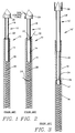
- Figure 1 is a cutaway elevation drawing of a prior art test probe in a first embodiment.
- Figure 2 is a drawing of the probe of Figure 1 illustrating some of the problems associated therewith.
- Figure 3 is a cutaway elevation drawing of a prior art test probe in a second embodiment.
- Figure 4 is a cutaway elevation drawing of a test probe according to the present invention.
- Figure 5 is a partial, cutaway drawing of the probe of Figure 4 showing the probe plunger being inserted into the tubular housing during assembly to pre-load the spring.
- Figure 6 is a partial, cutaway drawing of the probe of the present invention following the insertion step of Figure 5 and showing the probe plunger inserted into the tubular housing with the spring pre-loaded and prior to forming the retaining end thereon.
- Figure 7 is a partial, cutaway drawing of the probe of the present invention during assembly following the position of Figure 6 showing the manner in which the probe plunger is held captive in the tubular housing with the spring pre-loaded by the forming of a retaining and sliding bearing region on the end of the tubular housing.
- probe 10 ⁇ is a modification of the early prior art probe 10 described herein previously with respect to Figures 1 and 2. Like the prior art probes which it replaces, the components are all of electrically conductive materials. It should be pointed out immediately, however, that the modifications to the prior art probe of Figures 1 and 2 that result in the present invention also produced unexpected benefits which were not apparent or obvious.
- the probe 10 ⁇ of the present invention has increased the stroke length within the industry standard shut height from 0,407 cm (0.16 inch) to 0,636 cm (0.25 inch) which was the stroke length increase achieved by the changeover to the probe 10′ of Figure 3.
- the springs within the probe 10" of the present invention achieved a minimum cycle life of 3.6 million (3,600,000) deflections at full stroke. This life is stated as "minimum” because, as of this time, no springs have been broken in one hundred test probes tested to that level.
- a separate test of sixty probes also manufactured in accordance with the present invention resulted in probes tested having a resistance below 30 milliohms with 14 milliohms being a typical resistance.
- No known commercial probes according to the prior art are known to achieve such characteristics.
- the probe can be produced in a miniaturized version which is equally reliable; yet, capable of mounting on 1,27 mm spacing. The benefits relative to testing of electronic circuit boards which also are becoming increasingly miniaturized are readily apparent.
- the tubular housing 16 is of extended length to hold the extended length spring 26 that is possible with the configuration and method of assembly. As compared to the prior art design of Figure 3, this invention provides 50% more shut height for the spring.
- the probe plunger 12 is of substantially the same design as the plunger 12 of the prior art probe 10; however, the outer portion 18 is longer and the inner end 36 of the inner portion 14 is angled as shown to create a sideward force that provides improved electrical contact from the housing 16 through to the plunger 12 in a manner known in the art.
- the spring 26 is first inserted followed by the inner portion 14. Contrary to the design of probe 10′ of Figure 3, the plunger 12 is stable with a relatively short engagement. Thus, the spring in this design can not only be longer; but, can be pre-loaded much more than the prior art designs. This additional pre-loading provides more uniform plunger force in the operating range and, additionally, the longer spring fatigue life that provides the above-reported vast increase in cycle life without spring breakage. With the plunger 12 inserted as shown in Figure 5, it is depressed as shown in Figure 6 to pre-load the spring 26 and position the shoulder 20 away from the open end 38 of the housing 16.
- the area of the housing 16 between the shoulder 20 and the open end 38 is then closed by swaging, or the like, to form a reduced diameter retaining and sliding bearing region 40.
- this design offers extended low electrical resistance life as well as excellent tolerance to side loading forces. Since the area of contact is an extended one with no exposed corners or edges of the bearing surface of region 40 or the tubular housing 16 in contact with the probe plunger 12 (as compared to the prior art probe 10) there is no potential for the edge scraping produced by that design.
- the probe of the present invention has met its stated objectives by providing a probe that has increased spring length, increased spring loading, increased spring life, and no potential for particle-producing scraping action between any of the components, even in the presence of side loading forces, all with the same stroke length and within the same shut height space as the prior art probes with which it is interchangeably replaceable.
Landscapes
- Physics & Mathematics (AREA)
- General Physics & Mathematics (AREA)
- Measuring Leads Or Probes (AREA)
Claims (4)
- Sondeneinheit, welche elektrischen Kontakt zu elektrischen Schaltungen herstellt, während diese gemessen werden, von der Art, daß sie einen Sondentauchkolben (12), der in einem röhrenförmigen Gehäuse (16) angeordnet ist, aufweist und durch ein offenes Ende (38) von besagtem röhrenförmigen Gehäuse durch die Kraft einer vorgespannten Druckfeder (26), welche sich innerhalb des röhrenförmigen Gehäuses befindet, nach außen getrieben wird, wobei besagter Sondentauchkolben einen zylindrischen inneren Teil (14), welcher einen Gleitsitz und einen elektrischen Kontakt mit besagtem röhrenförmigen Gehäuse herstellt, und einen zylindrischen äußeren Teil (18) von kleinerem Durchmesser als der innere Teil aufweist und an der Verbindungsstelle zwischen den Teilen einen Absatz zu besagtem inneren Teil ausbildet, wobei das röhrenförmige Gehäuse aus einem deformierbaren, elektrisch leitenden Material besteht, und wobei die Sonde zusammengebaut wird, indem der innere Teil (14) des Sondentauchkolbens (12) in das offene Ende von besagtem röhrenförmigen Gehäuse eingesetzt wird, wobei das offene Ende folglich deformiert wird, um den Absatz innerhalb des Gehäuses zurückzuhalten,
dadurch gekennzeichnet, daß
ein Teil der Länge von besagtem röhrenförmigen Gehäuse von seinem offenen Ende (38) her im Umfang gegen den äußeren Teil (18) des Tauchkolbens gedrückt wird, um eine langgezogene zylindrische Rückhalte- und Gleitlagerfläche (40) zu erzeugen, welche mit besagtem äußeren Teil (18) eine Gleitpassung mit geringem Spiel aufweist, wodurch die Länge der Kompressionsfeder und somit ihre Fähigkeit, den Sondentauchkolben vorzuspannen, maximiert wird, und dadurch, daß das innere Ende (36) des inneren Teiles der Tauchkolbensonde mit einer gewinkelten Oberfläche ausgebildet ist, wodurch Druck auf besagte Oberfläche ausgeübt wird, indem die Druckfeder das innere Ende in Kontakt mit den röhrenförmigen Gehäuse zwingt, um einen guten elektrischen Kontakt sicherzustellen. - Meßsonde nach Anspruch 1,
dadurch gekennzeichnet, daß
die Kompression von besagtem offenen Ende (38) des röhrenförmigen Gehäuses (16) durch Rundkneten oder Rollen erreicht wird. - Verfahren zum Zusammenbau einer Meßsondeneinheit zum Herstellen von elektrischen Kontakt zu elektrischen Schaltungen während des Testens von diesen, der Art, daß sie einen Sondentauchkolben (12) aufweist, der in einem röhrenförmigen Gehäuse (16) angeordnet ist, und der durch ein offenes Ende (38) von besagtem röhrenförmigen Gehäuse durch die Kraft einer vorgespannten Druckfeder (26) nach außen gezwängt wird, welche sich innerhalb des röhrenförmigen Gehäuses befindet, wobei vorgesehen ist:- Formen des röhrenförmigen Gehäuses (16) mit einem offenen Ende (38) aus einem deformierbaren, elektrisch leitenden Material;- Formen des Sondentauchkolbens (12) mit einem zylindrischen inneren Teil (14), daß er innerhalb besagten röhrenförmigen Gehäuses eine Gleitpassung aufweist, und Formen eines zylindrischen äußeren Teiles (18) mit einem Durchmesser, der kleiner ist als der innere Teil, daß er einen Absatz (20) zu dem inneren Teil an der Verbindung der Teile aufweist;- Einsetzen der Druckfeder (26) und des inneren Teiles (14) des Sondentauchkolbens (12) durch das offene Ende (38) in das röhrenförmige Gehäuse (16);- Deformieren des offenen Endes (38), um den Absatz innerhalb des Gehäuses zurückzuhalten;gekennzeichnet, durch
Komprimieren eines Teiles der Länge des röhrenförmigen Gehäuses von besagtem offenen Ende (38) aus über den Umfang des äußeren Teiles (18) des Tauchkolbens, nachdem der Sondentauchkolben in das röhrenförmige Gehäuse eingesetzt wurde, um eine langgezogene, zurückhaltende und gleitende Lagerfläche (40) zu erzeugen, welche mit dem äußeren Teil eine Gleitpassung mit geringem Spiel bildet, wobei die Länge der Druckfeder und so ihre Fähigkeit, den Meßsondentauchkolben vorzuspannen, maximiert wird, und wobei das innere Ende (36) vom inneren Teil des Sondentauchkolbens (12) vor dem Einsetzen in das röhrenförmige Gehäuse (16) geformt wurde, um so eine winklige Oberfläche aufzuweisen. - Verfahren nach Anspruch 3,
dadurch gekennzeichnet, daß
die langgezogene, zurückhaltende und gleitende Lagerfläche durch Rundkneten oder Rollen erzielt wird.
Applications Claiming Priority (2)
| Application Number | Priority Date | Filing Date | Title |
|---|---|---|---|
| US07242786 US4885533B1 (en) | 1988-09-09 | 1988-09-09 | Electrical circuit test probe having an elongate cylindrical retaining and sliding bearing region |
| US242786 | 1988-09-09 |
Publications (2)
| Publication Number | Publication Date |
|---|---|
| EP0361689A1 EP0361689A1 (de) | 1990-04-04 |
| EP0361689B1 true EP0361689B1 (de) | 1995-07-19 |
Family
ID=22916179
Family Applications (1)
| Application Number | Title | Priority Date | Filing Date |
|---|---|---|---|
| EP89308768A Expired - Lifetime EP0361689B1 (de) | 1988-09-09 | 1989-08-30 | Messsonde für elektrische Schaltungen |
Country Status (8)
| Country | Link |
|---|---|
| US (1) | US4885533B1 (de) |
| EP (1) | EP0361689B1 (de) |
| JP (2) | JP3266244B2 (de) |
| AT (1) | ATE125365T1 (de) |
| CA (1) | CA1309464C (de) |
| DE (1) | DE68923517T2 (de) |
| ES (1) | ES2074466T3 (de) |
| IE (1) | IE67528B1 (de) |
Families Citing this family (33)
| Publication number | Priority date | Publication date | Assignee | Title |
|---|---|---|---|---|
| US5982187A (en) * | 1993-07-01 | 1999-11-09 | Alphatest Corporation | Resilient connector having a tubular spring |
| JP3659662B2 (ja) * | 1993-12-24 | 2005-06-15 | 株式会社デンソー | プローブコンタクト |
| US5484306A (en) * | 1994-10-20 | 1996-01-16 | Interconnect Devices Inc. | Quick-connect terminal and receptacle |
| DE29519413U1 (de) * | 1995-12-07 | 1996-01-25 | TSK Prüfsysteme GmbH, 32457 Porta Westfalica | Prüfstift |
| US6051982A (en) * | 1996-08-02 | 2000-04-18 | International Business Machines Corporation | Electronic component test apparatus with rotational probe and conductive spaced apart means |
| US5804984A (en) * | 1996-08-02 | 1998-09-08 | International Business Machines Corporation | Electronic component test apparatus with rotational probe |
| US5801544A (en) * | 1997-01-16 | 1998-09-01 | Delaware Capital Formation, Inc. | Spring probe and method for biasing |
| US6104205A (en) * | 1998-02-26 | 2000-08-15 | Interconnect Devices, Inc. | Probe with tab retainer |
| US6243655B1 (en) * | 1998-08-05 | 2001-06-05 | International Business Machines Corporation | Circuit trace probe and method |
| US6172514B1 (en) * | 1999-03-12 | 2001-01-09 | Lucent Technologies Inc. | Test probe retainer |
| US6570399B2 (en) * | 2000-05-18 | 2003-05-27 | Qa Technology Company, Inc. | Test probe and separable mating connector assembly |
| US6424166B1 (en) * | 2000-07-14 | 2002-07-23 | David W. Henry | Probe and test socket assembly |
| US6876530B2 (en) * | 2001-01-12 | 2005-04-05 | Qa Technology Company, Inc. | Test probe and connector |
| ATE371196T1 (de) * | 2002-03-05 | 2007-09-15 | Rika Denshi America Inc | Vorrichtung für eine schnittstelle zwischen elektronischen gehäusen und testgeräten |
| TWI233489B (en) * | 2003-01-21 | 2005-06-01 | Leeno Ind Inc | Contact apparatus and test PCB including the contact apparatus used for testing microwave device, and manufacturing method of the test PCB |
| US7109732B2 (en) * | 2003-07-31 | 2006-09-19 | Endicott Interconnect Technologies, Inc. | Electronic component test apparatus |
| JP2005116724A (ja) * | 2003-10-07 | 2005-04-28 | Renesas Technology Corp | 半導体装置及びその製造方法 |
| US20050184747A1 (en) * | 2004-02-19 | 2005-08-25 | Sanders David L. | Spring plunger probe |
| US7259576B2 (en) * | 2005-03-14 | 2007-08-21 | Agilent Technologies, Inc. | Method and apparatus for a twisting fixture probe for probing test access point structures |
| US7248065B2 (en) * | 2005-04-22 | 2007-07-24 | Hewlett-Packard Development Company, L.P. | Arcuate blade probe |
| US7453278B2 (en) * | 2005-04-22 | 2008-11-18 | Hewlett-Packard Development Company, L.P. | Methods of using a blade probe for probing a node of a circuit |
| US8253430B2 (en) * | 2005-04-22 | 2012-08-28 | Hewlett-Packard Development Company | Circuit board testing using a probe |
| US7154286B1 (en) * | 2005-06-30 | 2006-12-26 | Interconnect Devices, Inc. | Dual tapered spring probe |
| US20070084903A1 (en) * | 2005-10-13 | 2007-04-19 | Alexander Leon | Pronged fork probe tip |
| US7279912B2 (en) * | 2005-10-13 | 2007-10-09 | Hewlett-Packard Development Company, L.P. | Dual arcuate blade probe tip |
| ITGE20060052A1 (it) * | 2006-05-05 | 2007-11-06 | Hypertac S P A | Contatto per connessioni elettriche od elettroniche. |
| US7616019B2 (en) * | 2006-05-08 | 2009-11-10 | Aspen Test Engineering, Inc. | Low profile electronic assembly test fixtures |
| US20080143367A1 (en) * | 2006-12-14 | 2008-06-19 | Scott Chabineau-Lovgren | Compliant electrical contact having maximized the internal spring volume |
| US7549884B2 (en) * | 2007-01-29 | 2009-06-23 | Samtec, Inc. | Probe having a field-replaceable tip |
| US8410948B2 (en) * | 2008-05-12 | 2013-04-02 | John Vander Horst | Recreational vehicle holding tank sensor probe |
| US8506307B2 (en) | 2010-12-02 | 2013-08-13 | Interconnect Devices, Inc. | Electrical connector with embedded shell layer |
| USD699607S1 (en) * | 2012-03-01 | 2014-02-18 | Yamaichi Electronics Co., Ltd. | Contact probe |
| JP6841518B2 (ja) * | 2019-02-15 | 2021-03-10 | 株式会社サンケイエンジニアリング | プローブユニット |
Citations (3)
| Publication number | Priority date | Publication date | Assignee | Title |
|---|---|---|---|---|
| US3182257A (en) * | 1961-05-18 | 1965-05-04 | Motorola Inc | Electronic test probe |
| DE3045882A1 (de) * | 1980-12-05 | 1982-07-08 | Ingun Prüfmittelbau GmbH & Co KG Elektronik, 7750 Konstanz | Vorrichtung zum pruefen einer elektronischen leiterplatte oder einer entsprechenden elektronischen baugruppe mit kontaktstiften sowie kontaktstift dafuer |
| EP0257832A2 (de) * | 1986-08-01 | 1988-03-02 | Tektronix, Inc. | Teleskopartige Nadelsonde |
Family Cites Families (5)
| Publication number | Priority date | Publication date | Assignee | Title |
|---|---|---|---|---|
| US4397519A (en) * | 1981-05-12 | 1983-08-09 | Pylon Company, Inc. | Electrical contact construction |
| US4461993A (en) * | 1981-09-21 | 1984-07-24 | Everett/Charles, Inc. | Low resistance electrical spring probe |
| US4504780A (en) * | 1982-08-25 | 1985-03-12 | Marsella John R | Test probe |
| DE3410093A1 (de) * | 1984-03-20 | 1985-10-03 | Feinmetall Gmbh, 7033 Herrenberg | Federkontaktstift und verfahren zu seiner herstellung |
| US4659987A (en) * | 1985-03-25 | 1987-04-21 | Qa Technology Company | Electrical circuit test probe and connector |
-
1988
- 1988-09-09 US US07242786 patent/US4885533B1/en not_active Expired - Lifetime
-
1989
- 1989-08-28 IE IE276289A patent/IE67528B1/en not_active IP Right Cessation
- 1989-08-29 CA CA000609738A patent/CA1309464C/en not_active Expired - Lifetime
- 1989-08-30 AT AT89308768T patent/ATE125365T1/de not_active IP Right Cessation
- 1989-08-30 DE DE68923517T patent/DE68923517T2/de not_active Expired - Fee Related
- 1989-08-30 EP EP89308768A patent/EP0361689B1/de not_active Expired - Lifetime
- 1989-08-30 ES ES89308768T patent/ES2074466T3/es not_active Expired - Lifetime
- 1989-09-08 JP JP23177989A patent/JP3266244B2/ja not_active Expired - Fee Related
-
2001
- 2001-10-11 JP JP2001313872A patent/JP2002162414A/ja active Pending
Patent Citations (3)
| Publication number | Priority date | Publication date | Assignee | Title |
|---|---|---|---|---|
| US3182257A (en) * | 1961-05-18 | 1965-05-04 | Motorola Inc | Electronic test probe |
| DE3045882A1 (de) * | 1980-12-05 | 1982-07-08 | Ingun Prüfmittelbau GmbH & Co KG Elektronik, 7750 Konstanz | Vorrichtung zum pruefen einer elektronischen leiterplatte oder einer entsprechenden elektronischen baugruppe mit kontaktstiften sowie kontaktstift dafuer |
| EP0257832A2 (de) * | 1986-08-01 | 1988-03-02 | Tektronix, Inc. | Teleskopartige Nadelsonde |
Non-Patent Citations (1)
| Title |
|---|
| Jahrbuch der deutschen Gesellschaft für Chronometrie e.V., Vo. 30, 1979, p. 272 * |
Also Published As
| Publication number | Publication date |
|---|---|
| DE68923517D1 (de) | 1995-08-24 |
| CA1309464C (en) | 1992-10-27 |
| US4885533A (en) | 1989-12-05 |
| JPH02108973A (ja) | 1990-04-20 |
| DE68923517T2 (de) | 1996-01-04 |
| US4885533B1 (en) | 1998-11-03 |
| IE892762L (en) | 1990-03-09 |
| JP2002162414A (ja) | 2002-06-07 |
| IE67528B1 (en) | 1996-04-03 |
| JP3266244B2 (ja) | 2002-03-18 |
| ATE125365T1 (de) | 1995-08-15 |
| ES2074466T3 (es) | 1995-09-16 |
| EP0361689A1 (de) | 1990-04-04 |
Similar Documents
| Publication | Publication Date | Title |
|---|---|---|
| EP0361689B1 (de) | Messsonde für elektrische Schaltungen | |
| DE69711083T2 (de) | Kontaktstift für prüfzwecke | |
| DE60118465T2 (de) | Sonde und Testfassungsanordnung | |
| US4701702A (en) | Contact pin having a spring under tension | |
| CN112858744A (zh) | 探针 | |
| EP2646839A1 (de) | Passender elektrischer kontakt und anordnung damit | |
| CN101884139A (zh) | 顺应性电触头和组件 | |
| DE19941129A1 (de) | Meßfassung | |
| EP0030407A1 (de) | Elektrischer Tastkopf zur Verwendung in Prüfschaltungen für gedruckte Schaltungen und dgl. | |
| US4504780A (en) | Test probe | |
| DE69033029T2 (de) | Verbesserte elektrische verbindungen für ic-chip-tester | |
| WO2011048890A1 (ja) | コンタクトプローブ及びソケット | |
| CN104749512B (zh) | 触头、半导体试验装置以及半导体试验方法 | |
| KR20230015824A (ko) | 반도체 집적 회로를 위한 테스트 소켓 | |
| US20240353444A1 (en) | Probe and inspection socket | |
| DE102022119352A1 (de) | Thermischer Presspassungsanschluss | |
| US4701700A (en) | Captivated, pre-loaded spring means for vacuum displaced circuit board testing | |
| DE102016009841A1 (de) | Kontaktiervorrichtung | |
| KR19990008144U (ko) | 검사용 탐침장치 | |
| JP2001208771A (ja) | コンタクトプローブ | |
| US20240241153A1 (en) | Spring probe contact assembly | |
| KR100823873B1 (ko) | 테스트 소켓 | |
| JP2598376B2 (ja) | 電子部品の測定装置 | |
| JP2708676B2 (ja) | Icソケット | |
| KR930007908Y1 (ko) | 반도체 검사용 매뉴얼 소켓 |
Legal Events
| Date | Code | Title | Description |
|---|---|---|---|
| PUAI | Public reference made under article 153(3) epc to a published international application that has entered the european phase |
Free format text: ORIGINAL CODE: 0009012 |
|
| AK | Designated contracting states |
Kind code of ref document: A1 Designated state(s): AT BE CH DE ES FR GB IT LI NL SE |
|
| 17P | Request for examination filed |
Effective date: 19901001 |
|
| 17Q | First examination report despatched |
Effective date: 19920706 |
|
| GRAA | (expected) grant |
Free format text: ORIGINAL CODE: 0009210 |
|
| ITF | It: translation for a ep patent filed | ||
| AK | Designated contracting states |
Kind code of ref document: B1 Designated state(s): AT BE CH DE ES FR GB IT LI NL SE |
|
| REF | Corresponds to: |
Ref document number: 125365 Country of ref document: AT Date of ref document: 19950815 Kind code of ref document: T |
|
| REF | Corresponds to: |
Ref document number: 68923517 Country of ref document: DE Date of ref document: 19950824 |
|
| ET | Fr: translation filed | ||
| REG | Reference to a national code |
Ref country code: ES Ref legal event code: FG2A Ref document number: 2074466 Country of ref document: ES Kind code of ref document: T3 |
|
| PLBE | No opposition filed within time limit |
Free format text: ORIGINAL CODE: 0009261 |
|
| STAA | Information on the status of an ep patent application or granted ep patent |
Free format text: STATUS: NO OPPOSITION FILED WITHIN TIME LIMIT |
|
| 26N | No opposition filed | ||
| PGFP | Annual fee paid to national office [announced via postgrant information from national office to epo] |
Ref country code: SE Payment date: 20010807 Year of fee payment: 13 |
|
| PGFP | Annual fee paid to national office [announced via postgrant information from national office to epo] |
Ref country code: AT Payment date: 20010813 Year of fee payment: 13 |
|
| PGFP | Annual fee paid to national office [announced via postgrant information from national office to epo] |
Ref country code: ES Payment date: 20010823 Year of fee payment: 13 |
|
| PGFP | Annual fee paid to national office [announced via postgrant information from national office to epo] |
Ref country code: NL Payment date: 20010830 Year of fee payment: 13 |
|
| PGFP | Annual fee paid to national office [announced via postgrant information from national office to epo] |
Ref country code: CH Payment date: 20010930 Year of fee payment: 13 |
|
| PGFP | Annual fee paid to national office [announced via postgrant information from national office to epo] |
Ref country code: BE Payment date: 20011016 Year of fee payment: 13 |
|
| REG | Reference to a national code |
Ref country code: GB Ref legal event code: IF02 |
|
| PG25 | Lapsed in a contracting state [announced via postgrant information from national office to epo] |
Ref country code: AT Free format text: LAPSE BECAUSE OF NON-PAYMENT OF DUE FEES Effective date: 20020830 |
|
| PG25 | Lapsed in a contracting state [announced via postgrant information from national office to epo] |
Ref country code: BE Free format text: LAPSE BECAUSE OF NON-PAYMENT OF DUE FEES Effective date: 20020831 Ref country code: SE Free format text: LAPSE BECAUSE OF NON-PAYMENT OF DUE FEES Effective date: 20020831 Ref country code: LI Free format text: LAPSE BECAUSE OF NON-PAYMENT OF DUE FEES Effective date: 20020831 Ref country code: CH Free format text: LAPSE BECAUSE OF NON-PAYMENT OF DUE FEES Effective date: 20020831 Ref country code: ES Free format text: LAPSE BECAUSE OF NON-PAYMENT OF DUE FEES Effective date: 20020831 |
|
| BERE | Be: lapsed |
Owner name: *QA TECHNOLOGY CY INC. Effective date: 20020831 |
|
| PG25 | Lapsed in a contracting state [announced via postgrant information from national office to epo] |
Ref country code: NL Free format text: LAPSE BECAUSE OF NON-PAYMENT OF DUE FEES Effective date: 20030301 |
|
| EUG | Se: european patent has lapsed | ||
| REG | Reference to a national code |
Ref country code: CH Ref legal event code: PL |
|
| NLV4 | Nl: lapsed or anulled due to non-payment of the annual fee |
Effective date: 20030301 |
|
| REG | Reference to a national code |
Ref country code: ES Ref legal event code: FD2A Effective date: 20030912 |
|
| PG25 | Lapsed in a contracting state [announced via postgrant information from national office to epo] |
Ref country code: IT Free format text: LAPSE BECAUSE OF NON-PAYMENT OF DUE FEES Effective date: 20050830 |
|
| PGFP | Annual fee paid to national office [announced via postgrant information from national office to epo] |
Ref country code: DE Payment date: 20070823 Year of fee payment: 19 |
|
| PGFP | Annual fee paid to national office [announced via postgrant information from national office to epo] |
Ref country code: GB Payment date: 20070829 Year of fee payment: 19 |
|
| PGFP | Annual fee paid to national office [announced via postgrant information from national office to epo] |
Ref country code: FR Payment date: 20070808 Year of fee payment: 19 |
|
| GBPC | Gb: european patent ceased through non-payment of renewal fee |
Effective date: 20080830 |
|
| REG | Reference to a national code |
Ref country code: FR Ref legal event code: ST Effective date: 20090430 |
|
| PG25 | Lapsed in a contracting state [announced via postgrant information from national office to epo] |
Ref country code: DE Free format text: LAPSE BECAUSE OF NON-PAYMENT OF DUE FEES Effective date: 20090303 Ref country code: FR Free format text: LAPSE BECAUSE OF NON-PAYMENT OF DUE FEES Effective date: 20080901 |
|
| PG25 | Lapsed in a contracting state [announced via postgrant information from national office to epo] |
Ref country code: GB Free format text: LAPSE BECAUSE OF NON-PAYMENT OF DUE FEES Effective date: 20080830 |