EP0361725A1 - Direction assistée par moteur - Google Patents
Direction assistée par moteur Download PDFInfo
- Publication number
- EP0361725A1 EP0361725A1 EP89309210A EP89309210A EP0361725A1 EP 0361725 A1 EP0361725 A1 EP 0361725A1 EP 89309210 A EP89309210 A EP 89309210A EP 89309210 A EP89309210 A EP 89309210A EP 0361725 A1 EP0361725 A1 EP 0361725A1
- Authority
- EP
- European Patent Office
- Prior art keywords
- motor
- current
- voltage
- torque
- temperature
- Prior art date
- Legal status (The legal status is an assumption and is not a legal conclusion. Google has not performed a legal analysis and makes no representation as to the accuracy of the status listed.)
- Granted
Links
Images


Classifications
-
- B—PERFORMING OPERATIONS; TRANSPORTING
- B62—LAND VEHICLES FOR TRAVELLING OTHERWISE THAN ON RAILS
- B62D—MOTOR VEHICLES; TRAILERS
- B62D5/00—Power-assisted or power-driven steering
- B62D5/04—Power-assisted or power-driven steering electrical, e.g. using an electric servo-motor connected to, or forming part of, the steering gear
- B62D5/0457—Power-assisted or power-driven steering electrical, e.g. using an electric servo-motor connected to, or forming part of, the steering gear characterised by control features of the drive means as such
- B62D5/0481—Power-assisted or power-driven steering electrical, e.g. using an electric servo-motor connected to, or forming part of, the steering gear characterised by control features of the drive means as such monitoring the steering system, e.g. failures
- B62D5/0496—Power-assisted or power-driven steering electrical, e.g. using an electric servo-motor connected to, or forming part of, the steering gear characterised by control features of the drive means as such monitoring the steering system, e.g. failures by using a temperature sensor
-
- B—PERFORMING OPERATIONS; TRANSPORTING
- B62—LAND VEHICLES FOR TRAVELLING OTHERWISE THAN ON RAILS
- B62D—MOTOR VEHICLES; TRAILERS
- B62D5/00—Power-assisted or power-driven steering
- B62D5/04—Power-assisted or power-driven steering electrical, e.g. using an electric servo-motor connected to, or forming part of, the steering gear
- B62D5/0457—Power-assisted or power-driven steering electrical, e.g. using an electric servo-motor connected to, or forming part of, the steering gear characterised by control features of the drive means as such
- B62D5/046—Controlling the motor
- B62D5/0463—Controlling the motor calculating assisting torque from the motor based on driver input
-
- H—ELECTRICITY
- H02—GENERATION; CONVERSION OR DISTRIBUTION OF ELECTRIC POWER
- H02H—EMERGENCY PROTECTIVE CIRCUIT ARRANGEMENTS
- H02H7/00—Emergency protective circuit arrangements specially adapted for specific types of electric machines or apparatus or for sectionalised protection of cable or line systems, and effecting automatic switching in the event of an undesired change from normal working conditions
- H02H7/08—Emergency protective circuit arrangements specially adapted for specific types of electric machines or apparatus or for sectionalised protection of cable or line systems, and effecting automatic switching in the event of an undesired change from normal working conditions for dynamo-electric motors
- H02H7/0833—Emergency protective circuit arrangements specially adapted for specific types of electric machines or apparatus or for sectionalised protection of cable or line systems, and effecting automatic switching in the event of an undesired change from normal working conditions for dynamo-electric motors for electric motors with control arrangements
- H02H7/0838—Emergency protective circuit arrangements specially adapted for specific types of electric machines or apparatus or for sectionalised protection of cable or line systems, and effecting automatic switching in the event of an undesired change from normal working conditions for dynamo-electric motors for electric motors with control arrangements with H-bridge circuit
-
- H—ELECTRICITY
- H02—GENERATION; CONVERSION OR DISTRIBUTION OF ELECTRIC POWER
- H02H—EMERGENCY PROTECTIVE CIRCUIT ARRANGEMENTS
- H02H7/00—Emergency protective circuit arrangements specially adapted for specific types of electric machines or apparatus or for sectionalised protection of cable or line systems, and effecting automatic switching in the event of an undesired change from normal working conditions
- H02H7/08—Emergency protective circuit arrangements specially adapted for specific types of electric machines or apparatus or for sectionalised protection of cable or line systems, and effecting automatic switching in the event of an undesired change from normal working conditions for dynamo-electric motors
- H02H7/085—Emergency protective circuit arrangements specially adapted for specific types of electric machines or apparatus or for sectionalised protection of cable or line systems, and effecting automatic switching in the event of an undesired change from normal working conditions for dynamo-electric motors against excessive load
- H02H7/0852—Emergency protective circuit arrangements specially adapted for specific types of electric machines or apparatus or for sectionalised protection of cable or line systems, and effecting automatic switching in the event of an undesired change from normal working conditions for dynamo-electric motors against excessive load directly responsive to abnormal temperature by using a temperature sensor
-
- H—ELECTRICITY
- H02—GENERATION; CONVERSION OR DISTRIBUTION OF ELECTRIC POWER
- H02H—EMERGENCY PROTECTIVE CIRCUIT ARRANGEMENTS
- H02H7/00—Emergency protective circuit arrangements specially adapted for specific types of electric machines or apparatus or for sectionalised protection of cable or line systems, and effecting automatic switching in the event of an undesired change from normal working conditions
- H02H7/08—Emergency protective circuit arrangements specially adapted for specific types of electric machines or apparatus or for sectionalised protection of cable or line systems, and effecting automatic switching in the event of an undesired change from normal working conditions for dynamo-electric motors
- H02H7/085—Emergency protective circuit arrangements specially adapted for specific types of electric machines or apparatus or for sectionalised protection of cable or line systems, and effecting automatic switching in the event of an undesired change from normal working conditions for dynamo-electric motors against excessive load
- H02H7/0856—Emergency protective circuit arrangements specially adapted for specific types of electric machines or apparatus or for sectionalised protection of cable or line systems, and effecting automatic switching in the event of an undesired change from normal working conditions for dynamo-electric motors against excessive load characterised by the protection measure taken
- H02H7/0858—Emergency protective circuit arrangements specially adapted for specific types of electric machines or apparatus or for sectionalised protection of cable or line systems, and effecting automatic switching in the event of an undesired change from normal working conditions for dynamo-electric motors against excessive load characterised by the protection measure taken by reversing, cycling or reducing the power supply to the motor
Definitions
- This invention relates to a motorized power steering apparatus for automobiles or other vehicles.
- power steering apparatuses for automobiles were usually driven by hydraulic power generated by a pump.
- hydraulic systems are bulky and heavy, in recent years, there has been a trend towards the use of electric motors to provide the drive force for power steering.
- a power steering apparatus which employs an electric motor to generate an auxiliary torque to assist the steering of the vehicle is referred to as a motorized power steering apparatus.
- a torque sensor measures the steering torque applied by the driver to a steering wheel.
- An electric motor which is connected to a suitable portion of the steering gear is then controlled by a control unit in accordance with the measured torque to impart an auxiliary steering force to the steering gear.
- the auxiliary steering force lessens the force which need be applied to the steering wheel by the driver.
- the control unit for controlling the motor typically employs semiconductor power switching elements.
- the semiconductor power switching elements and the motor are usually designed for operation for only a short period of time at a relatively low rated current.
- the steering torque sensor senses a large steering torque, and the control unit sends a large current through the motor for an extended length of time.
- the control unit and the motor are not designed to handle a large continuous current for an extended period, there is a possibility of their overheating and burning out or being otherwise damaged by heat.
- a motorized power steering apparatus in accordance with the present invention has a torque sensor for generating an output voltage indicative of the steering torque exerted by a driver of the vehicle.
- An electric motor for applying an auxiliary steering force to a steering gear is controlled by a motor controller having switching elements so that the motor generates a torque which is proportional to the output voltage of the torque sensor.
- a current limiting device limits the maximum current flowing through the motor to a value which decreases as with an increase of a temperature which depends upon the motor current. As a result, the motor and the switching elements can automatically be prevented from reaching a temperature at which they could undergo heat damage.
- the current limiting device limits the motor current in accordance with the temperature of both the motor and the switching elements of the motor controller.
- the motor current could instead be limited on the basis ofonly one of the two temperatures.
- the torque sensor has a right turn potentiometer which generates an output voltage proportional to the steering torque only when the steering torque is a direction to steer the vehicle to the right and a separate left turn potentiometer which generates an output voltage proportional to the steering torque only when the steering torque is in a direction to steer the vehicle to the left.
- the motor controller controls the voltage which is applied to the motor in accordance with the output voltage of only one of the potentiometers at a time.
- the motor controller preferably includes a logic circuit which prevents the motor from operating when both of the potentiometers simultaneously generate an output voltage of above a prescribed level.
- the motor controller is not restricted to any particular type, but in preferred embodiments, it is a self-excited pulse width modulation circuit with feedback from the motor.
- the pulse width modulation circuit generates output pulses having a pulse width which is modulated by the output voltage of the torque sensor.
- FIG. 1 is a block diagram of this embodiment
- a steering wheel 1 of an automotive vehicle is mounted on the upper end of a first steering shaft 2a.
- the lower end of the first steering shaft 2a is connected to the upper end of a second steering shaft 2b by a torque sensor 3.
- the torque sensor 3 includes a torque-displacement converter 3a which produces a displacement which is proportional to the steering torque applied to the steering wheel 1 by the driver of the vehicle.
- Any conventional torque-displacement converter can be employed, such as the torque-displacement converter disclosed in U.S. Patent No.
- the torque sensor 3 also includes a right turn potentiometer 3d and a left turn potentiometer 3e. Each potentiometer has a wiper arm which is moved along a resistive element by the displacement of the torque-displacement converter 3a. The voltage at the wiper arm of each potentiometer constitutes an output voltage of the torque sensor 3 and is provided to a control unit 9 as an indication of the steering torque to the right or to the left, respectively.
- the lower end of the second steering shaft 2b is connected to the upper end of a third steering shaft 2c by a first universal joint 4a, and the lower end of the third steering shaft 2c is connected to the upper end of a drive shaft 5 by a second universal joint 4b.
- a pinion gear 5a is formed on the lower end of the drive shaft 5.
- the pinion gear 5a meshes with a rack 6 of the steering gear of the vehicle.
- An auxiliary torque can be applied to the drive shaft 5 by an electric motor 7 such as a shunt-wound or permanent magnet DC motor.
- the motor 7 is connected to the drive shaft 5 by a reduction gear 8 which reduces the rotational speed of the motor 7.
- the operation of the motor 7 is controlled by the control unit 9, which provides the motor 7 with a pulse width modulated drive signal.
- the control unit 9 is powered by the vehicle battery 10, which typically is a 12-volt battery. Portions of the control unit 9 are connected directly to the battery 10, while other portions are connected to the battery 10 via a key switch 11.
- a vehicle speed sensor 12 generates an output signal having a frequency which is proportional to the vehicle speed. This output signal is supplied to the control unit 9.
- FIG. 2 is a circuit diagram of the control unit 9 of Figure 1, which constitutes a self-excited pulse width modulation circuit with feedback from the motor 7.
- a first comparator 911 has a positive input terminal which is connected to the wiper arm of the right turn potentiometer 3d and a negative input terminal which is connected to the junction of two series resistors 924 and 925.
- a second comparator 912 has a positive input terminal which is connected to the wiper arm of the right turn potentiometer 3d and a negative input terminal which is connected to ground through a resistor 942.
- a third comparator 913 has a positive input terminal which is connected to the wiper arm of the left turn potentiometer 3e and a negative input terminal which is connected to the junction of two series resistors 926 and 927.
- a fourth comparator 914 has a positive input terminal which is connected to the wiper arm of the left turn potentiometer 3e and a negative input terminal which is grounded through a resistor 945.
- Resistors 924 and 925 are connected in series between the output terminal of a frequency-voltage converter 950 and ground. Resistors 926 and 927 are likewise connected in series between the output terminal of the frequency-voltage converter 950 and ground. A terminal which is connected to one end of the resistive element of each potentiometer 3d and 3e is connected to the output terminal of the frequency-voltage converter 950, while the terminal at the other end of the resistive element is grounded.
- the output terminals of the first comparator 911 and the third comparator 913 are connected to the output terminal of a 5-volt voltage regulator 902 by pull-up resistors 928 and 929, respectively.
- the output terminals of the second comparator 912 and the fourth comparator 914 are connected to the output terminal of a 26-volt power supply 901 by pull-up resistors 930 and 931, respectively.
- the output terminal of the first comparator 911 is also connected to the input terminal of a first inverter 916 and to one of the input terminals of a first AND gate 918.
- the output terminal of the third comparator 913 is connected to the input terminal of a second inverter 917 and to one of the input terminals of a second AND gate 919.
- the output terminal of the first inverter 916 is connected to the other input terminal of the second AND gate 919, and the output terminal of the second inverter 917 is connected to the other input terminal of the first AND gate 918.
- the electric motor 7 is driven by power switching elements in the form of first through fourth power MOSFET's 920 - 923.
- the gate of the first MOSFET 920 is connected to the output terminal of the second comparator 912, its drain is connected to the battery 10, and its source is connected to a first terminal 7a of the electric motor 7 via a right turn current sensor 960.
- the gate of the second MOSFET 921 is connected to the output terminal of the first AND gate 918, its drain is connected to a second terminal 7b of the motor 7 via a left turn current sensor 961, and its source is grounded.
- the gate of the third MOSFET 922 is connected to the output terminal of the fourth comparator 914, its drain is connected to the battery 10, and its source is connected to the second terminal 7b of the electric motor 7 via the left turn current sensor 961.
- the gate of the fourth MOSFET 923 is connected to the output terminal of the second AND gate 919, its drain is connected to the first terminal 7a of the electric motor 7 via the right turn current sensor 960, and its source is grounded.
- the first terminal 7a of the motor 7 receives a positive input voltage when the motor 7 is being driven so as to steer the wheels of the vehicle for a right turn, and the second terminal 7b receives a positive input voltage during a left turn.
- the motor current passes through the right turn current sensor 960 and the left turn current sensor 961, which respectively generate output voltages corresonding to the motor current during a right turn and a left turn.
- a resistor 941 is connected between the first terminal 7a of the motor 7 and resistor 942, and a capacitor 943 is connected from the junction of resistors 941 and 942 to ground.
- a resistor 944 is connected between the second terminal 7b of the motor 7 and resistor 945, and a capacitor 946 is connected from the junction of resistors 944 and 945 to ground.
- Capacitors 943 and 946 determine the frequency of self-excited oscillation of the control unit 9. Via resistors 941 and 944, the second and fourth comparators 912 and 914 receive feedback signals from the motor 7.
- the power supply 901 and the voltage regulator 902 are connected to the battery 10 by the key switch 11.
- the above-mentioned frequency-voltage converter 950 receives the output signal of the vehicle speed sensor 12 and generates an output voltage which is inversely proportional to the frequency of the speed signal.
- the output voltage of the frequency-voltage converter 950 is provided to the potentiometers 3d and 3e and resistors 924 and 926 as a positive supply voltage.
- the output voltage of the right turn current sensor 960 is provided to the negative input terminals of a fifth comparator 970 and a seventh comparator 972.
- the output voltage of the left turn current sensor 961 is provided to the negative input terminals of a sixth comparator 971 and an eighth comparator 973.
- the output terminals of the fifth comparator 970 and the seventh comparator 972 are both connected to the gate of the first MOSFET 920.
- the output terminals of the sixth comparator 971 and the eighth comparator 973 are both connected to the gate of the third MOSFET 922.
- a resistor 982 and a first temperature sensor 14 in the form of a thermistor are connected in series between the output terminal of the voltage regulator 902 and ground.
- the resistance of the first temperature sensor 14 decreases as its temperature increases.
- the first temperature sensor 14 is disposed in the vicinity of the motor 7 and senses its temperature.
- the junction of resistor 982 and the first temperature sensor 14 is connected to the positive input terminals of the fifth comparator 970 and the sixth comparator 971.
- a resistor 981 and a second temperature sensor 980 in the form of a thermistor are connected in series between the output terminal of the voltage regulator 902 and ground.
- the resistance of the second temperature sensor 980 decreases as its temperature increases.
- the second temperature sensor 980 is disposed in the vicinity of the MOSFET's 920 - 923 and senses their temperature.
- the junction of resistor 981 and the second temperature sensor 980 is connected to the positive input terminals of the seventh comparator 972 and the eighth comparator 973.
- the current sensors 960 and 961, the comparators 970 - 973, and MOSFET's 920 and 922 together constitute a current limiting device for limiting the motor current in accordance with the temperature of the motor 7 and the temperature of the MOSFET's 920 - 923.
- Figure 5 illustrates the output characteristics of the torque sensor 3 as a function of the steering torque applied to the steering wheel 1 by the driver.
- the output of both potentiometers 3d and 3e is zero volts.
- the output of the right turn potentiometer 3d increases linearly with increasing torque until the steering torque reaches a value of approximately 0.8 kgf-m, at which the output voltage saturates at a voltage V SR .
- the output of the left turn potentiometer 3e remains at zero volts.
- Figure 6 is a graph illustrating the output characteristics of the frequency-voltage converter 950 as a function of the vehicle speed.
- the frequency-voltage converter 950 At a low vehicle speed of up to approximately 5 km/hr (point f in Figure 6), the frequency-voltage converter 950 generates a constant voltage of approximately 5 volts.
- the frequency-voltage converter 950 At a vehicle speed of greater than approximately 20 km/hr (point g), the frequency-voltage converter 950 generates a constant output voltage of approximately 2.5 volts.
- the output voltage of the frequency-voltage converter 950 linearly decreases as the vehicle speed increases.
- the output voltage of the frequency-voltage converter 950 is supplied to the potentiometers 3d and 3e as a positive supply voltage. Since the output voltage of the frequency-voltage converter 950 varies in accordance with vehicle speed, the output characteristics of the torque sensor 3 are also dependent on the vehicle speed. As shown in Figure 5, when the vehicle speed is below that corresponding to point f of Figure 6 (approximately 5 km/hr), the output characteristics of the potentiometers 3d and 3e are as shown by curves a and a′, respectively, which have a steep slope and a high saturation voltage V SR(L) and V SL(L) of approximately 5 volts.
- the voltage of the wiper arm of the right turn potentiometer 3d is input to the positive input terminals of the first and second comparators 911 and 912. If the output voltage of the right turn potentiometer 3d exceeds the voltage V N at the junction of resistors 924 and 925, the output of the first comparator 911 goes high. As no voltage has yet been applied to the motor 7, the voltage at the junction of resistors 941 and 942 is low, and the output of the second comparator 912 goes high. The output voltage of the left turn potentiometer 3e is 0 volts, so the outputs of the third and fourth comparators 913 and 914 are low.
- the output of the first inverter 916 is low and the output of the second inverter 917 is high, so the output of the first AND gate 918 is high, the output of the second AND gate 919 is low, and the first and second MOSFET's 920 and 921 are turned on. Therefore, a voltage from the battery 10 is applied to the motor 7 through the first MOSFET 920, and the motor 7 begins to conduct.
- the positive input voltage for the motor 7, i.e., the voltage at terminal 7a, is also applied across resistors 941 and 942. Therefore, the voltage at the junction of resistors 941 and 942 rises exponentially with a time constant determined by capacitor 943.
- the second comparator 912 is repeatedly turned on and off, and a series of pulses are supplied to the motor 7 as a supply voltage.
- the motor 7 generates an auxiliary torque to turn the wheels of the vehicle to the right, and the steering torque which need be exerted by the driver of the vehicle is reduced.
- the width of the pulses which are supplied to the motor 7 is dependent on the output voltage of the potentiometer 3d. The greater the output voltage of the potentiometer 3d, the longer is the pulse width.
- the third and fourth comparators 913 and 914 are controlled in a manner similar to that described above with respect to the first and second comparators 911 and 912, and a voltage is supplied to the motor 7 to steer the wheels of the vehicle to the left.
- the output voltage of the potentiometers 3d and 3e corresponding to a given steering torque decreases as the vehicle speed increases. Since the torque generated by the motor 7 decreases as the output voltage of the potentiometers 3d and 3e decreases, it follows that the auxiliary torque generated by the motor 7 in response to a prescribed steering torque decreases as the vehicle speed decreases. This decrease in auxiliary torque compensates for the decrease in the resistance to steering as the vehicle speed increases. Therefore, the feel of the steering wheel remains comfortable without becoming too light at high vehicle speeds, and the safety of the vehicle is maintained.
- the AND gates 918 and 919 prevent the motor 7 from operating unless the output of either the first comparator 911 or the third comparator 913 is high. This state occurs when the output voltage of the right turn potentiometer 3d exceeds the voltage V N at the junction of resistors 924 and 925, or when the output voltage of the left turn potentiometer 3e exceeds the voltage V N at the junction of resistors 926 and 927. If the driver exerts only a very low torque of less than T1 on the steering wheel 1, the outputs of the potentiometers 3d and 3e will not exceed V N , so the motor 7 will not be turned on. Accordingly, there is a dead band of steering torque on either side of a neutral torque in which power steering is not performed.
- the magnitude of the dead band depends on the value of V N and on the output characteristics of the potentiometers 3d and 3e.
- V N is a function of the output voltage of the frequency-voltage converter 950, and so V N varies with the vehicle speed.
- V N has a maximum value of V N(L)
- V N has a minimum value of V N(H)
- V N has a level somewhere between V N(L) and V N(H) .
- V N decreases as the vehicle speed increases.
- the slopes of the curves defining the output characteristics of the potentiometers also decrease, so T1 and the magnitude of the dead band remain constant at all vehicle speeds.
- the potentiometers Normally, only one of the potentiometers generates an output voltage at a time. If the potentiometers should malfunction (due, for example, to noise generated by the torque sensor 3 itself, bad contacts, broken wires, or short circuits) and both generate an output voltage of greater than V N at the same time, the outputs of both AND gates 918 and 919 will go low and prevent MOSFET'S 921 and 923 from conducting. Therefore, the motor 7 will not be able to operate, and there will be no possibility of the motor 7 exerting an auxiliary torque in a direction opposite to the direction in which the driver wishes to steer the vehicle. Although the steering will feel heavy when the motor 7 does not operate, as the steering wheel 1 is mechanically linked to the rack 6, the driver will still be able to safely steer the vehicle.
- the first current limit is lower than the second current limit. If the motor current exceeds the first current limit, the output voltage of one of the current sensors 960 and 961 will exceed the first reference voltage, and the fifth comparator 970 (during a right turn) or the sixth comparator 971 (during a left turn) will produce a low output voltage. The low output voltage of the fifth comparator 970 or the sixth comaprator 971 turns off MOSFET 920 (during a right turn) or MOSFET 922 (during a left turn), thereby cutting off the supply of current to the motor 7.
- MOSFET 920 or 922 When MOSFET 920 or 922 is turned off, the current of the motor 7 decreases exponentially with a time constant determined by its internal inductance and resistance.
- the fifth comparator 970 (during a right turn) or the sixth comparator 971 (during a left turn) again outputs a high voltage, which again turns on MOSFET 920 (during a right turn) or MOSFET 922 (during a left turn) thereby supplying the motor 7 with current.
- MOSFET 920 or 922 will be repeatedly turned on and off by the fifth comparator 970 or the sixth comparator 971, and the motor current will be controlled to be the first current limit.
- the second current limit is lower than the first current limit. If the motor current exceeds the second current limit, the output voltage of one of the current sensors 960 and 961 will exceed the second reference voltage, and the seventh comparator 972 (during a right turn) or the eighth comparator 973 (during a left turn) will produce a low output voltage. The low output voltage of the seventh comparator 972 or the eighth comparator 973 turns off MOSFET 920 (during a right turn) or MOSFET 922 (during a left turn), thereby cutting off the supply of current to the motor 7.
- MOSFET 920 or 922 When MOSFET 920 or 922 is turned off, the current of the motor 7 decreases exponentially with a time constant determined by its internal inductance and resistance.
- the seventh comparator 972 (during a right turn) or the eighth comparator 973 (during a left turn) again outputs a high voltage, which again turns on MOSFET 920 (during a right turn) or MOSFET 922 (during a left turn), thereby supplying the motor 7 with current.
- MOSFET 920 or 922 will be repeatedly turned on and off by the seventh comparator 972 or the eighth comparator 973, and the motor current will be controlled to be the second current limit.
- the motor current is therefore prevented from rising above the first current limit or the second current limit, whichever is lower.
- the first and second current limits decrease as the temperature of the motor 7 and the temperature of the MOSFET's 920 - 923 respectively increase.
- the motor current can therefore be prevented from rising above a level at which the motor or the MOSFET's could overheat from excess current.
- Tis enables the power steering apparatus of the present invention to be economically manufactured using inexpensive components and yet still exhibit excellent reliability.
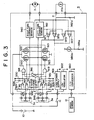
- FIG 3 is a circuit diagram of the control unit 9 of a second embodiment of this invention.
- This embodiment differs from the embodiment of Figure 2 in that a first temperature sensor 14a and a second temperature sensor 980a both comprise thermistors which increase in resistance with increasing temperature.
- the first temperature sensor 14a is connected between the output terminal of the voltage regulator 902 and a grounded resistor 982a, and the second temperature sensor 980a is connected between the output terminal of the voltage regulator 902 and another grounded resistor 981a.
- the junction of the first temperature sensor 14a and resistor 982a is connected to the positive input terminals of the fifth and sixth comparators 970 and 971, and the junction of the second temperature sensor 980a and resistor 981a is connected to the positive input terminals of the seventh and eighth comparators 972 and 973.
- the structure of this embodiment is otherwise the same as that of the embodiment of Figure 2, and it operates in the same manner.
- FIG 4 is a circuit diagram of the control unit 9 of a third embodiment of the present invention.
- This embodiment has the same basic structure as the embodiment of Figure 2 with a first temperature sensor 14 and a second temperature sensor 980 in the form of thermistors which decrease in resistance with increasing temperature.
- the junction of resistor 982 and the first temperature sensor 14 is connected to the positive input terminal of the fifth and sixth comparators 970 and 971 through a diode 988a.
- Two resistors 985 and 986 are connected in series between the output terminal of the voltage regulator 902 and ground. The junction of the two resistors is connected to the positive input terminals of the fifth and sixth comparators 970 and 971 by another diode 988b.
- resistor 981 and the second temperature sensor 980 is connected to the positive input terminal of the seventh and eighth comparators 972 and 973 through a diode 987a.
- Two resistors 983 and 984 are connected in series between the output terminal of the voltage regulator 902 and ground. The junction of the two resistors is connected to the positive input terminals of the seventh and eighth comparators 972 and 973 by another diode 987b.
- the structure of this embodiment is otherwise the same as that of the embodiment of Figure 2, and it operates in a similar manner.
- the diodes provide the effect that the motor current limit is independent of temperature until the temperature sensed by the temperature sensors exceeds a prescribed value.
- the maximum motor current is maintained at a constant value up to a threshold temperature of 80°C, for example, upon which the current limit begins to fall.
- the threshold temperature can be adjusted by changing the values of the series resistors 983 - 986.
Landscapes
- Engineering & Computer Science (AREA)
- Chemical & Material Sciences (AREA)
- Combustion & Propulsion (AREA)
- Transportation (AREA)
- Mechanical Engineering (AREA)
- Power Steering Mechanism (AREA)
- Steering Control In Accordance With Driving Conditions (AREA)
Applications Claiming Priority (2)
| Application Number | Priority Date | Filing Date | Title |
|---|---|---|---|
| JP63243214A JPH0292781A (ja) | 1988-09-28 | 1988-09-28 | モータ駆動式パワー・ステアリング装置 |
| JP243214/88 | 1988-09-28 |
Publications (2)
| Publication Number | Publication Date |
|---|---|
| EP0361725A1 true EP0361725A1 (fr) | 1990-04-04 |
| EP0361725B1 EP0361725B1 (fr) | 1993-12-01 |
Family
ID=17100524
Family Applications (1)
| Application Number | Title | Priority Date | Filing Date |
|---|---|---|---|
| EP89309210A Expired - Lifetime EP0361725B1 (fr) | 1988-09-28 | 1989-09-11 | Direction assistée par moteur |
Country Status (5)
| Country | Link |
|---|---|
| US (1) | US4986379A (fr) |
| EP (1) | EP0361725B1 (fr) |
| JP (1) | JPH0292781A (fr) |
| KR (1) | KR920005376B1 (fr) |
| DE (1) | DE68911098T2 (fr) |
Cited By (11)
| Publication number | Priority date | Publication date | Assignee | Title |
|---|---|---|---|---|
| WO1993005977A1 (fr) * | 1991-09-25 | 1993-04-01 | Frazer-Nash Technology Limited | Voiture electrique |
| FR2790242A1 (fr) * | 1999-02-27 | 2000-09-01 | Bosch Gmbh Robert | Procede et dispositif pour reduire la puissance maximale dans un etage final de direction assistee electrique |
| EP1035001A2 (fr) | 1999-03-08 | 2000-09-13 | Trw Inc. | Méthode et dispositif pour détecter une condition de calage d'un moteur d'un système de direction électrique |
| EP1162126A1 (fr) * | 2000-06-02 | 2001-12-12 | Koyo Seiko Co., Ltd. | Système d'assistance électrique de direction |
| FR2829088A1 (fr) * | 2001-08-30 | 2003-03-07 | Mitsubishi Electric Corp | Dispositif de commande de braquage |
| EP1388482A1 (fr) * | 2002-08-10 | 2004-02-11 | ZF Lenksysteme GmbH | Methode de réglage pour une pompe électro-hydraulique |
| FR2866301A1 (fr) * | 2004-02-12 | 2005-08-19 | Denso Corp | Systeme de direction assistee electrique pour un vehicule |
| EP1477386A3 (fr) * | 2003-05-12 | 2006-04-19 | Denso Corporation | Entraînement d'un moteur électrique et système de direction assistée motorisée |
| EP1810909A1 (fr) * | 2006-01-20 | 2007-07-25 | Jtekt Corporation | Dispositif de direction assistée électrique |
| EP1662647A3 (fr) * | 2004-11-30 | 2008-03-26 | NSK Ltd., | Dispositif de commande de direction assistée et méthode de commande de direction assistée |
| EP3702245A1 (fr) * | 2019-02-27 | 2020-09-02 | Jtekt Corporation | Système de direction |
Families Citing this family (22)
| Publication number | Priority date | Publication date | Assignee | Title |
|---|---|---|---|---|
| US5103926A (en) * | 1989-10-16 | 1992-04-14 | Toyoda Koki Kabushiki Kaisha | Power steering apparatus with electric motor |
| FR2685986B1 (fr) * | 1992-01-03 | 1994-06-24 | Valeo Electronique | Procede et dispositif de controle thermique d'un moteur electrique embarque a bord d'un vehicule et application a un systeme de direction assistee. |
| JP3945870B2 (ja) * | 1997-09-17 | 2007-07-18 | 株式会社ジェイテクト | 電動パワーステアリング装置 |
| KR100351410B1 (ko) * | 1997-12-26 | 2002-10-19 | 주식회사 만도 | 차량용 조향시스템 |
| JP3991416B2 (ja) * | 1998-01-23 | 2007-10-17 | 日本精工株式会社 | 電動パワーステアリング装置の制御装置 |
| JP3484968B2 (ja) * | 1998-02-24 | 2004-01-06 | 日本精工株式会社 | 電動パワーステアリング装置の制御装置 |
| JP3648392B2 (ja) * | 1998-09-18 | 2005-05-18 | 光洋精工株式会社 | パワーステアリング装置 |
| JP3652142B2 (ja) * | 1998-11-10 | 2005-05-25 | 光洋精工株式会社 | パワーステアリング装置 |
| KR100468491B1 (ko) * | 2000-09-15 | 2005-01-27 | 주식회사 만도 | 전동 파워 스티어링 시스템에서 모터의 과열 방지 방법 |
| JP4019408B2 (ja) * | 2001-07-10 | 2007-12-12 | オムロン株式会社 | コントロールユニット |
| US8337166B2 (en) * | 2001-11-26 | 2012-12-25 | Shurflo, Llc | Pump and pump control circuit apparatus and method |
| KR20040043800A (ko) * | 2002-11-20 | 2004-05-27 | 우석수 | 김 제조기의 발장전환장치 |
| KR20040043799A (ko) * | 2002-11-20 | 2004-05-27 | 우석수 | 김제조기의 발장이송장치 |
| JP3931181B2 (ja) * | 2004-06-02 | 2007-06-13 | 三菱電機株式会社 | 電動パワーステアリング装置 |
| DE102008028055A1 (de) * | 2008-06-12 | 2009-12-17 | Volkswagen Ag | Verfahren zur Bereitstellung der Lenkleistung für eine elektromechanische Lenkung |
| CN102165684B (zh) * | 2008-09-29 | 2014-02-12 | 丰田自动车株式会社 | 车辆的电源装置 |
| US9065375B2 (en) * | 2011-03-17 | 2015-06-23 | Toyota Jidosha Kabushiki Kaisha | Electric power steering device |
| JP6079596B2 (ja) * | 2013-12-06 | 2017-02-15 | トヨタ自動車株式会社 | 駐車支援装置 |
| JP2017193197A (ja) * | 2016-04-18 | 2017-10-26 | 株式会社ジェイテクト | 操舵制御装置 |
| WO2017207066A1 (fr) * | 2016-06-03 | 2017-12-07 | Thyssenkrupp Presta Ag | Estimation de température de bobine |
| CN106515842B (zh) * | 2016-10-12 | 2019-03-01 | 北京汽车股份有限公司 | 汽车的电动助力转向系统及其热保护控制方法和汽车 |
| DE102017125312A1 (de) * | 2017-10-27 | 2019-05-02 | Ebm-Papst Mulfingen Gmbh & Co. Kg | Anordnung zur Überwachung der Wicklungsgrenztemperatur |
Citations (3)
| Publication number | Priority date | Publication date | Assignee | Title |
|---|---|---|---|---|
| GB2145678A (en) * | 1983-08-08 | 1985-04-03 | Aisin Seiki | Power steering apparatus |
| EP0249506A2 (fr) * | 1986-06-12 | 1987-12-16 | Mitsubishi Denki Kabushiki Kaisha | Dispositif de direction assistée par moteur pour véhicule |
| FR2604408A1 (fr) * | 1986-09-29 | 1988-04-01 | Hitachi Ltd | Systeme de direction assistee entraine par un moteur |
Family Cites Families (6)
| Publication number | Priority date | Publication date | Assignee | Title |
|---|---|---|---|---|
| JPS62191267A (ja) * | 1986-02-17 | 1987-08-21 | Aisin Seiki Co Ltd | 電動式パワ−ステアリング装置 |
| JPS62251273A (ja) * | 1986-04-22 | 1987-11-02 | Honda Motor Co Ltd | 電動式パワ−ステアリング装置 |
| JPH069968B2 (ja) * | 1986-06-12 | 1994-02-09 | 三菱電機株式会社 | モ−タ駆動式パワ−ステアリング制御装置 |
| JPS6320271A (ja) * | 1986-07-14 | 1988-01-27 | Mitsubishi Electric Corp | モ−タ駆動式パワ−ステアリング制御装置 |
| JPS6371481A (ja) * | 1986-09-12 | 1988-03-31 | Mitsubishi Motors Corp | 車両の動力伝達装置 |
| JPH0686221B2 (ja) * | 1986-09-16 | 1994-11-02 | 本田技研工業株式会社 | 電動機式動力舵取装置 |
-
1988
- 1988-09-28 JP JP63243214A patent/JPH0292781A/ja active Pending
-
1989
- 1989-09-11 DE DE68911098T patent/DE68911098T2/de not_active Expired - Lifetime
- 1989-09-11 EP EP89309210A patent/EP0361725B1/fr not_active Expired - Lifetime
- 1989-09-18 US US07/408,335 patent/US4986379A/en not_active Expired - Lifetime
- 1989-09-19 KR KR1019890013428A patent/KR920005376B1/ko not_active Expired
Patent Citations (3)
| Publication number | Priority date | Publication date | Assignee | Title |
|---|---|---|---|---|
| GB2145678A (en) * | 1983-08-08 | 1985-04-03 | Aisin Seiki | Power steering apparatus |
| EP0249506A2 (fr) * | 1986-06-12 | 1987-12-16 | Mitsubishi Denki Kabushiki Kaisha | Dispositif de direction assistée par moteur pour véhicule |
| FR2604408A1 (fr) * | 1986-09-29 | 1988-04-01 | Hitachi Ltd | Systeme de direction assistee entraine par un moteur |
Non-Patent Citations (2)
| Title |
|---|
| PATENT ABSTRACTS OF JAPAN, vol. 12, no. 126 (M-687)[2973], 19th April 1988, page 61 M 687; & JP-A-62 251 273 (HONDA MOTOR CO. LTD) 02-11-1987 * |
| PATENT ABSTRACTS OF JAPAN, vol. 12, no. 294 (M-730)[3141], 11th August 1988, page 78 M 730; & JP-A-63 71 480 (HONDA MOTOR CO. LTD) 31-03-1988 * |
Cited By (17)
| Publication number | Priority date | Publication date | Assignee | Title |
|---|---|---|---|---|
| WO1993005977A1 (fr) * | 1991-09-25 | 1993-04-01 | Frazer-Nash Technology Limited | Voiture electrique |
| FR2790242A1 (fr) * | 1999-02-27 | 2000-09-01 | Bosch Gmbh Robert | Procede et dispositif pour reduire la puissance maximale dans un etage final de direction assistee electrique |
| EP1035001A3 (fr) * | 1999-03-08 | 2005-10-26 | TRW Automotive U.S. LLC | Méthode et dispositif pour détecter une condition de calage d'un moteur d'un système de direction électrique |
| EP1035001A2 (fr) | 1999-03-08 | 2000-09-13 | Trw Inc. | Méthode et dispositif pour détecter une condition de calage d'un moteur d'un système de direction électrique |
| EP1162126A1 (fr) * | 2000-06-02 | 2001-12-12 | Koyo Seiko Co., Ltd. | Système d'assistance électrique de direction |
| US6690138B2 (en) | 2000-06-02 | 2004-02-10 | Koyo Seiko Co., Ltd. | Electric power steering system |
| FR2829088A1 (fr) * | 2001-08-30 | 2003-03-07 | Mitsubishi Electric Corp | Dispositif de commande de braquage |
| EP1388482A1 (fr) * | 2002-08-10 | 2004-02-11 | ZF Lenksysteme GmbH | Methode de réglage pour une pompe électro-hydraulique |
| EP1477386A3 (fr) * | 2003-05-12 | 2006-04-19 | Denso Corporation | Entraînement d'un moteur électrique et système de direction assistée motorisée |
| US7164248B2 (en) | 2003-05-12 | 2007-01-16 | Denso Corporation | Electric motor drive apparatus and motor-driven power steering system |
| FR2866301A1 (fr) * | 2004-02-12 | 2005-08-19 | Denso Corp | Systeme de direction assistee electrique pour un vehicule |
| US7792619B2 (en) | 2004-02-12 | 2010-09-07 | Denso Corporation | Electrically driven power steering system for vehicle |
| EP1662647A3 (fr) * | 2004-11-30 | 2008-03-26 | NSK Ltd., | Dispositif de commande de direction assistée et méthode de commande de direction assistée |
| EP1810909A1 (fr) * | 2006-01-20 | 2007-07-25 | Jtekt Corporation | Dispositif de direction assistée électrique |
| US7537082B2 (en) | 2006-01-20 | 2009-05-26 | Jtekt Corporation | Electric power steering system |
| EP3702245A1 (fr) * | 2019-02-27 | 2020-09-02 | Jtekt Corporation | Système de direction |
| US11400970B2 (en) | 2019-02-27 | 2022-08-02 | Jtekt Corporation | Steering system |
Also Published As
| Publication number | Publication date |
|---|---|
| US4986379A (en) | 1991-01-22 |
| KR920005376B1 (ko) | 1992-07-02 |
| DE68911098D1 (de) | 1994-01-13 |
| EP0361725B1 (fr) | 1993-12-01 |
| KR900004576A (ko) | 1990-04-12 |
| DE68911098T2 (de) | 1994-06-23 |
| JPH0292781A (ja) | 1990-04-03 |
Similar Documents
| Publication | Publication Date | Title |
|---|---|---|
| US4986379A (en) | Motorized power steering apparatus | |
| US5000278A (en) | Motorized power steering apparatus | |
| JP3991416B2 (ja) | 電動パワーステアリング装置の制御装置 | |
| JP3518944B2 (ja) | モータ駆動装置 | |
| EP0249506B1 (fr) | Dispositif de direction assistée par moteur pour véhicule | |
| US5414627A (en) | Electric power steering control device for automotive vehicle | |
| EP0325148A2 (fr) | Direction assistée à moteur | |
| EP0686542B1 (fr) | Commande pour direction assistée électrique | |
| EP0395310B1 (fr) | Direction assistée par un moteur | |
| JPS60163766A (ja) | 電気式パワーステアリング装置及び方法 | |
| KR940004684B1 (ko) | 모터 구동식 파워 스티어링 장치 | |
| CN103442967A (zh) | 电动动力转向装置 | |
| US4986380A (en) | Motorized power steering apparatus | |
| JPH11286278A (ja) | 電動パワーステアリング装置の制御装置 | |
| EP0141626B1 (fr) | Appareil de contrôle pour direction assistée | |
| EP0360470B1 (fr) | Direction assistée par moteur | |
| JP3550978B2 (ja) | 電動パワーステアリング装置の制御装置 | |
| US6397971B1 (en) | Electrically powered steering system | |
| US4991676A (en) | Motorized power steering apparatus | |
| JP2002249062A (ja) | 電動パワーステアリング制御装置 | |
| JPH0520976U (ja) | 電動パワーステアリング装置 | |
| JP3641921B2 (ja) | 電動パワーステアリング装置の制御装置 | |
| JP3951753B2 (ja) | 電動パワーステアリング装置 | |
| JP2001026279A5 (fr) | ||
| JPH058722Y2 (fr) |
Legal Events
| Date | Code | Title | Description |
|---|---|---|---|
| PUAI | Public reference made under article 153(3) epc to a published international application that has entered the european phase |
Free format text: ORIGINAL CODE: 0009012 |
|
| AK | Designated contracting states |
Kind code of ref document: A1 Designated state(s): DE FR GB |
|
| 17P | Request for examination filed |
Effective date: 19900817 |
|
| 17Q | First examination report despatched |
Effective date: 19910625 |
|
| GRAA | (expected) grant |
Free format text: ORIGINAL CODE: 0009210 |
|
| AK | Designated contracting states |
Kind code of ref document: B1 Designated state(s): DE FR GB |
|
| REF | Corresponds to: |
Ref document number: 68911098 Country of ref document: DE Date of ref document: 19940113 |
|
| ET | Fr: translation filed | ||
| REG | Reference to a national code |
Ref country code: GB Ref legal event code: 727 |
|
| REG | Reference to a national code |
Ref country code: GB Ref legal event code: 727A |
|
| REG | Reference to a national code |
Ref country code: GB Ref legal event code: 727B |
|
| REG | Reference to a national code |
Ref country code: GB Ref legal event code: SP |
|
| PLBE | No opposition filed within time limit |
Free format text: ORIGINAL CODE: 0009261 |
|
| STAA | Information on the status of an ep patent application or granted ep patent |
Free format text: STATUS: NO OPPOSITION FILED WITHIN TIME LIMIT |
|
| 26N | No opposition filed | ||
| REG | Reference to a national code |
Ref country code: GB Ref legal event code: IF02 |
|
| PGFP | Annual fee paid to national office [announced via postgrant information from national office to epo] |
Ref country code: FR Payment date: 20080915 Year of fee payment: 20 |
|
| PGFP | Annual fee paid to national office [announced via postgrant information from national office to epo] |
Ref country code: GB Payment date: 20080917 Year of fee payment: 20 |
|
| PGFP | Annual fee paid to national office [announced via postgrant information from national office to epo] |
Ref country code: DE Payment date: 20080926 Year of fee payment: 20 |
|
| REG | Reference to a national code |
Ref country code: GB Ref legal event code: PE20 Expiry date: 20090910 |
|
| PG25 | Lapsed in a contracting state [announced via postgrant information from national office to epo] |
Ref country code: GB Free format text: LAPSE BECAUSE OF EXPIRATION OF PROTECTION Effective date: 20090910 |