EP0361889A2 - Mikroskop - Google Patents
Mikroskop Download PDFInfo
- Publication number
- EP0361889A2 EP0361889A2 EP89309830A EP89309830A EP0361889A2 EP 0361889 A2 EP0361889 A2 EP 0361889A2 EP 89309830 A EP89309830 A EP 89309830A EP 89309830 A EP89309830 A EP 89309830A EP 0361889 A2 EP0361889 A2 EP 0361889A2
- Authority
- EP
- European Patent Office
- Prior art keywords
- microscope
- viewed
- arm
- viewing stage
- folded
- Prior art date
- Legal status (The legal status is an assumption and is not a legal conclusion. Google has not performed a legal analysis and makes no representation as to the accuracy of the status listed.)
- Withdrawn
Links
Images
Classifications
-
- G—PHYSICS
- G02—OPTICS
- G02B—OPTICAL ELEMENTS, SYSTEMS OR APPARATUS
- G02B21/00—Microscopes
- G02B21/0004—Microscopes specially adapted for specific applications
- G02B21/0008—Microscopes having a simple construction, e.g. portable microscopes
Definitions
- This invention relates to microscopes, and particularly to a compact microscope which is easily portable and therefore particularly suitable for use in the field.
- a microscope having a substantially flat body incorporating a plurality of reflectors arranged so that a substantial proportion of the light path is folded, characterised in that the light path is folded in a single plane which is parallel to a flat outer surface of the body of the instrument which is arranged to form a viewing stage.
- the body is disc-shaped.
- This arrangement enables the microscope to be made compact, without unduly restricting the size of the viewing stage.
- a microscope having a movable illumination source, whose position can be changed from a first positioned, relative to the viewing stage, in which it provides illumination by transmitted light, and a second position in which it provides illumination by reflected light.
- the illumination source is mounted on an arm which is pivotally connected to the body of the microscope for movement between the first and second positions, the arm projecting outwardly from the body in the first position, so that the specimen to be viewed can be interposed between the illumination source and the body, in use, for viewing by transmitted light and the arm being folded into the body in the second position, so as to transmit light along an internal path which directs it onto the specimen for viewing by reflected light.
- the instrument is thus more versatile than known instruments since it can operate in two different modes.
- a microscope having a flat viewing stage of magnetic material, so that a magnetic slide carrier can be securely held on its surface.
- the carrier is preferably formed from a plastics material loaded with magnetic particles, and may be shaped so as to engage around the slide to hold it in position on the viewing stage.
- a compact microscope having an eyepiece comprising a circular eye lens in a housing projecting from the main body of the microscope, and a square field lens which is housed within the main body, so as to increase the effective field of view of the instrument.
- Such an arrangement increases the field of view of the microscope and is thus advantageous.
- the microscope comprises a generally flat disc-like body, one of the flat surfaces of which forms the viewing stage, and the illumination source comprises a lamp which is mounted on an arc-shaped arm, one end of which is pivotable about a radius of the body, so that the arm can be moved between a first position in which it projects upwardly from the surface, and a second position in which it fits into a correspondingly arc-shaped recess at the periphery of the surface.
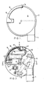
- the microscope body comprises a generally flat disc-shaped casing 2 and an eyepiece housing 4 which extends generally tangentially from the casing 2.
- One flat disc-shaped side 6 forms a viewing stage, and is preferably constructed of PTFE coated steel so that magnetic carriers can be mounted easily upon it.
- the light path from the eyepiece 4 is folded within the body of the instrument, as explained in more detail below, and terminates at an exit aperture 8 at the centre of the stage 6.
- An arc-shaped arm 10 fits into a corresponding recess 12 in the periphery of the body and is pivotable about an axis 14 which is radial to the disc-shaped body, so that the arm can be pivoted between the position shown in Figure 1, in which is is coplanar with the body, and the position shown in Figure 6, in which it is at right angles to the plane of the body, as explained in more detail below.
- the internal constuction of the microscope is illustrated in more detail in Figure 2.
- the light path from the eyepiece 4, which preferably has a magnification of approximately x10, is folded by means of two prisms 16 and 18, into a "z" shape to reach an objective lens 20 close to the centre of the instrument.
- the objective lens 20 may for example have a magnification of approximately x8 and is mounted on a pivotable arm 22 for focusing purposes.
- a supplementary negative lens 28 is mounted on a carousel pivotable about an axis 30, so that it can be swung into or out of the light path between the prisms 16 and 18.
- an external wheel control 32 is also provided on the underside of the casing (see Figure 2a).
- a prism 34 ( Figure 5) is mounted beneath the exit aperture 8 of the microscope, completing the light path between the eyepiece 4 and an object or specimen to be viewed on the stage 6.
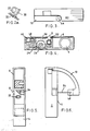
- a battery compartment 36 provides power for the illumination system which is housed in the arm 10.
- the wiring from the batteries is connected via switch 40 into the inner end 42 of the arm 10 which is formed with a tubular pivot fitted into a corresponding aperture in the casing 2.
- the wiring is passed down the arm 10 to a lamp holder 46 at the other end.
- the arm is formed as a 90° arc so that the axis of the lamp holder 46 is at right angles to the pivot 44.
- a prefocused bulb 48 (Figure 6) is mounted in the lamp holder 46 and, when the arm is in the inwardly folded position as illustrated in Figures 1 to 4, the light from the bulb 48 is directed radially inwardly along a path 50 ( Figure 4) to the centre of the body, where it is reflected upwardly to the exit aperture 8 by means of a mirror 52 mounted adjacent the central prism 34. This provides a reflected illumination mode.
- the surface of the stage 6 is completely free of obstructing projections so that the microscope can be used in its alternative, reflected illumination mode to examine any flat surface without formations of the instrument casing itself obstructing contact with the specimen.
- the entire body of the microscope can be placed against a fixed surface to enable it to be examined.
- the arm 10 When a slide mounted specimen is to be examined, the arm 10 is pivoted upwardly so that it extends at 90° to the surface 6, as shown in Figure 6, so that the light from the lamp 48 is directed towards the exit aperture 8 from outside the body and in this way the slide mounted on the stage 6 is illuminated by transmitted light. It will be appreciated that, because of the large flat uncluttered area presented by the stage 6, it is easy to manipulate the slide to any desired position.
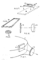
- Figure 7 shows a slide holder which is particularly adapted for use with a preferred construction of the microscope body in which the viewing stage 6 (c f Figure 1) is made of a magnetic material such as steel.
- the holder 60 comprises a rectangular plate having downwardly depending flanges 62 which engage around the edges of a slide 64 (shown in broken lines) and is made of a plastics material loaded with magnetic particles so as to securely engage with the stage 6.
- An aperture 65 allows light to pass through the slide.
- FIG. 8 An alternative form of holder 66 shown in Figure 8 is again moulded from a magnetic plastics material and is in the form of a "picture frame" which fits around the edges of the side, and another possible configuration 68, Figure 9, comprises a ring-shaped magnetic member which sits on top of the slide, with light passing through the centre.
- This device has the advantage that it can be used with slides of various sizes.
- Figure 10 shows a preferred form of wide-field eyepiece construction in which the eyelens 70 is circular, whilst the field lens 72 is square, providing a wider field of view than can normally be achieved. This is possible because the body of the microscope is not a cylindrical barrel as with a conventional instrument, and thus, as shown in Figure 11, the eyelens 70 can project out of the casing 2 whilst the field lens 72 is enclosed within the casing.
Landscapes
- Physics & Mathematics (AREA)
- Chemical & Material Sciences (AREA)
- Analytical Chemistry (AREA)
- General Physics & Mathematics (AREA)
- Optics & Photonics (AREA)
- Microscoopes, Condenser (AREA)
Applications Claiming Priority (2)
| Application Number | Priority Date | Filing Date | Title |
|---|---|---|---|
| GB888822668A GB8822668D0 (en) | 1988-09-27 | 1988-09-27 | Microscope |
| GB8822668 | 1988-09-27 |
Publications (2)
| Publication Number | Publication Date |
|---|---|
| EP0361889A2 true EP0361889A2 (de) | 1990-04-04 |
| EP0361889A3 EP0361889A3 (de) | 1991-03-27 |
Family
ID=10644318
Family Applications (1)
| Application Number | Title | Priority Date | Filing Date |
|---|---|---|---|
| EP19890309830 Withdrawn EP0361889A3 (de) | 1988-09-27 | 1989-09-27 | Mikroskop |
Country Status (2)
| Country | Link |
|---|---|
| EP (1) | EP0361889A3 (de) |
| GB (1) | GB8822668D0 (de) |
Cited By (4)
| Publication number | Priority date | Publication date | Assignee | Title |
|---|---|---|---|---|
| WO2004049031A1 (en) * | 2002-11-28 | 2004-06-10 | Dickinson, Richard, John | Portable microscope |
| GB2470118A (en) * | 2009-05-07 | 2010-11-10 | Cambridge Optronics Ltd | Compact microscope |
| US8118698B2 (en) | 2006-04-12 | 2012-02-21 | Litens Automotive Gmbh | Tensioner for an endless drive |
| CN103777340A (zh) * | 2014-01-26 | 2014-05-07 | 新乡医学院 | 磁性高分子材料载玻片及盖玻片及其制作方法 |
Family Cites Families (3)
| Publication number | Priority date | Publication date | Assignee | Title |
|---|---|---|---|---|
| US3775004A (en) * | 1971-05-11 | 1973-11-27 | Parco Scient Co | View screen microscopes |
| GB2081488A (en) * | 1980-06-23 | 1982-02-17 | Microstatic Sound Systems Ltd | Record player stylus viewing apparatus |
| NZ203838A (en) * | 1983-04-08 | 1988-02-12 | Donald Rivers Ensor | Inverted microscope |
-
1988
- 1988-09-27 GB GB888822668A patent/GB8822668D0/en active Pending
-
1989
- 1989-09-27 EP EP19890309830 patent/EP0361889A3/de not_active Withdrawn
Cited By (5)
| Publication number | Priority date | Publication date | Assignee | Title |
|---|---|---|---|---|
| WO2004049031A1 (en) * | 2002-11-28 | 2004-06-10 | Dickinson, Richard, John | Portable microscope |
| US8118698B2 (en) | 2006-04-12 | 2012-02-21 | Litens Automotive Gmbh | Tensioner for an endless drive |
| GB2470118A (en) * | 2009-05-07 | 2010-11-10 | Cambridge Optronics Ltd | Compact microscope |
| CN103777340A (zh) * | 2014-01-26 | 2014-05-07 | 新乡医学院 | 磁性高分子材料载玻片及盖玻片及其制作方法 |
| CN103777340B (zh) * | 2014-01-26 | 2015-12-30 | 新乡医学院 | 一种磁性高分子材料载玻片及盖玻片的制作方法 |
Also Published As
| Publication number | Publication date |
|---|---|
| EP0361889A3 (de) | 1991-03-27 |
| GB8822668D0 (en) | 1988-11-02 |
Similar Documents
| Publication | Publication Date | Title |
|---|---|---|
| US6414805B1 (en) | Reflected-light type fluorescence microscope and filter cassette used therefor | |
| KR910006736B1 (ko) | 투광, 반사광, 또는 투광 반사광 현미경 | |
| JPS61174505A (ja) | 顕微鏡用の直接照明装置 | |
| US5515201A (en) | Microscope-telescope combination fitted with illuminating apparatus | |
| JPS61501479A (ja) | 制御パネル用表示灯装置 | |
| US5021933A (en) | Illuminated magnifying glass | |
| US3285126A (en) | Desk level overhead projector | |
| EP0361889A2 (de) | Mikroskop | |
| US4285568A (en) | Microscope stage | |
| US4156561A (en) | Desk level overhead projector | |
| US6313944B2 (en) | Microscope turret assembly and a microscope | |
| EP0547232B1 (de) | Vorrichtung für vergrösserte beobachtung | |
| US6011586A (en) | Low-profile image formation apparatus | |
| US4008946A (en) | Pointer projecting means for microscopes | |
| US7167303B2 (en) | Microscope | |
| US7035002B2 (en) | Reflector turret for an inverted microscope | |
| JPH05119261A (ja) | 顕微鏡 | |
| US4444475A (en) | Microscope with projector | |
| US7206128B2 (en) | Illumination unit of stereomicroscope | |
| US4621913A (en) | Microscope with projector | |
| US6177986B1 (en) | Method of testing a lens having variable field angles | |
| US3516733A (en) | Projection head for compact overhead projector | |
| US6437857B1 (en) | Variable field angle and test pattern spatial frequency system for testing a lens | |
| JPH0720650Y2 (ja) | 偏射照明式倒立顕微鏡 | |
| US4257180A (en) | Microfiche viewer |
Legal Events
| Date | Code | Title | Description |
|---|---|---|---|
| PUAI | Public reference made under article 153(3) epc to a published international application that has entered the european phase |
Free format text: ORIGINAL CODE: 0009012 |
|
| AK | Designated contracting states |
Kind code of ref document: A2 Designated state(s): AT BE CH DE ES FR GB GR IT LI LU NL SE |
|
| PUAL | Search report despatched |
Free format text: ORIGINAL CODE: 0009013 |
|
| AK | Designated contracting states |
Kind code of ref document: A3 Designated state(s): AT BE CH DE ES FR GB GR IT LI LU NL SE |
|
| 17P | Request for examination filed |
Effective date: 19910918 |
|
| STAA | Information on the status of an ep patent application or granted ep patent |
Free format text: STATUS: THE APPLICATION IS DEEMED TO BE WITHDRAWN |
|
| 18D | Application deemed to be withdrawn |
Effective date: 19930401 |