EP0361980B1 - Dispositif de commande du calage des soupapes - Google Patents
Dispositif de commande du calage des soupapes Download PDFInfo
- Publication number
- EP0361980B1 EP0361980B1 EP89310036A EP89310036A EP0361980B1 EP 0361980 B1 EP0361980 B1 EP 0361980B1 EP 89310036 A EP89310036 A EP 89310036A EP 89310036 A EP89310036 A EP 89310036A EP 0361980 B1 EP0361980 B1 EP 0361980B1
- Authority
- EP
- European Patent Office
- Prior art keywords
- ring gear
- camshaft
- cylindrical member
- phase angle
- valve timing
- Prior art date
- Legal status (The legal status is an assumption and is not a legal conclusion. Google has not performed a legal analysis and makes no representation as to the accuracy of the status listed.)
- Expired - Lifetime
Links
Images
Classifications
-
- F—MECHANICAL ENGINEERING; LIGHTING; HEATING; WEAPONS; BLASTING
- F01—MACHINES OR ENGINES IN GENERAL; ENGINE PLANTS IN GENERAL; STEAM ENGINES
- F01L—CYCLICALLY OPERATING VALVES FOR MACHINES OR ENGINES
- F01L1/00—Valve-gear or valve arrangements, e.g. lift-valve gear
- F01L1/34—Valve-gear or valve arrangements, e.g. lift-valve gear characterised by the provision of means for changing the timing of the valves without changing the duration of opening and without affecting the magnitude of the valve lift
- F01L1/344—Valve-gear or valve arrangements, e.g. lift-valve gear characterised by the provision of means for changing the timing of the valves without changing the duration of opening and without affecting the magnitude of the valve lift changing the angular relationship between crankshaft and camshaft, e.g. using helicoidal gear
- F01L1/34403—Valve-gear or valve arrangements, e.g. lift-valve gear characterised by the provision of means for changing the timing of the valves without changing the duration of opening and without affecting the magnitude of the valve lift changing the angular relationship between crankshaft and camshaft, e.g. using helicoidal gear using helically teethed sleeve or gear moving axially between crankshaft and camshaft
- F01L1/34406—Valve-gear or valve arrangements, e.g. lift-valve gear characterised by the provision of means for changing the timing of the valves without changing the duration of opening and without affecting the magnitude of the valve lift changing the angular relationship between crankshaft and camshaft, e.g. using helicoidal gear using helically teethed sleeve or gear moving axially between crankshaft and camshaft the helically teethed sleeve being located in the camshaft driving pulley
-
- F—MECHANICAL ENGINEERING; LIGHTING; HEATING; WEAPONS; BLASTING
- F02—COMBUSTION ENGINES; HOT-GAS OR COMBUSTION-PRODUCT ENGINE PLANTS
- F02F—CYLINDERS, PISTONS OR CASINGS, FOR COMBUSTION ENGINES; ARRANGEMENTS OF SEALINGS IN COMBUSTION ENGINES
- F02F7/00—Casings, e.g. crankcases
- F02F7/006—Camshaft or pushrod housings
Definitions
- the present invention relates to an intake- and/or exhaust-valve timing control system which is optimally adapted for use in internal combustion engines. Particularly, to a system which is variably capable of controlling the intake- and/or exhaust-valve timing depending upon the operating state of the engine, for instance the magnitude of engine load or engine speed.
- valve timing is usually determined such that optimal engine performance is obtained, however the predetermined valve timing is not suitable under all operating conditions. For example, when the engine is operating within a range of low revoiutions, higher torque will be obtained with an intake-valve timing earlier than the predetermined valve timing.
- Such a conventional intake- and/or exhaust-valve timing control system for internal combustion engines has been disclosed in US-A-4,231,330, on which the preamble of claim 1 is based.
- a cam sprocket having a driven connection with the engine crankshaft is rotatably supported through a ring gear mechanism at the front end of the cam shaft.
- the ring gear mechanism includes a ring gear having an inner toothed portion engaging another toothed portion formed on the front end of the camshaft and an outer toothed portion engaging an inner toothed portion formed on the inner peripheral wall of the cam sprocket. In this manner, the ring gear rotatably engages between the cam sprocket and the camshaft.
- the ring gear is normally biased in the axial direction of the camshaft by spring means, such as a coil spring. At least one of the two meshing pairs of gears is helical. The result is that axial sliding movement of the ring gear relative to the camshaft causes the camshaft to rotate about the cam sprocket and therefore the phase angle between the camshaft and the cam sprocket (and consequently, the phase angle between the camshaft and the crankshaft) is varied relatively.
- the ring gear moves as soon as one of the two opposing forces acting on it, namely the preloading pressure of the above spring means or the oil pressure applied from the oil pump through the flow control valve to the ring gear, exceeds the other.
- the conventional valve timing control system also includes an end disc locked on the front end of the camshaft by threading such that the end disc hermetically closes the front opening of the substantially cylindrical cam sprocket in an air-tight fashion.
- an end disc locked on the front end of the camshaft by threading such that the end disc hermetically closes the front opening of the substantially cylindrical cam sprocket in an air-tight fashion.
- an object of the present invention to provide an intake- and/or exhaust-valve timing control system for internal combustion engines, in which the phase angle between camshaft sprocket (or timing pulley) and camshaft, that is the preset intake and/or exhaust valve timing relative to the crank angle, is easily and precisely adjusted.
- the invention provides an intake- and/or exhaust-valve timing control system for an internal combustion engine comprising: an inner cylindrical member firmly connected to one end of a camshaft of the engine, the inner cylindrical member including an outer toothed portion at the outer peripheral surface thereof; an outer cylindrical member having a driven connection with a crankshaft of the engine, the outer cylindrical member including an inner toothed portion at the inner peripheral surface thereof, the outer cylindrical member being axially positioned between the inner cylindrical member and an end plate covering an open end thereof in a fluid-tight manner; and a ring gear member including inner and outer toothed portions at the inner and outer peripheral surfaces thereof, the inner and outer toothed portions of the ring gear member being respectively meshed with the outer toothed portion of the camshaft and the inner toothed portion of the outer cylindrical member, at least one of the two meshing pairs of toothed portions being helical to provide sliding movement of the ring gear member in the axial direction of the camshaft, for changing a relative phase angle between the two cylindrical members in such a
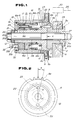
- Fig. 1 shows the front end section of a camshaft 1 provided for opening and closing an intake- and/or exhaust-valve (not shown).
- the camshaft 1 is journalled by a cylinder head 2 and a bearing member 3.
- An annular disc 4 is integrally formed at the front end 1a of the camshaft 1.
- the annular disc 4 has an annular, front flat surface 4a.
- Reference numeral 6 denotes an outer cylinder including a cam sprocket 9 driven by a timing chain 8 for transmitting torque from an engine crankshaft.
- the outer cylinder 6 includes a relatively long inner toothed portion 10 axially extending along the inner peripheral wall thereof.
- the outer cylinder 6 also includes a rear bore 11 having an inner diameter greater than the inner peripheral wall thereof.
- Reference numeral 12 denotes an inner cylinder integrally formed with a flange 14 having an annular, flat rear surface 14a, an annular, flat front surface 14b, and an outer peripheral surface 14c.
- the inner cylinder 12 includes an outer toothed portion formed on the outer peripheral surface thereof.
- the inner cylinder 12 is connected to the annular disc 4 to rotate with the camshaft 1 in such a manner that the rear surface 14a of the flange 14 abuts the front surface 4a of the disc 4. While the outer circumferential portion of the flange 14 is rotatably fitted into the rear bore 11 of the outer cylinder 6 such that the outer peripheral surface 14c abuts the inner peripheral surface of the outer cylinder 6 defining the rear bore 11, in an airtight fashion.
- a ring gear mechanism 15 is provided between the outer cylinder 6 and the inner cylinder 12.
- the ring gear mechanism 15 includes a ring gear member 16 which is comprised of a first ring gear element 16a and a second ring gear element 16b.
- the first and second ring gear elements 16a and 16b are formed in such a manner as to divide a relatively large ring gear including inner and outer toothed portions 16c and 16d into two parts by cutting or milling. Therefore, the first and second ring gear elements 16c and 16d have essentially the same geometry with regard to the inner and outer teeth.
- These ring gear elements 16c and 16d are interconnected by a plurality of connecting pins 18 which are fixed on the second ring gear element 16b through the annular hollow defined in the first ring gear element 16a.
- the annular hollow is traditionally filled with elastic material, such as a cylindrical rubber bushing attached by vulcanizing.
- elastic material such as a cylindrical rubber bushing attached by vulcanizing.
- a plurality of coil springs 17 may be provided in the annular hollow, while the springs 17 are supported by the heads of the connecting pins 18 serving as spring seats.
- the angular phase relationship between the ring gear elements 16a and 16b is designed so as to be set an angular position slightly offsets from an angular position in which the tooth traces between the two ring gear elements 16a and 16b are exactly aligned with each other.
- the inner and outer toothed portions 16c and 16d are respectively meshed with the inner toothed portion 10 of the outer cylinder 6 and the outer toothed portion 13 of the inner cylinder 12.
- At least one of the two meshing pairs of teeth (10,16d; 13,16c) is helical to provide axial sliding movement of the ring gear relative to the camshaft 1.
- An annular end plate 7 is fitted through a seal ring 32 into the front end of the outer cylinder 6 in an airtight fashion.
- the end plate 7 and the inner cylinder 12 are fixed together on the disc 4 of the camshaft 1, through a relatively thick plain washer 21 having a high rigidity, by a bolt 20 such that the bolt 20 is screwed through the cylindrical hollow defined in the inner cylinder 12 into a threaded portion 5a formed at the outermost end of the inner bore 5 defined in the front end 1a of the camshaft 1.
- the annular end plate 7 When the bolt 20 is screwed into the front end 1a of the camshaft 1, the annular end plate 7 is firmly fixed on the inner cylinder 12 in such a manner that the inner peripheral surface of the end plate 7 is press-fitted into the outer peripheral surface of the front end of the inner cylinder 12.
- the bolt is comprised of a head 20a, an intermediate shaft section 20b, and a threaded section 20c engaging with the threaded portion 5a of the camshaft 1.
- a pressure chamber 19 is defined by the inner wall of the end plate 7, the front end of the first ring gear element 16a, and the front end of the inner cylinder 12 for introducing working fluid fed from the oil pan (not shown) via the engine oil pump (not shown).
- the axially forward movement of the ring gear member 16 is restricted by the abutment between an adjusting screw 33 (which is further described below) and the front end of the first ring gear element 16a.
- the axially backward movement of the ring gear member 16 is restricted by the abutment between the front surface 14b of the flange 14 and the the rear end of the second ring gear element 16b.
- the inner cylinder 12 and camshaft 1 are interconnected through a knock-pin 22 serving as a positioning pin.
- the knock-pin 22 is press-fitted into a hole 4b bored through the front surface 4a of the disc 4 in the axial direction of the camshaft 1.
- the hole 4a is bored in a position corresponding to a particular phase angle of the camshaft 1.
- a positioning hole 23 for the knock-pin 22 is axially bored through the rear surface 14a into the flange 14 of the inner cylinder 12. As shown in Fig.
- the hole 23 is designed to be bored in the flange 14 such that the hole 23 is offset by a predetermined angle ⁇ from a datum line X, drawn from the center P of the sprocket 9 to the top of a predetermined tooth 9a (for instance, as marked by the timing mark) of the sprocket 9, under a condition wherein the inner and outer cylinders 6 and 12 and the ring gear mechanism 15 are assembled as a unit.
- the holes 4b and 23 are formed in a manner so as to essentially the same distance relative to the axis of the camshaft 1. In this manner, the phase angle between the camshaft 1 and the sprocket 9 can be set to be always constant.
- a ring gear drive mechanism for the previously described ring gear member 16 comprises a hydraulic circuit 24 for supplying and draining the working fluid from the oil pan to the pressure chamber 19, a compression spring 25 disposed between the second ring gear element 16b and the flange 14 for normally biasing the ring gear member 16 in an axially forward direction, and an electromagnetic flow control valve 30 for controlling the amount of the working fluid flowing through the hydraulic circuit 24.
- the hydraulic circuit 24 includes an oil supply passage 27 radially extending in the camshaft 1, an intermediate oil passage 28 defined between the outer periphery of the shaft section 20b of the bolt 20 and the inner peripheries of the inner cylinder 12 and the front end 1a of the camshaft 1, a communication passage 29 intercommunicating the pressure chamber 19 and the intermediate oil passage 28, and an exhaust passage 31 bored in the outer cylinder 6 in the vicinity of the sprocket 9 for intercommunicating a rear fluid chamber employing a return spring 25 and an internal space defined by the cylinder head 2 and the cylinder head cover (not shown).
- the oil supply passage 27 communicates upstream thereof through an annular oil passage 3a defined between the outer peripheral surface of the front journalled section of the camshaft 1 and the semi-circular curved surface of the cylinder head 2 and the bearing member 3, via the flow control valve 30, a main oil gallery 26, with the oil pump (not shown).
- the flow control valve 30 is controlled by a controller (not shown) which determines the operating state of the engine on the basis of signals output from various sensors, such as a crank angle sensor for monitoring the crank angle of the crankshaft, and an air flow meter for monitoring the amount of intake air introduced through the air cleaner.
- the intake- and/or exhaust-valve timing control system for internal combustion engines operates as follows.
- the control signal from the previously described controller is in an OFF state, with the result that the flow control valve 30 blocks the flow of working fluid fed through the oil supply passage 27 to the pressure chamber 19. Since the oil within the pressure chamber is exhausted through apertures defined between the two meshing pairs of teeth (10,16d; 13,16c) via the exhaust passage 31 to the internal space defined by the cylinder head 2 and the cylinder head cover, the pressure within the pressure chamber 19 becomes low, while the working fluid flowing through the above mentioned apertures serves to lubricate the ring gear mechanism 15. As a result, as shown in Fig. 1, the ring gear member 16 is positioned at the leftmost position (viewing Fig. 1) by the spring 25. Under this condition, the relative phase angle between the sprocket 9 and the camshaft 1 is set to a predetermined phase angle in which intake- and/or exhaust-valve timing relative to the crank angle is initialized.
- the control signal from the controller is in an ON state, with the result that the pressurized working fluid from the oil pump (not shown) is through the main oil oil gallery 26, the flow control valve 30, the oil supply passage 27, to the pressure chamber 19, in that order.
- the ring gear member 16 is moved in the right direction (viewing Fig. 1) against the spring force generated by the spring 25. Therefore, the phase angle between the outer cylinder 6 and the inner cylinder 12 (corresponding to the phase angle between the outer cylinder 6 and the camshaft 1) is relatively changed to a predetermined phase angle which corresponds to an optimal phase angle during high engine load conditions. In this manner, the intake- and/or exhaust-valve timing is variably controlled dependent upon the operating state of the engine.
- the phase angle between the sprocket 9 and the camshaft 1 is naturally set to a predetermined value to obtain an optimal intake- and/or exhaust-valve timing relative to the crank angle.
- the phase angle between the sprocket 9 and the camshaft 1 is determined by only the two positioning holes 4b and 23 and the knock-pin 22, the complicated structure for fine adjusting phase angle between the sprocket 9 and the camshaft 1 is avoided.
- the knock-pin 22 is press-fitted into the hole 4b bored in the annular disc 4 in the axial direction of the camshaft 1
- the knock-pin may also be press-fitted into a hole bored in the annular disc 4 in the radial direction of the camshaft 1 as a positioning device for determining the phase angle between the sprocket 9 and the camshaft 1.
- an adjusting screw 33 including a head 33a and a threaded shaft 33b is attached to the end plate 7 and the positioning hole 23 is previously bored in the flange 14 of the inner cylinder 12.
- the positioning hole 23 according to the first embodiment must be bored with an extremely high machining accuracy after the position of the hole 23 is precisely determined in a relative phase angle relationship between the knock-pin 22 and the predetermined tooth 9a of the sprocket 9 in accordance with the positioning method shown in Fig. 2, however assuming that the angular position of the hole 23 is slightly offset from a predetermined position, a device for fine adjusting or compensating the offset is included.
- the adjusting screw 33 is therefore provided for fine adjusting or compensating such an offset.
- the adjusting screw 33 adjusts the phase angle between the sprocket 9 and the camshaft 1 such that the the top end of the threaded shaft 33b of the adjusting screw 33 moves the ring gear member 16 in the axial direction in a manner so as to screw the head 33a around by means of a hexagon socket screw key.
- phase angle between the sprocket 9 and the camshaft 1 is adjusted in accordance with the following procedure.
- the inner and outer cylinders 6 and 12, and the ring gear mechanism 15 are assembled as a unit. Under this condition, if the phase angle between the top of the predetermined tooth 9a of the sprocket 9 and the hole 23 is different from the predetermined phase angle ⁇ , the adjusting screw 33 is for instance rotated clockwise and the top end of the threaded shaft 33b of the screw 33 pushes the front end of the first ring gear element 16a and therefore the ring gear member 16 is moved in the right direction (viewing Fig. 1).
- the outer cylinder 6 rotates in a predetermined direction depending upon the direction of the tooth traces of the helical gear, since at least one of the two meshed pairs of toothed portions (10,16d; 13,16c) is helical. While the screw 33 is rotated counterclockwise, the ring gear member 16 is returned to the left direction (viewing Fig. 1) by the spring 25 and as a result the outer cylinder 6 is rotated in a direction opposing the above mentioned predetermined direction.
- the outer cylinder 6 is rotated relative to the inner cylinder 12 and thus the phase angle between the sprocket 9 and the camshaft 1 is fine adjusted such that the hole 23 is precisely offset by the predetermined phase angle ⁇ from the datum line X as clearly seen in Fig. 2.
- the fine adjusted unit is firmly secured to the front end 1a of the camshaft 1 by the bolt 20, while the knock-pin 22 is press-fitted into the hole 23.
- the phase angle between the sprocket 9 and the camshaft 1 is easily and precisely set to a predetermined value at the same time when the unit is assembled on the front end of the camshaft 1.
- camshaft sprocket associated with a timing chain is used for the timing control system according to the invention
- camshaft sprocket may be replaced with a timing pulley associated with a timing belt.
Landscapes
- Engineering & Computer Science (AREA)
- Mechanical Engineering (AREA)
- General Engineering & Computer Science (AREA)
- Valve-Gear Or Valve Arrangements (AREA)
- Valve Device For Special Equipments (AREA)
Claims (2)
- Système de commande du réglage des soupapes d'admission et/ou d'échappement pour un moteur à combustion interne comprenant : un élément cylindrique interne (12) connecté ferment à une extrémité d'un arbre à cames (1) du moteur, l'élément cylindrique interne comprenant une portion dentée externe (13) à sa surface périphérique externe; un élément cylindrique externe (6) possédant une connexion menée (8) avec un vilebrequin du moteur, l'élément cylindrique externe comprenant une portion dentée interne (10) à sa surface périphérique interne, l'élément cylindrique externe étant positionné axialement entre l'élément cylindrique interne et une plaque d'extrémité (7) couvrant une extrémité ouverte de celui-ci d'une manière étanche au fluide; et un élément de couronne dentée (16) comprenant des portions dentées intérieure et extérieure (16c,16d) à ses surfaces périphériques intérieure et extérieure, les portions dentées intérieure et extérieure (16c,16d) de l'élément de couronne dentée (16) engrenant respectivement avec la portion dentée extérieure (13) de l'arbre à cames (1,14) et la portion dentée intérieure (10) de l'élément cylindrique externe (6), au moins l'une des deux paires engrenées des portions dentées étant hélicoïdale afin de réaliser un mouvement coulissant de l'élément de couronne dentée dans la direction axiale de l'arbre à cames afin de changer un angle de phase relatif entre les deux eléments cylindriques de manière à commander le réglage des soupapes d'admission et/ou d'échappement du moteur; caractérisé par des moyens (33) pour ajuster finement un réglage initial d'un angle de phase relatif entre les deux élements cylindriques après l'installation dudit élément de couronne dentée (16) entre les deux éléments cylindriques (6,12), lesdits moyens d'ajustage comprenant une vis d'ajustage venant en prise avec une extrémité dudit élément de couronne dentée afin de limiter une valeur maximale d'un mouvement coulissant axial dudit élément de couronne dentée (16).
- Système de commande du réglage des soupapes d'admission et/ou d'échappement selon la revendication 1, caractérisé par un axe (22) prévu sur ladite une extrémité (4) de l'arbre à cames, à une position angulaire prédéterminée de l'arbre à cames; et un trou de positionnement (23) pratiqué dans l'élément cylindrique interne, pour emmancher l'axe (22) dans celui-ci, la position du trou de positionnement étant déterminée suivant une relation d'angle de phase relative entre ledit axe et un point particulier (9a) sur l'élément cylindrique externe, ce point particulier définissant une position angulaire de référence de l'élément cylindrique externe.
Applications Claiming Priority (6)
| Application Number | Priority Date | Filing Date | Title |
|---|---|---|---|
| JP128918/88 | 1988-09-30 | ||
| JP1988128918U JP2517794Y2 (ja) | 1988-09-30 | 1988-09-30 | 内燃機関のバルブタイミング制御装置 |
| JP133668/88 | 1988-10-13 | ||
| JP13366888U JPH0254306U (fr) | 1988-10-13 | 1988-10-13 | |
| JP13366988U JPH0254307U (fr) | 1988-10-13 | 1988-10-13 | |
| JP133669/88 | 1988-10-13 |
Publications (2)
| Publication Number | Publication Date |
|---|---|
| EP0361980A1 EP0361980A1 (fr) | 1990-04-04 |
| EP0361980B1 true EP0361980B1 (fr) | 1994-03-30 |
Family
ID=27315838
Family Applications (1)
| Application Number | Title | Priority Date | Filing Date |
|---|---|---|---|
| EP89310036A Expired - Lifetime EP0361980B1 (fr) | 1988-09-30 | 1989-10-02 | Dispositif de commande du calage des soupapes |
Country Status (3)
| Country | Link |
|---|---|
| US (1) | US4996955A (fr) |
| EP (1) | EP0361980B1 (fr) |
| DE (1) | DE68914231T2 (fr) |
Families Citing this family (8)
| Publication number | Priority date | Publication date | Assignee | Title |
|---|---|---|---|---|
| DE4024057C1 (fr) * | 1990-07-28 | 1991-09-19 | Dr.Ing.H.C. F. Porsche Ag, 7000 Stuttgart, De | |
| DE4024056C1 (fr) * | 1990-07-28 | 1991-09-19 | Dr.Ing.H.C. F. Porsche Ag, 7000 Stuttgart, De | |
| US5205248A (en) * | 1990-11-16 | 1993-04-27 | Atsugi Unisia Corp. | Intake- and/or exhaust-valve timing control system for internal combustion engines |
| IT1259099B (it) * | 1992-05-19 | 1996-03-11 | Carraro Spa | Variatore di fase |
| US5588404A (en) * | 1994-12-12 | 1996-12-31 | General Motors Corporation | Variable cam phaser and method of assembly |
| US5542383A (en) * | 1995-05-04 | 1996-08-06 | Ford Motor Company | Dual output camshaft phase controller |
| WO2006047099A2 (fr) | 2004-10-26 | 2006-05-04 | George Louie | Dispositif de commande de distribution à réglage continu |
| CN108798816A (zh) * | 2018-07-03 | 2018-11-13 | 广西玉柴机器股份有限公司 | 顶置凸轮轴齿轮的正时定位机构 |
Citations (1)
| Publication number | Priority date | Publication date | Assignee | Title |
|---|---|---|---|---|
| FR2526858A1 (fr) * | 1982-05-17 | 1983-11-18 | Alfa Romeo Auto Spa | Dispositif permettant de varier automatiquement le calage d'un arbre a cames |
Family Cites Families (11)
| Publication number | Priority date | Publication date | Assignee | Title |
|---|---|---|---|---|
| US3734073A (en) * | 1971-06-01 | 1973-05-22 | R Walter | Adjustable camshaft sprocket wheel |
| IT1093715B (it) * | 1978-03-24 | 1985-07-26 | Alfa Romeo Spa | Variatore di fase della distribuzione per motore alternativo a combustione interna |
| JPS58119908A (ja) * | 1982-01-12 | 1983-07-16 | Toyota Motor Corp | 可変バルブタイミング装置 |
| JPS58162708A (ja) * | 1982-03-24 | 1983-09-27 | Toyota Motor Corp | 内燃機関のバルブタイミング制御装置 |
| JPS5987214A (ja) * | 1982-11-12 | 1984-05-19 | Toyota Motor Corp | 内燃機関のバルブタイミング制御装置 |
| JPS6017214A (ja) * | 1983-07-11 | 1985-01-29 | Toyota Motor Corp | 内燃機関の動弁装置 |
| US4601266A (en) * | 1983-12-30 | 1986-07-22 | Renold Plc | Phasing device for machine applications |
| US4811698A (en) * | 1985-05-22 | 1989-03-14 | Atsugi Motor Parts Company, Limited | Valve timing adjusting mechanism for internal combustion engine for adjusting timing of intake valve and/or exhaust valve corresponding to engine operating conditions |
| JP2543846B2 (ja) * | 1985-06-28 | 1996-10-16 | 株式会社ユニシアジェックス | 内燃機関のバルブタイミング調整装置の組立方法 |
| JPS61279713A (ja) * | 1985-06-06 | 1986-12-10 | Atsugi Motor Parts Co Ltd | 内燃機関のバルブタイミング調整装置 |
| US4841924A (en) * | 1988-08-18 | 1989-06-27 | Eaton Corporation | Sealed camshaft phase change device |
-
1989
- 1989-09-29 US US07/414,241 patent/US4996955A/en not_active Expired - Fee Related
- 1989-10-02 DE DE68914231T patent/DE68914231T2/de not_active Expired - Fee Related
- 1989-10-02 EP EP89310036A patent/EP0361980B1/fr not_active Expired - Lifetime
Patent Citations (1)
| Publication number | Priority date | Publication date | Assignee | Title |
|---|---|---|---|---|
| FR2526858A1 (fr) * | 1982-05-17 | 1983-11-18 | Alfa Romeo Auto Spa | Dispositif permettant de varier automatiquement le calage d'un arbre a cames |
Also Published As
| Publication number | Publication date |
|---|---|
| DE68914231T2 (de) | 1994-09-08 |
| DE68914231D1 (de) | 1994-05-05 |
| US4996955A (en) | 1991-03-05 |
| EP0361980A1 (fr) | 1990-04-04 |
Similar Documents
| Publication | Publication Date | Title |
|---|---|---|
| EP0147209B1 (fr) | Dispositif de variation de phase pour application des machines | |
| US5247914A (en) | Intake- and/or exhaust-valve timing control system for internal combustion engines | |
| EP1128028B1 (fr) | Dispositif de commande du calage des soupapes | |
| US5203290A (en) | Intake and/or exhaust-valve timing control sytem for internal combustion engine | |
| US5333577A (en) | Variable valve operation timing control device | |
| US4811698A (en) | Valve timing adjusting mechanism for internal combustion engine for adjusting timing of intake valve and/or exhaust valve corresponding to engine operating conditions | |
| US5566651A (en) | Device for continuous angular adjustment between two shafts in driving relationship | |
| US6244230B1 (en) | Variable valve timing apparatus | |
| US5809955A (en) | Hydraulic actuator and variable valve driving mechanism making use of the same | |
| EP0340821B1 (fr) | Dispositif automatique de variation du calage de la distribution pour un moteur à combustion interne | |
| US6170448B1 (en) | Variable valve timing apparatus | |
| EP1357258A2 (fr) | Electrovanne à force variable pour dispositif déphaseur d'arbre à cames | |
| US5309873A (en) | Valve timing control system for internal combustion engine | |
| EP0488156B1 (fr) | Dispositif de commande de calage des soupapes d'admission ou d'échappement pour moteurs à combustion | |
| EP0818610B1 (fr) | Dispositifs de commande du calage des soupapes | |
| US4996955A (en) | Intake- and/or exhaust-valve timing control system for internal combustion engines | |
| US4332227A (en) | Injection timing device for internal combustion engines | |
| US5803029A (en) | Valve performance controller for internal combustion engine | |
| EP0777037B2 (fr) | Moteur à combustion interne avec dispositif de commande du dèphasage | |
| GB2024989A (en) | Fuel injection timing devixe for internal combustionengines | |
| US5040499A (en) | Intake- and/or exhaust-valve timing control system for internal combustion engines | |
| EP0486068B1 (fr) | Dispositif de commande du calage des soupapes d'admission et/ou d'échappement pour moteurs à combustion interne | |
| US5113814A (en) | Valve timing control system for internal combustion engine with enhanced response characteristics in adjustment of valve timing | |
| EP0362076B1 (fr) | Dispositif de commande du calage des soupapes d'un moteur à combustion interne | |
| US5150671A (en) | Intake- and/or exhaust-valve timing control system for internal combustion engines |
Legal Events
| Date | Code | Title | Description |
|---|---|---|---|
| PUAI | Public reference made under article 153(3) epc to a published international application that has entered the european phase |
Free format text: ORIGINAL CODE: 0009012 |
|
| AK | Designated contracting states |
Kind code of ref document: A1 Designated state(s): DE FR GB |
|
| 17P | Request for examination filed |
Effective date: 19900917 |
|
| 17Q | First examination report despatched |
Effective date: 19911212 |
|
| RAP1 | Party data changed (applicant data changed or rights of an application transferred) |
Owner name: UNISIA JECS CORPORATION |
|
| GRAA | (expected) grant |
Free format text: ORIGINAL CODE: 0009210 |
|
| AK | Designated contracting states |
Kind code of ref document: B1 Designated state(s): DE FR GB |
|
| REF | Corresponds to: |
Ref document number: 68914231 Country of ref document: DE Date of ref document: 19940505 |
|
| ET | Fr: translation filed | ||
| PLBE | No opposition filed within time limit |
Free format text: ORIGINAL CODE: 0009261 |
|
| STAA | Information on the status of an ep patent application or granted ep patent |
Free format text: STATUS: NO OPPOSITION FILED WITHIN TIME LIMIT |
|
| 26N | No opposition filed | ||
| PGFP | Annual fee paid to national office [announced via postgrant information from national office to epo] |
Ref country code: DE Payment date: 20000925 Year of fee payment: 12 |
|
| PGFP | Annual fee paid to national office [announced via postgrant information from national office to epo] |
Ref country code: GB Payment date: 20000927 Year of fee payment: 12 |
|
| PGFP | Annual fee paid to national office [announced via postgrant information from national office to epo] |
Ref country code: FR Payment date: 20001010 Year of fee payment: 12 |
|
| PG25 | Lapsed in a contracting state [announced via postgrant information from national office to epo] |
Ref country code: GB Free format text: LAPSE BECAUSE OF NON-PAYMENT OF DUE FEES Effective date: 20011002 |
|
| REG | Reference to a national code |
Ref country code: GB Ref legal event code: IF02 |
|
| GBPC | Gb: european patent ceased through non-payment of renewal fee |
Effective date: 20011002 |
|
| PG25 | Lapsed in a contracting state [announced via postgrant information from national office to epo] |
Ref country code: FR Free format text: LAPSE BECAUSE OF NON-PAYMENT OF DUE FEES Effective date: 20020628 |
|
| PG25 | Lapsed in a contracting state [announced via postgrant information from national office to epo] |
Ref country code: DE Free format text: LAPSE BECAUSE OF NON-PAYMENT OF DUE FEES Effective date: 20020702 |
|
| REG | Reference to a national code |
Ref country code: FR Ref legal event code: ST |