EP0362038A1 - Regelvorrichtung für eine sperrbare Gasfeder - Google Patents
Regelvorrichtung für eine sperrbare Gasfeder Download PDFInfo
- Publication number
- EP0362038A1 EP0362038A1 EP89402612A EP89402612A EP0362038A1 EP 0362038 A1 EP0362038 A1 EP 0362038A1 EP 89402612 A EP89402612 A EP 89402612A EP 89402612 A EP89402612 A EP 89402612A EP 0362038 A1 EP0362038 A1 EP 0362038A1
- Authority
- EP
- European Patent Office
- Prior art keywords
- lever
- gas spring
- windows
- end piece
- section
- Prior art date
- Legal status (The legal status is an assumption and is not a legal conclusion. Google has not performed a legal analysis and makes no representation as to the accuracy of the status listed.)
- Granted
Links
- 230000000284 resting effect Effects 0.000 claims description 2
- 238000006073 displacement reaction Methods 0.000 abstract 1
- 238000002788 crimping Methods 0.000 description 2
- 208000031968 Cadaver Diseases 0.000 description 1
- 240000008042 Zea mays Species 0.000 description 1
- 230000000712 assembly Effects 0.000 description 1
- 238000000429 assembly Methods 0.000 description 1
- 230000000903 blocking effect Effects 0.000 description 1
- 230000006835 compression Effects 0.000 description 1
- 238000007906 compression Methods 0.000 description 1
- 230000000994 depressogenic effect Effects 0.000 description 1
- 238000003780 insertion Methods 0.000 description 1
- 230000037431 insertion Effects 0.000 description 1
- 238000000034 method Methods 0.000 description 1
- 238000000465 moulding Methods 0.000 description 1
- 230000007935 neutral effect Effects 0.000 description 1
- 230000000149 penetrating effect Effects 0.000 description 1
- 238000010079 rubber tapping Methods 0.000 description 1
Images

Classifications
-
- A—HUMAN NECESSITIES
- A47—FURNITURE; DOMESTIC ARTICLES OR APPLIANCES; COFFEE MILLS; SPICE MILLS; SUCTION CLEANERS IN GENERAL
- A47C—CHAIRS; SOFAS; BEDS
- A47C3/00—Chairs characterised by structural features; Chairs or stools with rotatable or vertically-adjustable seats
- A47C3/20—Chairs or stools with vertically-adjustable seats
- A47C3/30—Chairs or stools with vertically-adjustable seats with vertically-acting fluid cylinder
-
- F—MECHANICAL ENGINEERING; LIGHTING; HEATING; WEAPONS; BLASTING
- F16—ENGINEERING ELEMENTS AND UNITS; GENERAL MEASURES FOR PRODUCING AND MAINTAINING EFFECTIVE FUNCTIONING OF MACHINES OR INSTALLATIONS; THERMAL INSULATION IN GENERAL
- F16F—SPRINGS; SHOCK-ABSORBERS; MEANS FOR DAMPING VIBRATION
- F16F9/00—Springs, vibration-dampers, shock-absorbers, or similarly-constructed movement-dampers using a fluid or the equivalent as damping medium
- F16F9/02—Springs, vibration-dampers, shock-absorbers, or similarly-constructed movement-dampers using a fluid or the equivalent as damping medium using gas only or vacuum
- F16F9/0209—Telescopic
- F16F9/0245—Means for adjusting the length of, or for locking, the spring or dampers
- F16F9/0263—Means for adjusting the length of, or for locking, the spring or dampers characterised by actuation means, e.g. manually-operated lever arrangement
Definitions
- the present invention relates to a control device for a lockable gas spring.
- Gas springs of the lockable type are used on many devices (beds, armchairs, crutches, etc.) to ensure continuous adjustment, mass balancing, speed regulation; these three functions are done together or separately. They are fitted with a control finger located at one of their ends (rod side or tube side). This finger must be moved axially by a few millimeters, the return being done automatically; the movement is always in the direction of the gas spring piston.
- the gas spring is most often mounted between a fixed point and a pivoting movable point, which poses a problem in ensuring this control. Indeed, the gas spring during its maneuver pivots around its fixed point because the movable point describes an arc of a circle, it is therefore necessary to provide a control device adapted to this pivoting.
- DE-U-69 10925 has proposed a device in which the finger of a locking device is actuated by a lever whose articulation is simply constituted by a hole which passes through a tubular piece which surrounds the finger.
- additional documents are still necessary to prevent unwanted movement of the lever.
- the object of the present invention is to provide an actuating device in which the number of parts is as small as possible, and which however operates with great security.
- the invention provides a control device for a lockable gas spring, comprising a tubular end-piece designed to be fixed on a fixing end-piece which is provided at the end of the body or rod of a spring lockable gas, or which constitutes an extension of a wall of the lockable spring, this fixing end piece being traversed axially by a sliding control finger, a head of which projects at the end of the fixing end piece, and a lever actuation, which enters the tubular endpiece through a radial window, and which can move the head of the control finger axially when it pivots in a plane containing the axis of the gas spring by resting on an edge of said window , this device having the particularity that the actuating lever comprises an enlarged part intended to come into contact with the head of the actuating finger, this enlarged part being framed by two more parts small section, in that it is provided, in the tubular endpiece, two diametrically opposed windows elongated axially and, which, at least in their
- two windows are identical in shape.
- said elastic means are constituted by the internal pressure of the gas spring, which tends to push the control finger outwards.
- the means for preventing the enlarged portion of the lever from entering the enlarged portion of the window or windows are constituted by the end of the attachment fitting for the gas spring.
- the tubular endpiece carries a support piece which has a means of stopping the sheath of a sheathed cable control, while the lever comprises means for fixing the cable of said control, these means being spaced from the widened portion and the small section portions of said lever.
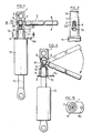
- Figures 1 and 2 show a combined tip 1 in longitudinal section mounted on a lockable gas spring.
- the combined end piece 1 is screwed onto the threaded end piece 7 of a lockable gas spring 11, the control of which is located on the bottom of the tube (opposite the rod).
- the control lever 2 is in the neutral position, it is held on the supports 4 and 5 by the control finger 6 of the lockable gas spring.
- a plate 9 provided with a hole 9a provided for the sheath stop 18 fixed to the base of the combined tip 1.
- the control finger 6 is slightly prestressed by the enlarged part 24 of the control lever d2, located between two thinner parts 25, 26 corresponding to the supports 4 and 5.
- the combined end piece 1 has a through hole 3 drilled radially for fixing the gas spring on an axis.
- the combined end piece 1 is screwed onto the rod 8 of a lockable gas spring 12, the control finger 6 of which is located at the end of this rod.
- the lever 2 is actuated, the control finger is depressed by the enlarged part 24.
- the lever bears on point 5 of the endpiece when it is pushed, and on point 4 when it is pulled.
- the plate 9 is fixed by crimping on the base of the combined end piece 1.
- the enlarged part 24 of the lever 2 has a double function: it biases the control finger 6 and, it holds the lever 2 captive in the combined end piece 1 while allowing the necessary clearance for the maneuver.
- the slot 14 made in the form of a buttonhole narrowed at the top is drilled radially from right through in the combined end piece 1.
- the enlarged part 24 of the lever 2 passes through the buttonhole, the two reduced sections 25 and 26 of this lever slide in the corresponding slot in the upper part of this buttonhole.
- levers 2 or 15 are therefore put in place in the combined end piece 1 before mounting this end piece on the lockable gas spring 11 or 12
- FIG. 10 shows a cross section of the combined tip 1.
- FIG. 4 shows a longitudinal section of the combined end piece 1 fitted with a lever 15 allowing remote control by means of a flexible cable 17 and a sheath 19.
- the lever 15 is provided with a means for locking the cable, here the cable passes through a radial hole, a screw 16 axially mounted in a secant hole immobilizes this cable.
- FIGS. 7 to 9 show another form of cable blocking: a pin 22 provided with a screw 23 blocks the cable 17. This pin is mounted freely in the hole 20 of the lever 15, the cable passes through the slot 21 and transversely immobilizes the journal. This arrangement is known in cycles for controlling brakes.
- Figures 5 and 6 show another embodiment of the combined tip by molding.
- a combined end piece 1 provided with a female thread, is screwed onto a threaded end piece 7, which extends a gas spring, not shown.
- a slot 14 passes through the combined end piece 1. It comprises a portion of small cross section 14A, located on the side opposite to the threaded end piece 7, and an enlarged portion 14B, closer to the end piece 7.
- the width of the thinned portion 14A is slightly greater by a thin section 25 of the control lever , and the enlarged part 14B has a section slightly greater than the diameter of the enlarged part 24 of the same lever.
- the lever In the position shown, the lever is forced in the direction of the nozzle 7, and it abuts thereon by means of the control finger 6, which is itself in the maximum insertion position.
- the control finger 6 which is itself in the maximum insertion position.
- the end of the end piece 7 and the control finger 6 we see that the enlarged part 24 of the lever is partly in line with the thinned portion 14A of the slot, so that the lever cannot pass through the slot. It can easily be seen that, after relative unscrewing of the combined end-piece 1 and of the threaded end-piece 7 over a sufficient length, the enlarged portion 25 of the lever may be entirely opposite the enlarged portion 14B of the slot and that the lever can then be extracted.
- the lever is first put into place in the combined end-piece by passing it through the windows 14, after which the combined end-piece 1 and the threaded end-piece 7 are screwed together . The lever is then blocked and cannot escape.
- the invention provides users of a lockable gas spring with a simple and inexpensive means of carrying out control either directly or remotely with a reduced number of parts, the lever can be actuated either by pushing or by pulling the force control is reduced by the ratio of the lever arms.
- the invention provides the following advantages: -
- the lever is mounted in the end piece before mounting the end piece on the gas spring.
- the lever is trapped radially in the end piece when it is in the narrow portion 14A of the slot 14.
- the lever is trapped axially and radially in the nozzle, when the nozzle is mounted on the gas spring.
- the particular shape of the slot 14 made through the end piece allows the lever to be maneuverable both by pushing and pulling in a plane passing through the axis of the gas spring.
- the lever can move freely in the narrow portion 14A of the slot 14 in order to ensure the axial operation of the control finger.
- the lever can be operated either directly or by a flexible cable sliding in a sheath, this sheath bearing on a form integral with the end piece.
- the tip and the lever are very simple, with common means.
- the end piece can be easily adapted to existing assemblies by different methods (holes, axis, ball joint, thread, tapping, cylindrical shank, etc.).
Landscapes
- Engineering & Computer Science (AREA)
- General Engineering & Computer Science (AREA)
- Mechanical Engineering (AREA)
- Fluid-Damping Devices (AREA)
- Vehicle Body Suspensions (AREA)
- Springs (AREA)
- Lock And Its Accessories (AREA)
Priority Applications (1)
| Application Number | Priority Date | Filing Date | Title |
|---|---|---|---|
| AT89402612T ATE82623T1 (de) | 1988-09-30 | 1989-09-25 | Regelvorrichtung fuer eine sperrbare gasfeder. |
Applications Claiming Priority (2)
| Application Number | Priority Date | Filing Date | Title |
|---|---|---|---|
| FR8812797 | 1988-09-30 | ||
| FR8812797A FR2637395B1 (fr) | 1988-09-30 | 1988-09-30 | Dispositif de commande pour ressort a gaz blocable |
Publications (2)
| Publication Number | Publication Date |
|---|---|
| EP0362038A1 true EP0362038A1 (de) | 1990-04-04 |
| EP0362038B1 EP0362038B1 (de) | 1992-11-19 |
Family
ID=9370562
Family Applications (1)
| Application Number | Title | Priority Date | Filing Date |
|---|---|---|---|
| EP89402612A Expired - Lifetime EP0362038B1 (de) | 1988-09-30 | 1989-09-25 | Regelvorrichtung für eine sperrbare Gasfeder |
Country Status (7)
| Country | Link |
|---|---|
| US (1) | US4989698A (de) |
| EP (1) | EP0362038B1 (de) |
| AT (1) | ATE82623T1 (de) |
| CA (1) | CA1329400C (de) |
| DE (1) | DE68903549T2 (de) |
| ES (1) | ES2036361T3 (de) |
| FR (1) | FR2637395B1 (de) |
Cited By (7)
| Publication number | Priority date | Publication date | Assignee | Title |
|---|---|---|---|---|
| EP0411623A3 (en) * | 1989-08-04 | 1991-08-21 | Nemo S.P.A. | Shutter opening device particularly for pleasure craft hatchways |
| EP0517546A1 (de) * | 1991-06-06 | 1992-12-09 | Aveling Barford (Machines) Plc | Verbesserung an und bei Fahrzeugfederungen |
| FR2696516A1 (fr) * | 1992-10-07 | 1994-04-08 | Rhonalp Tech Soudure | Dispositif de commande d'un vérin à gaz d'actionnement équipant notamment un brancard. |
| EP0789157A3 (de) * | 1996-02-10 | 1999-02-03 | SUSPA COMPART Aktiengesellschaft | Längenverstellbare Gasfeder |
| KR100442536B1 (ko) * | 2001-08-28 | 2004-08-04 | 이종환 | 회전의자의 작동레버 설치구조 |
| WO2015010673A3 (de) * | 2013-07-23 | 2016-07-21 | Guido Wandschneider | Vorrichtung zum auslösen einer gasfeder |
| CN109210121A (zh) * | 2017-07-07 | 2019-01-15 | 苏斯帕有限公司 | 用于操控能锁止的气体弹簧的装置以及具有这种装置的柱 |
Families Citing this family (14)
| Publication number | Priority date | Publication date | Assignee | Title |
|---|---|---|---|---|
| DE3934960A1 (de) * | 1989-10-20 | 1991-04-25 | Stabilus Gmbh | Ausloesevorrichtung fuer pneumatische und hydropneumatische hoehenverstelleinrichtungen |
| TW242109B (de) * | 1992-08-20 | 1995-03-01 | Ciba Geigy | |
| US5435529A (en) * | 1993-11-30 | 1995-07-25 | Cable Manufacturing & Assembly Co., Inc. | Cable control actuator for a locking gas spring |
| DE19626844C2 (de) * | 1996-07-04 | 1999-02-25 | Wandschneider Ingeborg | Vorrichtung zum Auslösen einer Gasfeder |
| DE19548139C2 (de) * | 1995-12-21 | 1998-09-24 | Stabilus Gmbh | Gasfeder mit einstellbarer Endposition |
| US5909890A (en) * | 1996-09-11 | 1999-06-08 | Sachs; Gregory D. | Device for locking and unlocking bicycle suspension systems |
| DE19904206C5 (de) * | 1999-02-03 | 2004-09-30 | Zf Sachs Ag | Anschlusslager mit einem Leitungsanschluss |
| US6736360B1 (en) * | 2003-01-27 | 2004-05-18 | Alcon, Inc. | Rotary jointed arm for a surgical tray |
| ES2267353B1 (es) * | 2004-07-14 | 2008-03-01 | Jose Javier Barandiaran Salaverria | Cilindro a gas con pivotaje. |
| US20070284495A1 (en) * | 2006-06-13 | 2007-12-13 | Charles Steven T | Tray Mounting System |
| CA2644950C (en) * | 2006-06-28 | 2013-11-19 | Alcon Inc. | Control display positioning system |
| US7461825B2 (en) * | 2006-09-18 | 2008-12-09 | Alcon, Inc. | Tray support arm assembly |
| US9580123B2 (en) * | 2015-06-02 | 2017-02-28 | Shimano Inc. | Bicycle seatpost assembly |
| CN106090100B (zh) * | 2016-08-11 | 2018-02-06 | 北京磊焱氮气弹簧技术研究所 | 一种任意可锁定装置的压缩气弹簧 |
Citations (7)
| Publication number | Priority date | Publication date | Assignee | Title |
|---|---|---|---|---|
| FR1502431A (fr) * | 1965-11-24 | 1967-11-18 | Système hydraulique de support réglable et appareil pour sa mise en oeuvre | |
| FR2350075A1 (fr) * | 1976-05-06 | 1977-12-02 | Montessuit Leon | Systeme monte et baisse hydraulique automatique pour siege |
| CH619604A5 (en) * | 1977-08-25 | 1980-10-15 | Fehlbaum & Co | Apparatus for adjusting the seat height on a swivel chair |
| FR2461851A1 (fr) * | 1979-07-19 | 1981-02-06 | Stabilus Gmbh | Dispositif a cylindre et piston, notamment pour ressorts a gaz |
| FR2488499A1 (fr) * | 1980-08-13 | 1982-02-19 | Mirima | Siege reglable en hauteur |
| EP0050465A1 (de) * | 1980-10-17 | 1982-04-28 | Kayaba Kogyo Kabushiki Kaisha | Höhenverstellvorrichtung für Stühle, Tische o. dgl. |
| DE3325798A1 (de) * | 1983-07-16 | 1985-01-24 | Friedrich W. Dauphin, Bürositzmöbelfabrik, 8561 Offenhausen | Gasfeder, insbesondere zum einstellen von rueckenlehnen von stuehlen, wie buerodrehstuehlen u.a. |
Family Cites Families (5)
| Publication number | Priority date | Publication date | Assignee | Title |
|---|---|---|---|---|
| DE1955308U (de) * | 1966-12-08 | 1967-02-09 | Franz Kiel G M B H | Vorrichtung zum halten und verstellen von rueckenlehnen an kraftfahrzeugsitzen. |
| DE6910925U (de) * | 1969-08-18 | 1969-11-20 | Wilde & Spieth Fa | Teleskoprohrsaeule fuer sitzmoebel |
| DE1955308C3 (de) * | 1969-11-04 | 1978-05-24 | Raoul Dipl.-Ing. 8992 Hengnau Joern | Gummi-Metall-Gelenkbuchse |
| JPS52159313U (de) * | 1976-05-28 | 1977-12-03 | ||
| US4420066A (en) * | 1981-09-10 | 1983-12-13 | General Signal Corporation | Cam lock slack adjuster |
-
1988
- 1988-09-30 FR FR8812797A patent/FR2637395B1/fr not_active Expired - Fee Related
-
1989
- 1989-09-21 US US07/410,260 patent/US4989698A/en not_active Expired - Lifetime
- 1989-09-25 EP EP89402612A patent/EP0362038B1/de not_active Expired - Lifetime
- 1989-09-25 ES ES198989402612T patent/ES2036361T3/es not_active Expired - Lifetime
- 1989-09-25 CA CA000612716A patent/CA1329400C/en not_active Expired - Fee Related
- 1989-09-25 AT AT89402612T patent/ATE82623T1/de not_active IP Right Cessation
- 1989-09-25 DE DE8989402612T patent/DE68903549T2/de not_active Expired - Fee Related
Patent Citations (7)
| Publication number | Priority date | Publication date | Assignee | Title |
|---|---|---|---|---|
| FR1502431A (fr) * | 1965-11-24 | 1967-11-18 | Système hydraulique de support réglable et appareil pour sa mise en oeuvre | |
| FR2350075A1 (fr) * | 1976-05-06 | 1977-12-02 | Montessuit Leon | Systeme monte et baisse hydraulique automatique pour siege |
| CH619604A5 (en) * | 1977-08-25 | 1980-10-15 | Fehlbaum & Co | Apparatus for adjusting the seat height on a swivel chair |
| FR2461851A1 (fr) * | 1979-07-19 | 1981-02-06 | Stabilus Gmbh | Dispositif a cylindre et piston, notamment pour ressorts a gaz |
| FR2488499A1 (fr) * | 1980-08-13 | 1982-02-19 | Mirima | Siege reglable en hauteur |
| EP0050465A1 (de) * | 1980-10-17 | 1982-04-28 | Kayaba Kogyo Kabushiki Kaisha | Höhenverstellvorrichtung für Stühle, Tische o. dgl. |
| DE3325798A1 (de) * | 1983-07-16 | 1985-01-24 | Friedrich W. Dauphin, Bürositzmöbelfabrik, 8561 Offenhausen | Gasfeder, insbesondere zum einstellen von rueckenlehnen von stuehlen, wie buerodrehstuehlen u.a. |
Cited By (10)
| Publication number | Priority date | Publication date | Assignee | Title |
|---|---|---|---|---|
| EP0411623A3 (en) * | 1989-08-04 | 1991-08-21 | Nemo S.P.A. | Shutter opening device particularly for pleasure craft hatchways |
| EP0517546A1 (de) * | 1991-06-06 | 1992-12-09 | Aveling Barford (Machines) Plc | Verbesserung an und bei Fahrzeugfederungen |
| FR2696516A1 (fr) * | 1992-10-07 | 1994-04-08 | Rhonalp Tech Soudure | Dispositif de commande d'un vérin à gaz d'actionnement équipant notamment un brancard. |
| EP0789157A3 (de) * | 1996-02-10 | 1999-02-03 | SUSPA COMPART Aktiengesellschaft | Längenverstellbare Gasfeder |
| KR100442536B1 (ko) * | 2001-08-28 | 2004-08-04 | 이종환 | 회전의자의 작동레버 설치구조 |
| WO2015010673A3 (de) * | 2013-07-23 | 2016-07-21 | Guido Wandschneider | Vorrichtung zum auslösen einer gasfeder |
| CN106104063A (zh) * | 2013-07-23 | 2016-11-09 | 吉多·万德施奈德 | 用于触发气体弹簧的设备 |
| CN106104063B (zh) * | 2013-07-23 | 2018-04-10 | 吉多·万德施奈德 | 用于触发气体弹簧的设备 |
| US10072721B2 (en) | 2013-07-23 | 2018-09-11 | Guido Wandschneider | Device for triggering a gas spring |
| CN109210121A (zh) * | 2017-07-07 | 2019-01-15 | 苏斯帕有限公司 | 用于操控能锁止的气体弹簧的装置以及具有这种装置的柱 |
Also Published As
| Publication number | Publication date |
|---|---|
| CA1329400C (en) | 1994-05-10 |
| EP0362038B1 (de) | 1992-11-19 |
| DE68903549T2 (de) | 1993-06-03 |
| DE68903549D1 (de) | 1992-12-24 |
| FR2637395B1 (fr) | 1990-12-28 |
| ATE82623T1 (de) | 1992-12-15 |
| US4989698A (en) | 1991-02-05 |
| ES2036361T3 (es) | 1993-05-16 |
| FR2637395A1 (fr) | 1990-04-06 |
Similar Documents
| Publication | Publication Date | Title |
|---|---|---|
| EP0362038B1 (de) | Regelvorrichtung für eine sperrbare Gasfeder | |
| EP1486294B1 (de) | Verlängerungsstiel zum Betätigen eines Handwerkzeugs | |
| EP2243972B1 (de) | Verbindungsglied mit verriegelbarem Drehring | |
| EP0861140B1 (de) | VERBINDUNGSVORRICHTUNG UND HIERMIT AUSGERüSTETES WERKZEUG ZUM ERZEUGEN EINES DREHANTRIEBS | |
| EP0469959A1 (de) | Klingenträger | |
| FR2626163A1 (fr) | Dispositif de guidage pour une fibre laser | |
| EP0547942A1 (de) | Schnellverbindungseinrichtung zur dichten Verbindung zweier Leitungen oder zweier starrer oder halbstarrer Rohre | |
| EP1349451B1 (de) | Unterwasserharpune vom armbrusttyp mit spannvorrichtung | |
| EP1673530B1 (de) | Schubumkehrerverriegelung mit verriegelungsvorrichtung | |
| EP0770745B1 (de) | Abnehmbarer Griff für Türen oder Fenster insbesondere in Metallprofilen | |
| FR2866045A1 (fr) | Bouton de commande de serrure de securite | |
| EP3416880B1 (de) | Aufhängungskit mit anpassbarer kompression für ein fahrzeug | |
| FR2943359A1 (fr) | Dispositif de securite pour au moins un tampon notamment de regard de chaussee | |
| FR2617920A2 (fr) | Dispositif de commande mecanique de cable a reglage manuel | |
| FR3153385A1 (fr) | Système d’actionnement manuel à limitation de couple | |
| FR2543510A1 (fr) | Wishbone telescopique de longueur reglable pour planche a voile | |
| FR2712062A1 (fr) | Dispositif destiné au passage d'une canalisation au travers d'une paroi. | |
| FR2564395A1 (fr) | Enrouleur de ceinture de securite | |
| FR2526070A1 (fr) | Moyens pour eviter de facon automatique l'ecoulement subsequent des pistolets a mastic | |
| FR2717539A1 (fr) | Dispositif de blocage dans une position donnée d'un tube coulissant dans un autre, en vue d'un réglage rapide et facile de la longueur de l'ensemble. | |
| EP2349621B1 (de) | Bogensägemontage und entsprechende bogensäge | |
| EP3272638A1 (de) | Steuer- und kontollvorrichtung für segel eines segelschiffs oder lenkdrachen (kite) | |
| FR2636106A1 (fr) | Dispositif de commande par cable en particulier pour derailleur de bicyclette | |
| WO1995009529A1 (fr) | Dispositif de fixation d'un moulinet sur une canne a peche | |
| FR2908063A1 (fr) | Dispositif pour le mise en place d'un raccord metallique a l'extremite d'une tuyauterie souple |
Legal Events
| Date | Code | Title | Description |
|---|---|---|---|
| PUAI | Public reference made under article 153(3) epc to a published international application that has entered the european phase |
Free format text: ORIGINAL CODE: 0009012 |
|
| AK | Designated contracting states |
Kind code of ref document: A1 Designated state(s): AT BE CH DE ES FR GB IT LI LU NL SE |
|
| 17P | Request for examination filed |
Effective date: 19900917 |
|
| 17Q | First examination report despatched |
Effective date: 19910322 |
|
| GRAA | (expected) grant |
Free format text: ORIGINAL CODE: 0009210 |
|
| AK | Designated contracting states |
Kind code of ref document: B1 Designated state(s): AT BE CH DE ES FR GB IT LI LU NL SE |
|
| REF | Corresponds to: |
Ref document number: 82623 Country of ref document: AT Date of ref document: 19921215 Kind code of ref document: T |
|
| REF | Corresponds to: |
Ref document number: 68903549 Country of ref document: DE Date of ref document: 19921224 |
|
| ITF | It: translation for a ep patent filed | ||
| GBT | Gb: translation of ep patent filed (gb section 77(6)(a)/1977) |
Effective date: 19930107 |
|
| REG | Reference to a national code |
Ref country code: ES Ref legal event code: FG2A Ref document number: 2036361 Country of ref document: ES Kind code of ref document: T3 |
|
| PLBE | No opposition filed within time limit |
Free format text: ORIGINAL CODE: 0009261 |
|
| STAA | Information on the status of an ep patent application or granted ep patent |
Free format text: STATUS: NO OPPOSITION FILED WITHIN TIME LIMIT |
|
| PG25 | Lapsed in a contracting state [announced via postgrant information from national office to epo] |
Ref country code: AT Effective date: 19930925 |
|
| PG25 | Lapsed in a contracting state [announced via postgrant information from national office to epo] |
Ref country code: SE Effective date: 19930926 |
|
| PG25 | Lapsed in a contracting state [announced via postgrant information from national office to epo] |
Ref country code: LU Free format text: LAPSE BECAUSE OF NON-PAYMENT OF DUE FEES Effective date: 19930930 Ref country code: BE Effective date: 19930930 |
|
| PGFP | Annual fee paid to national office [announced via postgrant information from national office to epo] |
Ref country code: CH Payment date: 19931008 Year of fee payment: 5 |
|
| 26N | No opposition filed | ||
| BERE | Be: lapsed |
Owner name: AIRAX Effective date: 19930930 |
|
| PG25 | Lapsed in a contracting state [announced via postgrant information from national office to epo] |
Ref country code: NL Effective date: 19940401 |
|
| NLV4 | Nl: lapsed or anulled due to non-payment of the annual fee | ||
| PG25 | Lapsed in a contracting state [announced via postgrant information from national office to epo] |
Ref country code: LI Effective date: 19940930 Ref country code: CH Effective date: 19940930 |
|
| EUG | Se: european patent has lapsed |
Ref document number: 89402612.9 Effective date: 19940410 |
|
| REG | Reference to a national code |
Ref country code: CH Ref legal event code: PL |
|
| REG | Reference to a national code |
Ref country code: GB Ref legal event code: IF02 |
|
| PGFP | Annual fee paid to national office [announced via postgrant information from national office to epo] |
Ref country code: GB Payment date: 20030924 Year of fee payment: 15 |
|
| PGFP | Annual fee paid to national office [announced via postgrant information from national office to epo] |
Ref country code: DE Payment date: 20031002 Year of fee payment: 15 |
|
| PGFP | Annual fee paid to national office [announced via postgrant information from national office to epo] |
Ref country code: ES Payment date: 20031021 Year of fee payment: 15 |
|
| PGFP | Annual fee paid to national office [announced via postgrant information from national office to epo] |
Ref country code: FR Payment date: 20031027 Year of fee payment: 15 |
|
| PG25 | Lapsed in a contracting state [announced via postgrant information from national office to epo] |
Ref country code: GB Free format text: LAPSE BECAUSE OF NON-PAYMENT OF DUE FEES Effective date: 20040925 |
|
| PG25 | Lapsed in a contracting state [announced via postgrant information from national office to epo] |
Ref country code: ES Free format text: LAPSE BECAUSE OF NON-PAYMENT OF DUE FEES Effective date: 20040927 |
|
| PG25 | Lapsed in a contracting state [announced via postgrant information from national office to epo] |
Ref country code: DE Free format text: LAPSE BECAUSE OF NON-PAYMENT OF DUE FEES Effective date: 20050401 |
|
| GBPC | Gb: european patent ceased through non-payment of renewal fee |
Effective date: 20040925 |
|
| PG25 | Lapsed in a contracting state [announced via postgrant information from national office to epo] |
Ref country code: FR Free format text: LAPSE BECAUSE OF NON-PAYMENT OF DUE FEES Effective date: 20050531 |
|
| REG | Reference to a national code |
Ref country code: FR Ref legal event code: ST |
|
| PG25 | Lapsed in a contracting state [announced via postgrant information from national office to epo] |
Ref country code: IT Free format text: LAPSE BECAUSE OF NON-PAYMENT OF DUE FEES Effective date: 20050925 |
|
| REG | Reference to a national code |
Ref country code: ES Ref legal event code: FD2A Effective date: 20040927 |