EP1673530B1 - Schubumkehrerverriegelung mit verriegelungsvorrichtung - Google Patents
Schubumkehrerverriegelung mit verriegelungsvorrichtung Download PDFInfo
- Publication number
- EP1673530B1 EP1673530B1 EP20040787478 EP04787478A EP1673530B1 EP 1673530 B1 EP1673530 B1 EP 1673530B1 EP 20040787478 EP20040787478 EP 20040787478 EP 04787478 A EP04787478 A EP 04787478A EP 1673530 B1 EP1673530 B1 EP 1673530B1
- Authority
- EP
- European Patent Office
- Prior art keywords
- lock
- locking pin
- section
- slot
- control lever
- Prior art date
- Legal status (The legal status is an assumption and is not a legal conclusion. Google has not performed a legal analysis and makes no representation as to the accuracy of the status listed.)
- Expired - Lifetime
Links
- 238000006073 displacement reaction Methods 0.000 claims description 3
- 230000008878 coupling Effects 0.000 abstract 1
- 238000010168 coupling process Methods 0.000 abstract 1
- 238000005859 coupling reaction Methods 0.000 abstract 1
- 238000012423 maintenance Methods 0.000 description 4
- 230000000903 blocking effect Effects 0.000 description 3
- 239000000470 constituent Substances 0.000 description 1
- PSGAAPLEWMOORI-PEINSRQWSA-N medroxyprogesterone acetate Chemical compound C([C@@]12C)CC(=O)C=C1[C@@H](C)C[C@@H]1[C@@H]2CC[C@]2(C)[C@@](OC(C)=O)(C(C)=O)CC[C@H]21 PSGAAPLEWMOORI-PEINSRQWSA-N 0.000 description 1
- 210000002445 nipple Anatomy 0.000 description 1
Images


Classifications
-
- F—MECHANICAL ENGINEERING; LIGHTING; HEATING; WEAPONS; BLASTING
- F02—COMBUSTION ENGINES; HOT-GAS OR COMBUSTION-PRODUCT ENGINE PLANTS
- F02K—JET-PROPULSION PLANTS
- F02K1/00—Plants characterised by the form or arrangement of the jet pipe or nozzle; Jet pipes or nozzles peculiar thereto
- F02K1/54—Nozzles having means for reversing jet thrust
- F02K1/76—Control or regulation of thrust reversers
- F02K1/766—Control or regulation of thrust reversers with blocking systems or locking devices; Arrangement of locking devices for thrust reversers
-
- Y—GENERAL TAGGING OF NEW TECHNOLOGICAL DEVELOPMENTS; GENERAL TAGGING OF CROSS-SECTIONAL TECHNOLOGIES SPANNING OVER SEVERAL SECTIONS OF THE IPC; TECHNICAL SUBJECTS COVERED BY FORMER USPC CROSS-REFERENCE ART COLLECTIONS [XRACs] AND DIGESTS
- Y10—TECHNICAL SUBJECTS COVERED BY FORMER USPC
- Y10T—TECHNICAL SUBJECTS COVERED BY FORMER US CLASSIFICATION
- Y10T292/00—Closure fasteners
- Y10T292/08—Bolts
- Y10T292/1043—Swinging
- Y10T292/1075—Operating means
- Y10T292/1082—Motor
Definitions
- the present invention relates to a lock intended to be implanted in a thrust reverser used in the aeronautics and more particularly to a tertiary lock whose function is to prevent any inadvertent movement of the moving parts of a thrust reverser to the following the decommissioning of the main latches usually arranged on the front frame of said thrust reverser.
- EP-A-0542611 Another patent application ( EP-A-0542611 ) describes a lock of the interior art.
- a lock of this type is described in the patent application FR 2 830 051 , and comprises a bolt intended to be positioned by default in the alignment of a slideway secured to a longitudinal fixed beam.
- This slide is a guiding means for a rail attached to the moving parts of the thrust reverser.
- the control command is issued from the cockpit and the bolt is then moved from a locked position, in which it prevents the movement of the rail in the direction of opening, to an open position.
- the present invention aims to overcome the drawbacks mentioned above, and consists of a lock including a bolt and a connecting member which is attached a control lever, said bolt being fit, under the action of the control lever on the connecting member, to pass alternately from a locking position to an open position, characterized in that the control lever comprises a slot substantially perpendicular to the axis of the control lever, this slot presenting successively a engagement section, a throttling section, and an enlarged end section, and that a locking rod movable in longitudinal translation against a resilient member is disposed parallel to the axis of rotation of the control lever, said locking rod being provided with a narrowing of section smaller than the throttling section of the slot so that when this narrows is positioned vertically above the slot as a result of translational movement of the locking rod, the control lever can pass alternately from a locking position, in which the locking rod is captive of the end section of the slot, in an open position, in which the slot is disengaged from the blocking rod.
- any risk of inadvertent opening is annihilated since the manual unlocking is only possible if several actions are conducted simultaneously
- the unlocking can only be achieved if, on the one hand, the narrowing of the locking rod is maintained in line with the throttling section of the slot, and secondly, the control lever is rotated about its axis of rotation. Once the slot of the control lever is disengaged from the locking rod, the latter is then released and is placed in the rest position under the action of elastic member that tends to return to its original form. Maintenance personnel can easily see from the outside whether the lock is open or closed by viewing the positioning of the locking rod. Finally, once the maintenance personnel has checked the integrity of each component of the lock, the lock can be closed similarly by simultaneous actions on the locking rod and the control lever.
- the end section of the slot is substantially circular, and the narrowing of the locking rod is located in the extension of a conical section whose largest diameter is greater than that of the end section. This then makes it possible to prevent a game from being installed between the end section and the blocking rod portion passing through said end section.
- the locking rod has a groove adapted to receive the engagement section of the slot when the elastic member is at rest. Therefore, in the open position, the engagement section of the control lever can be folded into the groove of the locking rod and prohibit the latter any displacement in translation.
- the engagement section of the lever is substantially circular and the diameter of the engagement section is greater than that of the end section. It should be understood that in the absence of such a groove, the engagement section merges with the throttling section.
- the locking rod comprises a longitudinal window whose length is at least equal to the maximum distance that can be traversed in translation by said locking rod.
- This longitudinal window can be crossed by a nipple secured to a fixed portion of said latch to prevent the locking rod can pivot about its longitudinal axis.
- the elastic member is supported on a retaining ring positioned around the locking rod.
- the locking rod may have, firstly, a profiled first end adapted to adapt to the aerodynamics of the external lines of the associated thrust reverser, and secondly, an enlarged second end adapted to to abut against a fixed part of said lock.
- a lock 1 according to the present invention is a tertiary lock intended to be integrated in a thrust reverser placed around a engine of an airplane, and comprises a body 2 in which are housed in particular a bolt 3 and a connecting member 4.
- the bolt 3 is constituted by a one-piece piece adapted to pivot about a pivot 5 and having, on the one hand, a locking member 6 projecting from the body 2 when the latch 1 is in the closed position, and on the other hand, a spout 7 intended to cooperate with the connecting member 4.
- This bolt 3 is secured to a trigger 8 disposed outside the body 2.
- This trigger 8 is mounted around a torsion spring (not shown) which permanently tends to rotate the latter, and therefore the bolt 3, in the direction of clockwise.
- the connecting member 4 is made from a pair of parallel rods 9 which are each, at their first end, attached to the same axis of rotation 10 housed in the body 2.
- This axis of rotation 10 is provided a stop 18 disposed opposite a piston rod 12 controlled by a hydraulic motor 13.
- These two rods 9 are also secured to one another at their second end, via a rod 11 parallel to the axis of rotation 10.
- the latter has an end 14 of rectangular section projecting outside the body 2.
- a separate control lever 15 of the body 2 is attached to the axis of rotation 10 and is decomposed, on the one hand, into a head 16 having an opening 17 in the form of a bow tie positioned around the end 14 of the axis of rotation 10, and secondly, in a sleeve 19 provided with a slot 20 substantially perpendicular to the axis 21 of the control lever 15. More specifically, this slot 20 has successively a section of engagement 22 widened circular, a throttling section 24 substantially straight, and a circular widened end section. The diameter of the engagement section 22 is chosen to be greater than that of the end section 25.
- a torsion spring (not shown) is positioned around the axis of rotation 10 and constantly tends to pivot the latter, as well as the control lever 15, in the direction of clockwise.
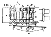
- a locking rod 26 is also incorporated in the body 2 and is arranged parallel to the axis of rotation 10. As shown more specifically in FIGS. Figures 3, 4 and 7 this blocking rod 26 comprises in particular a first profiled end 27 of color which, on the one hand, opens flush with a bore made in the lines external 40 of the thrust reverser, and secondly, perfectly adapts to the aerodynamics of the latter when the latch 1 is in the locking position.
- the locking rod 26 also comprises a second flat end 28 having a diameter greater than that of the locking rod 26.
- this locking rod 26 has a cylindrical constriction 29 between the first end 27 and a conical section 30 whose sectional diameter is increasing towards the second end 28.
- a groove 31 is hollowed out in the the periphery of the locking rod 26 at a distance from the conical section 30, said groove 31 then being separated from the latter by a cylindrical section 32.
- the constriction 29, unlike the conical section 30, is designed so as to be able to cross the section of FIG. 24 of the slot 20, and the groove 31 has a diameter substantially equal to that of the engagement section 22.
- a spring 33 is positioned around the locking rod 26 and has an end bearing against a retaining ring 34 housed in a circular groove made at length of the locking rod 26.
- the latter also comprises a longitudinal window s' extending between its second end 28 and the other end of the spring 33.
- This window 35 is traversed by a stud 37 integral with the body 2 whose function is to prevent any displacement in rotation of the locking rod 26 about its axis, without however preventing it from moving in longitudinal translation.
- a person wishing to manually open the lock 1 must simultaneously press the first end 27 of the locking rod 26 to move the latter in longitudinal translation against the spring 33 until the constriction 29 is in line with the slot 20, and seize the handle 19 to drive the control lever 15 in rotation in the trigonometric direction.
- the control lever 15 performs a dead stroke before driving said axis of rotation 10.
- the locking rod 26 can be released once the slot 20 has been totally disengaged from it. In doing so, the previously compressed spring 33 tends to return to its original shape and therefore forces the locking rod 26 to translate in the opposite direction.
- the first end 27 of the locking rod 26 then projects from the external lines 40 of the associated thrust reverser and can be easily identified by the maintenance personnel. Finally, the person can release the handle 19, the control lever 15 then being obliged to fall back on the locking rod 26 under the action of the torsion spring (not shown) positioned at the axis of rotation 10.
- the engagement section 22 of the slot 20 is finally housed in the groove 31 of the locking rod, and it follows that the latter is deomais locked in longitudinal translation.
- the control lever 15 can rotate clockwise until the constriction 29 is housed in the end section 25.
- the person performing the maneuver can then, on the one hand, release the trigger stop 8 so that the spout 7 of the bolt 3 abuts against the rod 11 of the connecting member 4 under the action of the torsion spring (not shown) placed around the pivot 5, and secondly, release the locking rod 26, the latter then being made movable in longitudinal translation under the action of the spring 33.
- the conical section 30 is finally amen to abut against the end section 25, and it follows that the control lever 15 is completely prevented from rotating.
- the opening of the lock 1 is made in a conventional manner via the piston rod 12 of the hydraulic motor 13 which is able to act on the stop 18 presented by the axis of rotation 10.
- the control lever 15 remains permanently in the locking position, as shown in FIGS. Figures 1 to 3 .
- the end 14 of the axis of rotation 10 can rotate sufficiently, before coming into abutment against the edge of said opening 17 , so that the rod 11 since disengage the spout 7.
- the bolt 3 can then pivoting and the locking member 6 stops obstructing the associated slide in which can slide a rail secured to the moving parts of the thrust reverser.
Landscapes
- Engineering & Computer Science (AREA)
- Chemical & Material Sciences (AREA)
- Combustion & Propulsion (AREA)
- Mechanical Engineering (AREA)
- General Engineering & Computer Science (AREA)
- Lock And Its Accessories (AREA)
- Mechanical Control Devices (AREA)
- Clamps And Clips (AREA)
- Connection Of Motors, Electrical Generators, Mechanical Devices, And The Like (AREA)
Claims (10)
- Verriegelung (1), die dazu bestimmt ist, in eine in der Luftfahrt verwendete Schubumkehrvorrichtung eingesetzt zu werden, wobei diese Verriegelung insbesondere einen Riegel (3) und ein Verbindungsorgan (4) aufweist, an dem ein Steuerhebel (15) befestigt ist, wobei der Riegel unter der Wirkung des Steuerhebels auf das Verbindungsorgan in der Lage ist, abwechselnd von einer Verriegelungsstellung in eine Öffnungsstellung überzugehen, dadurch gekennzeichnet, dass der Steuerhebel einen Schlitz (20) im Wesentlichen lotrecht zur Achse (21) des Steuerhebels aufweist, wobei dieser Schlitz nacheinander einen Einführquerschnitt (22), einen Verengungsquerschnitt (24) und einen verbreiterten Endquerschnitt (25) aufweist, und dass eine in Längstranslation gegen ein elastisches Organ (33) bewegliche Blockierstange (26) parallel zur Drehachse (10) des Steuerhebels angeordnet ist, wobei die Blockierstange mit einer Verjüngung (29) versehen ist, deren Querschnitt geringer als der Verengungsquerschnitt des Schlitzes ist, so dass, wenn diese Verjüngung nach einer Translationsverschiebung der Blockierstange lotrecht zu dem Schlitz positioniert ist, der Steuerhebel abwechselnd von einer Blockierstellung, in der die Blockierstange im Endquerschnitt des Schlitzes gefangen ist, in eine Öffnungsstellung übergehen kann, in der der Schlitz von der Blockierstange gelöst ist.
- Verriegelung (1) nach Anspruch 1, dadurch gekennzeichnet, dass der Endquerschnitt (25) des Schlitzes (20) im Wesentlichen kreisförmig ist, und dass die Verjüngung (29) der Blockierstange (26) sich in der Verlängerung eines kegelförmigen Abschnitts (30) befindet, dessen größter Durchmesser größer als derjenige des Endquerschnitts ist.
- Verriegelung (1) nach einem der Ansprüche 1 oder 2, dadurch gekennzeichnet, dass die Blockierstange (26) eine Rille (31) aufweist, die den Einführquerschnitt (22) des Schlitzes (20) aufnehmen kann, wenn das elastische Organ (33) in der Ruhestellung ist.
- Verriegelung (1) nach einem der Ansprüche 1 bis 3, dadurch gekennzeichnet, dass der Einführquerschnitt (22) im Wesentlichen kreisförmig ist.
- Verriegelung (1) nach einem der Ansprüche 1 bis 4, dadurch gekennzeichnet, dass der Durchmesser des Einführquerschnitts (22) größer ist als derjenige des Endquerschnitts (25).
- Verriegelung (1) nach einem der Ansprüche 1 bis 5, dadurch gekennzeichnet, dass die Blockierstange (26) ein Längsfenster (35) aufweist, dessen Länge mindestens gleich der maximalen Strecke ist, die die Blockierstange in Translationsrichtung durchlaufen kann.
- Verriegelung (1) nach Anspruch 6, dadurch gekennzeichnet, dass das Längsfenster (35) von einem Zapfen (37) durchquert wird, der mit einem ortsfesten Teil der Verriegelung fest verbunden ist.
- Verriegelung (1) nach einem der Ansprüche 1 bis 7, dadurch gekennzeichnet, dass das elastische Organ (33) auf einem Haltering (34) aufliegt, der um die Blockierstange (26) herum positioniert ist.
- Verriegelung (1) nach einem der Ansprüche 1 bis 8, dadurch gekennzeichnet, dass die Blockierstange (26) ein erstes mit Profil versehenes Ende (27) aufweist, das vorgesehen ist, um sich an die Aerodynamik der Außenlinien (40) der zugeordneten Schubumkehrvorrichtung anzupassen.
- Verriegelung (1) nach einem der Ansprüche 1 bis 9, dadurch gekennzeichnet, dass die Blockierstange (26) ein zweites, erweitertes Ende (28) aufweist, das gegen einen ortsfesten Teil der Verriegelung in Anschlag kommen kann.
Applications Claiming Priority (2)
| Application Number | Priority Date | Filing Date | Title |
|---|---|---|---|
| FR0311651A FR2860554B1 (fr) | 2003-10-06 | 2003-10-06 | Verrou pour inverseur de poussee, muni d'un dispositif de blocage |
| PCT/FR2004/002459 WO2005035964A1 (fr) | 2003-10-06 | 2004-09-29 | Verrou pour inverseur de poussee, muni d’un dispositif de bloquage |
Publications (2)
| Publication Number | Publication Date |
|---|---|
| EP1673530A1 EP1673530A1 (de) | 2006-06-28 |
| EP1673530B1 true EP1673530B1 (de) | 2008-11-26 |
Family
ID=34307432
Family Applications (1)
| Application Number | Title | Priority Date | Filing Date |
|---|---|---|---|
| EP20040787478 Expired - Lifetime EP1673530B1 (de) | 2003-10-06 | 2004-09-29 | Schubumkehrerverriegelung mit verriegelungsvorrichtung |
Country Status (11)
| Country | Link |
|---|---|
| US (1) | US20070273159A1 (de) |
| EP (1) | EP1673530B1 (de) |
| CN (1) | CN100424334C (de) |
| AT (1) | ATE415551T1 (de) |
| AU (1) | AU2004279960A1 (de) |
| CA (1) | CA2535327C (de) |
| DE (1) | DE602004018015D1 (de) |
| ES (1) | ES2317059T3 (de) |
| FR (1) | FR2860554B1 (de) |
| RU (1) | RU2324834C2 (de) |
| WO (1) | WO2005035964A1 (de) |
Families Citing this family (13)
| Publication number | Priority date | Publication date | Assignee | Title |
|---|---|---|---|---|
| FR2916425B1 (fr) * | 2007-05-25 | 2009-07-03 | Aircelle Sa | Dispositif de verrouillage d'une partie ouvrante de nacelle de turboreacteur par rapport a une partie fixe,et nacelle equipee d'un tel dispositif |
| JP2011219985A (ja) * | 2010-04-09 | 2011-11-04 | Lalique:Kk | 支保工の部材連結装置 |
| FR2991668B1 (fr) | 2012-06-08 | 2014-06-20 | Aircelle Sa | Dispositif de verrouillage/deverrouillage pour capot monobloc d'inverseur de poussee de nacelle de turboreacteur |
| US9109536B2 (en) | 2013-03-14 | 2015-08-18 | Woodward Hrt, Inc. | Engine thrust reverser lock |
| FR3005302B1 (fr) * | 2013-05-06 | 2015-06-05 | Sagem Defense Securite | Dispositif de commande de la puissance d'un moteur et d'un dispositif inverseur de poussee |
| FR3008741B1 (fr) * | 2013-07-17 | 2017-04-28 | Aircelle Sa | Systeme inverseur de poussee electrique pour nacelle de moteur d'aeronef et nacelle de moteur d'aeronef ainsi equipee |
| KR101522265B1 (ko) * | 2013-10-16 | 2015-05-21 | 엘에스산전 주식회사 | 고압배전반 변압기실 도어 인터록 장치 |
| US20160060911A1 (en) * | 2014-08-29 | 2016-03-03 | Bendix Commercial Vehicle Systems Llc | Apparatus for a Door Locking Module |
| KR101567246B1 (ko) * | 2014-10-17 | 2015-11-06 | 현대자동차주식회사 | 액츄에이터 일체형 푸시 오프너 |
| US11441514B2 (en) | 2018-10-02 | 2022-09-13 | Woodward, Inc. | Tertiary lock |
| US10865738B2 (en) | 2019-02-27 | 2020-12-15 | Woodward, Inc. | Traveling finger lock for an actuator |
| FR3141216A1 (fr) * | 2022-10-24 | 2024-04-26 | Airbus Operations | Turboréacteur double flux comportant des déflecteurs mobiles et un système d’actionnement des déflecteurs |
| US11788490B1 (en) | 2022-12-05 | 2023-10-17 | Woodward, Inc. | Traveling finger lock for an actuator |
Family Cites Families (22)
| Publication number | Priority date | Publication date | Assignee | Title |
|---|---|---|---|---|
| US1355735A (en) * | 1918-08-05 | 1920-10-12 | Crompton Edwin | Combined latch and lock |
| US1942219A (en) * | 1931-05-05 | 1934-01-02 | Segal Samuel | Window lock fastener |
| US2546149A (en) * | 1945-09-19 | 1951-03-27 | Daniel Warren Lewis | Latch |
| US2683053A (en) * | 1950-09-01 | 1954-07-06 | Fred J Russell | Latch operating means |
| US3768847A (en) * | 1971-07-29 | 1973-10-30 | E Buck | Security lock means |
| US3877261A (en) * | 1973-03-12 | 1975-04-15 | Packaging Tech Inc | Keyed fixed door lock |
| FR2488335B1 (fr) * | 1980-08-11 | 1986-01-31 | Snecma | Dispositif detecteur de position d'un inverseur de poussee de turboreacteur et de son verrouillage |
| US4565078A (en) * | 1983-03-04 | 1986-01-21 | Solomon Martin D | Lock assembly |
| GB2161530B (en) * | 1984-07-14 | 1987-10-21 | Ford Motor Co | Electrically controlled door locking system |
| US4922817A (en) * | 1988-07-13 | 1990-05-08 | Pitney Bowes Inc. | Secure shutter locking arrangement for a postage meter |
| US5092637A (en) * | 1990-08-24 | 1992-03-03 | Miller Kermit G | Latch assembly for doors |
| IL103190A (en) * | 1991-09-25 | 1995-06-29 | Messier Bugatti | A security locking device that includes a movable hook |
| FR2683860B1 (fr) * | 1991-11-14 | 1995-04-28 | Hurel Dubois Avions | Installation de securite pour inverseur de poussee a portes equipant un avion et ensemble incorporant une telle installation. |
| US5263347A (en) * | 1992-09-21 | 1993-11-23 | Allbaugh Mark E | Remote control deadlock bolt for cars |
| FR2746838B1 (fr) * | 1996-04-02 | 2004-11-26 | Kiekert Ag | Fermeture de portieres pour vehicules automobiles avec serrure de portiere de vehicule automobile et support de serrure asservi |
| CN1077217C (zh) * | 1996-08-22 | 2002-01-02 | 波音公司 | 反推装置同步轴锁定机构 |
| FR2754314B1 (fr) * | 1996-10-03 | 1999-01-08 | Hispano Suiza Sa | Procede et dispositifs de fermeture des portes d'inverseurs de poussee |
| FR2762875B1 (fr) * | 1997-04-30 | 1999-06-04 | Hispano Suiza Sa | Inverseur de poussee protege en cas de deverrouillage accidentel |
| US6027148A (en) * | 1998-06-12 | 2000-02-22 | Shoemaker; Rodney | Security device for a movable closure and method therefor |
| GB9823697D0 (en) * | 1998-10-30 | 1998-12-23 | Lucas Ind Plc | Deployment inhibiting arrangement for a thrust reverser system |
| FR2830051B1 (fr) * | 2001-09-27 | 2003-11-07 | Hurel Hispano Le Havre | Systeme de verrouillage sur un inverseur de poussee a grilles |
| ATE452265T1 (de) * | 2003-09-12 | 2010-01-15 | Jouko Urpolahti | Verriegelungsbolzen für eine schiebetür oder dergleichen |
-
2003
- 2003-10-06 FR FR0311651A patent/FR2860554B1/fr not_active Expired - Fee Related
-
2004
- 2004-09-29 CN CNB2004800290136A patent/CN100424334C/zh not_active Expired - Fee Related
- 2004-09-29 US US10/571,004 patent/US20070273159A1/en not_active Abandoned
- 2004-09-29 RU RU2006116467A patent/RU2324834C2/ru not_active IP Right Cessation
- 2004-09-29 DE DE200460018015 patent/DE602004018015D1/de not_active Expired - Fee Related
- 2004-09-29 ES ES04787478T patent/ES2317059T3/es not_active Expired - Lifetime
- 2004-09-29 AU AU2004279960A patent/AU2004279960A1/en not_active Abandoned
- 2004-09-29 AT AT04787478T patent/ATE415551T1/de not_active IP Right Cessation
- 2004-09-29 WO PCT/FR2004/002459 patent/WO2005035964A1/fr not_active Ceased
- 2004-09-29 EP EP20040787478 patent/EP1673530B1/de not_active Expired - Lifetime
- 2004-09-29 CA CA 2535327 patent/CA2535327C/fr not_active Expired - Fee Related
Also Published As
| Publication number | Publication date |
|---|---|
| ES2317059T3 (es) | 2009-04-16 |
| RU2006116467A (ru) | 2007-11-27 |
| CN100424334C (zh) | 2008-10-08 |
| FR2860554B1 (fr) | 2005-12-23 |
| DE602004018015D1 (de) | 2009-01-08 |
| FR2860554A1 (fr) | 2005-04-08 |
| WO2005035964A1 (fr) | 2005-04-21 |
| US20070273159A1 (en) | 2007-11-29 |
| RU2324834C2 (ru) | 2008-05-20 |
| AU2004279960A1 (en) | 2005-04-21 |
| CN1864003A (zh) | 2006-11-15 |
| CA2535327A1 (fr) | 2005-04-21 |
| ATE415551T1 (de) | 2008-12-15 |
| EP1673530A1 (de) | 2006-06-28 |
| CA2535327C (fr) | 2009-06-30 |
Similar Documents
| Publication | Publication Date | Title |
|---|---|---|
| EP1673530B1 (de) | Schubumkehrerverriegelung mit verriegelungsvorrichtung | |
| EP2674362B1 (de) | Bolzenschließvorrichtung | |
| EP1644604B1 (de) | Zunge zum verbinden zweier verkleidungen einer flugzeugstruktur | |
| CA2379192C (fr) | Systeme de verrouillage de secours pour porte d'inverseur de poussee | |
| EP2181378B1 (de) | Triebwerksgondel zum einbau in ein flugzeug | |
| CA2918970C (fr) | Dispositif de manoeuvre d'au moins une trappe d'un aeronef comprenant une poignee de commande | |
| EP2446100A1 (de) | Flugzeugriegel mit haken und griff | |
| FR2920170A1 (fr) | Dispositif de verrouillage | |
| EP2431555B1 (de) | Verriegelungsvorrichtung für eine Aussenklappe | |
| EP3877252B1 (de) | Notöffnungsvorrichtung für eine flugzeugtür mit drehfreigabe | |
| EP3980327B1 (de) | Flugzeugtür mit einem hebel zur notöffnung von aussen | |
| EP4166436B1 (de) | Scharnier mit einem entriegelungsorgan | |
| WO2012052659A2 (fr) | Vanne d'isolement commandee a etancheite renforcee. | |
| EP1880072B1 (de) | Mit zwei in längsrichtung versetzten verriegelungspositionen versehenes schloss | |
| FR3075847A1 (fr) | Verrou et trappe comprenant un tel verrou | |
| EP4481212B1 (de) | Karabinerhaken, insbesondere zum klettern und bergsteigen | |
| EP3379009B1 (de) | Stoppanordnung einer öffnungs- und schliesstür eines raums, wie dem laderaum eines fahrzeugs, in ihrer öffnungsposition | |
| FR2866048A1 (fr) | Coffre principal d'une serrure multipoints muni d'une butee de tringle | |
| FR2793276A1 (fr) | Dispositif de fermeture a poignee pivotante | |
| FR2742475A1 (fr) | Verin electromecanique non reversible pour portails ou similaires | |
| FR2891329A1 (fr) | Bielle articulee | |
| FR2808831A1 (fr) | Serrure pour flancs ouvrables de bennes de vehicules | |
| BE698195A (fr) | Dispositif de crosse réglable pour armes à feu | |
| FR2552150A1 (fr) | Loqueteau | |
| FR2829519A1 (fr) | Dispositif de verrouillage pour le maintien d'un ouvrant en position dite de fermeture et ensemble constitue d'un ouvrant associe a un tel dispositif |
Legal Events
| Date | Code | Title | Description |
|---|---|---|---|
| PUAI | Public reference made under article 153(3) epc to a published international application that has entered the european phase |
Free format text: ORIGINAL CODE: 0009012 |
|
| 17P | Request for examination filed |
Effective date: 20060127 |
|
| AK | Designated contracting states |
Kind code of ref document: A1 Designated state(s): AT BE BG CH CY CZ DE DK EE ES FI FR GB GR HU IE IT LI LU MC NL PL PT RO SE SI SK TR |
|
| DAX | Request for extension of the european patent (deleted) | ||
| RIN1 | Information on inventor provided before grant (corrected) |
Inventor name: ROUYER, PASCAL |
|
| GRAP | Despatch of communication of intention to grant a patent |
Free format text: ORIGINAL CODE: EPIDOSNIGR1 |
|
| GRAJ | Information related to disapproval of communication of intention to grant by the applicant or resumption of examination proceedings by the epo deleted |
Free format text: ORIGINAL CODE: EPIDOSDIGR1 |
|
| GRAP | Despatch of communication of intention to grant a patent |
Free format text: ORIGINAL CODE: EPIDOSNIGR1 |
|
| GRAS | Grant fee paid |
Free format text: ORIGINAL CODE: EPIDOSNIGR3 |
|
| GRAA | (expected) grant |
Free format text: ORIGINAL CODE: 0009210 |
|
| AK | Designated contracting states |
Kind code of ref document: B1 Designated state(s): AT BE BG CH CY CZ DE DK EE ES FI FR GB GR HU IE IT LI LU MC NL PL PT RO SE SI SK TR |
|
| REG | Reference to a national code |
Ref country code: GB Ref legal event code: FG4D Free format text: NOT ENGLISH |
|
| REG | Reference to a national code |
Ref country code: CH Ref legal event code: EP |
|
| REG | Reference to a national code |
Ref country code: IE Ref legal event code: FG4D Free format text: LANGUAGE OF EP DOCUMENT: FRENCH |
|
| REF | Corresponds to: |
Ref document number: 602004018015 Country of ref document: DE Date of ref document: 20090108 Kind code of ref document: P |
|
| REG | Reference to a national code |
Ref country code: ES Ref legal event code: FG2A Ref document number: 2317059 Country of ref document: ES Kind code of ref document: T3 |
|
| PG25 | Lapsed in a contracting state [announced via postgrant information from national office to epo] |
Ref country code: AT Free format text: LAPSE BECAUSE OF FAILURE TO SUBMIT A TRANSLATION OF THE DESCRIPTION OR TO PAY THE FEE WITHIN THE PRESCRIBED TIME-LIMIT Effective date: 20081126 |
|
| NLV1 | Nl: lapsed or annulled due to failure to fulfill the requirements of art. 29p and 29m of the patents act | ||
| PG25 | Lapsed in a contracting state [announced via postgrant information from national office to epo] |
Ref country code: NL Free format text: LAPSE BECAUSE OF FAILURE TO SUBMIT A TRANSLATION OF THE DESCRIPTION OR TO PAY THE FEE WITHIN THE PRESCRIBED TIME-LIMIT Effective date: 20081126 Ref country code: FI Free format text: LAPSE BECAUSE OF FAILURE TO SUBMIT A TRANSLATION OF THE DESCRIPTION OR TO PAY THE FEE WITHIN THE PRESCRIBED TIME-LIMIT Effective date: 20081126 Ref country code: PL Free format text: LAPSE BECAUSE OF FAILURE TO SUBMIT A TRANSLATION OF THE DESCRIPTION OR TO PAY THE FEE WITHIN THE PRESCRIBED TIME-LIMIT Effective date: 20081126 Ref country code: SI Free format text: LAPSE BECAUSE OF FAILURE TO SUBMIT A TRANSLATION OF THE DESCRIPTION OR TO PAY THE FEE WITHIN THE PRESCRIBED TIME-LIMIT Effective date: 20081126 |
|
| REG | Reference to a national code |
Ref country code: IE Ref legal event code: FD4D |
|
| PG25 | Lapsed in a contracting state [announced via postgrant information from national office to epo] |
Ref country code: IE Free format text: LAPSE BECAUSE OF FAILURE TO SUBMIT A TRANSLATION OF THE DESCRIPTION OR TO PAY THE FEE WITHIN THE PRESCRIBED TIME-LIMIT Effective date: 20081126 Ref country code: EE Free format text: LAPSE BECAUSE OF FAILURE TO SUBMIT A TRANSLATION OF THE DESCRIPTION OR TO PAY THE FEE WITHIN THE PRESCRIBED TIME-LIMIT Effective date: 20081126 Ref country code: BG Free format text: LAPSE BECAUSE OF FAILURE TO SUBMIT A TRANSLATION OF THE DESCRIPTION OR TO PAY THE FEE WITHIN THE PRESCRIBED TIME-LIMIT Effective date: 20090226 Ref country code: RO Free format text: LAPSE BECAUSE OF FAILURE TO SUBMIT A TRANSLATION OF THE DESCRIPTION OR TO PAY THE FEE WITHIN THE PRESCRIBED TIME-LIMIT Effective date: 20081126 Ref country code: DK Free format text: LAPSE BECAUSE OF FAILURE TO SUBMIT A TRANSLATION OF THE DESCRIPTION OR TO PAY THE FEE WITHIN THE PRESCRIBED TIME-LIMIT Effective date: 20081126 |
|
| PG25 | Lapsed in a contracting state [announced via postgrant information from national office to epo] |
Ref country code: PT Free format text: LAPSE BECAUSE OF FAILURE TO SUBMIT A TRANSLATION OF THE DESCRIPTION OR TO PAY THE FEE WITHIN THE PRESCRIBED TIME-LIMIT Effective date: 20090427 Ref country code: SE Free format text: LAPSE BECAUSE OF FAILURE TO SUBMIT A TRANSLATION OF THE DESCRIPTION OR TO PAY THE FEE WITHIN THE PRESCRIBED TIME-LIMIT Effective date: 20090226 Ref country code: CZ Free format text: LAPSE BECAUSE OF FAILURE TO SUBMIT A TRANSLATION OF THE DESCRIPTION OR TO PAY THE FEE WITHIN THE PRESCRIBED TIME-LIMIT Effective date: 20081126 |
|
| PG25 | Lapsed in a contracting state [announced via postgrant information from national office to epo] |
Ref country code: SK Free format text: LAPSE BECAUSE OF FAILURE TO SUBMIT A TRANSLATION OF THE DESCRIPTION OR TO PAY THE FEE WITHIN THE PRESCRIBED TIME-LIMIT Effective date: 20081126 |
|
| PLBE | No opposition filed within time limit |
Free format text: ORIGINAL CODE: 0009261 |
|
| STAA | Information on the status of an ep patent application or granted ep patent |
Free format text: STATUS: NO OPPOSITION FILED WITHIN TIME LIMIT |
|
| 26N | No opposition filed |
Effective date: 20090827 |
|
| BERE | Be: lapsed |
Owner name: AIRCELLE Effective date: 20090930 |
|
| PG25 | Lapsed in a contracting state [announced via postgrant information from national office to epo] |
Ref country code: MC Free format text: LAPSE BECAUSE OF NON-PAYMENT OF DUE FEES Effective date: 20090930 |
|
| REG | Reference to a national code |
Ref country code: CH Ref legal event code: PL |
|
| GBPC | Gb: european patent ceased through non-payment of renewal fee |
Effective date: 20090929 |
|
| REG | Reference to a national code |
Ref country code: FR Ref legal event code: ST Effective date: 20100531 |
|
| PG25 | Lapsed in a contracting state [announced via postgrant information from national office to epo] |
Ref country code: FR Free format text: LAPSE BECAUSE OF NON-PAYMENT OF DUE FEES Effective date: 20090930 Ref country code: DE Free format text: LAPSE BECAUSE OF NON-PAYMENT OF DUE FEES Effective date: 20100401 |
|
| PG25 | Lapsed in a contracting state [announced via postgrant information from national office to epo] |
Ref country code: BE Free format text: LAPSE BECAUSE OF NON-PAYMENT OF DUE FEES Effective date: 20090930 |
|
| PG25 | Lapsed in a contracting state [announced via postgrant information from national office to epo] |
Ref country code: LI Free format text: LAPSE BECAUSE OF NON-PAYMENT OF DUE FEES Effective date: 20090930 Ref country code: GR Free format text: LAPSE BECAUSE OF FAILURE TO SUBMIT A TRANSLATION OF THE DESCRIPTION OR TO PAY THE FEE WITHIN THE PRESCRIBED TIME-LIMIT Effective date: 20090227 Ref country code: CH Free format text: LAPSE BECAUSE OF NON-PAYMENT OF DUE FEES Effective date: 20090930 |
|
| PG25 | Lapsed in a contracting state [announced via postgrant information from national office to epo] |
Ref country code: GB Free format text: LAPSE BECAUSE OF NON-PAYMENT OF DUE FEES Effective date: 20090929 |
|
| PG25 | Lapsed in a contracting state [announced via postgrant information from national office to epo] |
Ref country code: IT Free format text: LAPSE BECAUSE OF NON-PAYMENT OF DUE FEES Effective date: 20090929 |
|
| PG25 | Lapsed in a contracting state [announced via postgrant information from national office to epo] |
Ref country code: LU Free format text: LAPSE BECAUSE OF NON-PAYMENT OF DUE FEES Effective date: 20090929 |
|
| PG25 | Lapsed in a contracting state [announced via postgrant information from national office to epo] |
Ref country code: HU Free format text: LAPSE BECAUSE OF FAILURE TO SUBMIT A TRANSLATION OF THE DESCRIPTION OR TO PAY THE FEE WITHIN THE PRESCRIBED TIME-LIMIT Effective date: 20090527 |
|
| REG | Reference to a national code |
Ref country code: ES Ref legal event code: FD2A Effective date: 20110711 |
|
| PG25 | Lapsed in a contracting state [announced via postgrant information from national office to epo] |
Ref country code: ES Free format text: LAPSE BECAUSE OF NON-PAYMENT OF DUE FEES Effective date: 20110629 |
|
| PG25 | Lapsed in a contracting state [announced via postgrant information from national office to epo] |
Ref country code: TR Free format text: LAPSE BECAUSE OF FAILURE TO SUBMIT A TRANSLATION OF THE DESCRIPTION OR TO PAY THE FEE WITHIN THE PRESCRIBED TIME-LIMIT Effective date: 20081126 |
|
| PG25 | Lapsed in a contracting state [announced via postgrant information from national office to epo] |
Ref country code: ES Free format text: LAPSE BECAUSE OF NON-PAYMENT OF DUE FEES Effective date: 20090930 Ref country code: CY Free format text: LAPSE BECAUSE OF FAILURE TO SUBMIT A TRANSLATION OF THE DESCRIPTION OR TO PAY THE FEE WITHIN THE PRESCRIBED TIME-LIMIT Effective date: 20081126 |