EP0362054A1 - Gaseinspritzrohre für ein Turbinenstrahl- und Raketentriebwerk - Google Patents
Gaseinspritzrohre für ein Turbinenstrahl- und Raketentriebwerk Download PDFInfo
- Publication number
- EP0362054A1 EP0362054A1 EP89402639A EP89402639A EP0362054A1 EP 0362054 A1 EP0362054 A1 EP 0362054A1 EP 89402639 A EP89402639 A EP 89402639A EP 89402639 A EP89402639 A EP 89402639A EP 0362054 A1 EP0362054 A1 EP 0362054A1
- Authority
- EP
- European Patent Office
- Prior art keywords
- propellant
- turbine
- arms
- cavity
- supplied
- Prior art date
- Legal status (The legal status is an assumption and is not a legal conclusion. Google has not performed a legal analysis and makes no representation as to the accuracy of the status listed.)
- Granted
Links
- 238000002347 injection Methods 0.000 title claims description 45
- 239000007924 injection Substances 0.000 title claims description 45
- 239000007789 gas Substances 0.000 claims abstract description 63
- 239000001257 hydrogen Substances 0.000 claims abstract description 34
- 229910052739 hydrogen Inorganic materials 0.000 claims abstract description 34
- UFHFLCQGNIYNRP-UHFFFAOYSA-N Hydrogen Chemical compound [H][H] UFHFLCQGNIYNRP-UHFFFAOYSA-N 0.000 claims abstract description 31
- 238000011144 upstream manufacturing Methods 0.000 claims abstract description 18
- 238000002485 combustion reaction Methods 0.000 claims abstract description 10
- 239000003380 propellant Substances 0.000 claims description 53
- 210000003462 vein Anatomy 0.000 claims description 24
- QVGXLLKOCUKJST-UHFFFAOYSA-N atomic oxygen Chemical compound [O] QVGXLLKOCUKJST-UHFFFAOYSA-N 0.000 claims description 12
- 239000001301 oxygen Substances 0.000 claims description 12
- 229910052760 oxygen Inorganic materials 0.000 claims description 12
- 239000000203 mixture Substances 0.000 claims description 6
- 230000001172 regenerating effect Effects 0.000 claims description 3
- 239000000446 fuel Substances 0.000 abstract description 9
- 239000000567 combustion gas Substances 0.000 description 5
- 238000010586 diagram Methods 0.000 description 3
- 239000007788 liquid Substances 0.000 description 3
- 230000007704 transition Effects 0.000 description 3
- 230000006835 compression Effects 0.000 description 2
- 238000007906 compression Methods 0.000 description 2
- 150000002431 hydrogen Chemical class 0.000 description 2
- 238000005192 partition Methods 0.000 description 2
- 239000000843 powder Substances 0.000 description 2
- 239000007858 starting material Substances 0.000 description 2
- MYMOFIZGZYHOMD-UHFFFAOYSA-N Dioxygen Chemical compound O=O MYMOFIZGZYHOMD-UHFFFAOYSA-N 0.000 description 1
- 230000006978 adaptation Effects 0.000 description 1
- 238000007664 blowing Methods 0.000 description 1
- 230000000295 complement effect Effects 0.000 description 1
- 230000001143 conditioned effect Effects 0.000 description 1
- 238000001816 cooling Methods 0.000 description 1
- 125000004435 hydrogen atom Chemical group [H]* 0.000 description 1
- 239000000243 solution Substances 0.000 description 1
Images

Classifications
-
- F—MECHANICAL ENGINEERING; LIGHTING; HEATING; WEAPONS; BLASTING
- F02—COMBUSTION ENGINES; HOT-GAS OR COMBUSTION-PRODUCT ENGINE PLANTS
- F02K—JET-PROPULSION PLANTS
- F02K9/00—Rocket-engine plants, i.e. plants carrying both fuel and oxidant therefor; Control thereof
- F02K9/42—Rocket-engine plants, i.e. plants carrying both fuel and oxidant therefor; Control thereof using liquid or gaseous propellants
- F02K9/44—Feeding propellants
- F02K9/52—Injectors
-
- F—MECHANICAL ENGINEERING; LIGHTING; HEATING; WEAPONS; BLASTING
- F02—COMBUSTION ENGINES; HOT-GAS OR COMBUSTION-PRODUCT ENGINE PLANTS
- F02K—JET-PROPULSION PLANTS
- F02K3/00—Plants including a gas turbine driving a compressor or a ducted fan
- F02K3/08—Plants including a gas turbine driving a compressor or a ducted fan with supplementary heating of the working fluid; Control thereof
- F02K3/10—Plants including a gas turbine driving a compressor or a ducted fan with supplementary heating of the working fluid; Control thereof by after-burners
-
- F—MECHANICAL ENGINEERING; LIGHTING; HEATING; WEAPONS; BLASTING
- F02—COMBUSTION ENGINES; HOT-GAS OR COMBUSTION-PRODUCT ENGINE PLANTS
- F02K—JET-PROPULSION PLANTS
- F02K7/00—Plants in which the working fluid is used in a jet only, i.e. the plants not having a turbine or other engine driving a compressor or a ducted fan; Control thereof
- F02K7/10—Plants in which the working fluid is used in a jet only, i.e. the plants not having a turbine or other engine driving a compressor or a ducted fan; Control thereof characterised by having ram-action compression, i.e. aero-thermo-dynamic-ducts or ram-jet engines
- F02K7/16—Composite ram-jet/turbo-jet engines
-
- F—MECHANICAL ENGINEERING; LIGHTING; HEATING; WEAPONS; BLASTING
- F02—COMBUSTION ENGINES; HOT-GAS OR COMBUSTION-PRODUCT ENGINE PLANTS
- F02K—JET-PROPULSION PLANTS
- F02K9/00—Rocket-engine plants, i.e. plants carrying both fuel and oxidant therefor; Control thereof
- F02K9/74—Rocket-engine plants, i.e. plants carrying both fuel and oxidant therefor; Control thereof combined with another jet-propulsion plant
- F02K9/78—Rocket-engine plants, i.e. plants carrying both fuel and oxidant therefor; Control thereof combined with another jet-propulsion plant with an air-breathing jet-propulsion plant
Definitions
- the subject of the present invention is a combined turbo-stato-rocket propellant with an expander cycle or with an external gas generator comprising an improved device for injecting turbine gases and / or exhaust gases from the gas generator, in the air stream for turbo-rocket and ramjet operations.
- a propellant was used using liquid hydrogen and liquid oxygen for fuels and using three operating modes.
- the thruster From start-up and up to a Mach number of 5 and from altitude 0 up to around 20 km, the thruster operates in turbo expander or turbo rocket mode (in the case of a gas generator thruster) exhaust gases from the turbine, rich in hydrogen being injected into the air stream, previously compressed by the compressor, to be burned and ejected in a convergent-divergent nozzle.
- turbo expander or turbo rocket mode in the case of a gas generator thruster
- the propellant operates in ramjet mode, the air entering the vein then not being compressed apart from simple dynamic compression in the inlet of air, the compressor put into autorotation with a pressure ratio close to unity.
- the fuel injected into the vein is on the one hand hydrogen coming directly from the regenerative circuit (heat exchanger on the wall of the nozzle), on the other hand hydrogen coming from this same circuit which was then expanded in the LH2 turbopump turbine of the hydraulic circuit.
- the gases injected into the combustion chamber of the ramjet consist of hydrogen directly from the regenerative circuit and by the combustion gases of the gas generator, after partial use of the energy of these gases for driving the turbopumps at LH2 and LOx.
- Another object of the invention is of course to provide the modes of supply of such an injection device according to the different possible modes of operation of the propellant. Therefore a combined turbo-stato-rocket propellant comprising a propellant turbine disposed in a central body of the propellant, said central body being surrounded by an annular vein comprising upstream an air compressor driven by the turbine, the gases of exhaust of the turbine being injected into the stream of compressed air to be mixed therewith and to be burned in a combustion chamber, the invention relates to a device for injecting gases into the stream consisting of radial arms comprising an aerodynamic profile, regularly distributed between an internal ring and an external ring of the vein, said radial arms comprising at least one radial cavity supplied from the central body of the propellant by the exhaust gases from the turbine, and the arms radial further comprising on their lower surface of the injection holes of said exhaust gas into the compressed air stream.
- the radial arms of the injection device have two internal cavities, each having injection ports on the lower surface of the arms, and the cavity disposed upstream of the airfoil is that capable of receiving the exhaust gases from the turbine in operating mode of the propellant in turbofuse, while the cavity disposed downstream of the aerodynamic profile of the arms is capable of being supplied in operating mode of the propellant as a ramjet, through the outer ring of the vein, in propellants or in gases generated by an auxiliary gas generator, said propellants or gases being taken downstream of the turbines of the propellant turbopumps of the propellant supply circuit or coming directly from the nozzle exchanger.
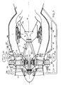
- FIG. 1 has been shown a combined turbo-stato-rocket propellant according to the objectives of the present invention and which includes improvements.
- the external environment of the propellant (supply circuits) has been shown for an "expander” supply cycle corresponding to FIG. 4 for purposes of exemplification.
- Adaptation to the "gas generator” circuit according to FIG. 5 does not in any way modify the internal structure of the propellant, only the power supplies being modified.
- the propellant comprises an annular stream 1 formed between a central body 2 and an external casing 3. Upstream of the stream is arranged an air compressor 4 here formed of two counter-rotating stages 4a, 4b connected by concentric shafts 5a, 5b to two counter-rotating and nested rotors 6a, 6b, of a power turbine 6, arranged inside the central body downstream of the compressor 4.
- an air compressor 4 here formed of two counter-rotating stages 4a, 4b connected by concentric shafts 5a, 5b to two counter-rotating and nested rotors 6a, 6b, of a power turbine 6, arranged inside the central body downstream of the compressor 4.
- a rocket motor 9 In the downstream part of the body is disposed a rocket motor 9, the propellant gases of which are ejected into a nozzle 10 formed of a first diverging section 10a, of a second removable section 10b and a third fixed divergent section 10c.
- the annular stream 1 used for the turbo and stato propulsion modes opens into the nozzle 10 at the location occupied in rocket mode by the removable section 10b.
- a device 11 for retracting the section 10b of the divergence of the rocket engine 9, and for installing a means for varying the section of the nozzle neck is disposed inside the central body 2. It allows after retraction section 10b to set up in the vein of flaps 12 in the shape of a petal whose axial position will vary the section of the neck of the converging convergent nozzle according to the operating mode turbo or stato.
- the power turbine 6 is supplied with gas under pressure from an external supply circuit (which will be detailed below with reference to FIGS. 4 and 5), the turbine gases reaching the upstream part of the turbine by means of 'an intake manifold 7 passing through structural arms 8 which connect and maintain the central body 2 to the external casing 3.
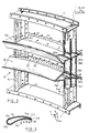
- each arm 14 has an aerodynamic profile with a leading edge 14a, a trailing edge 14b, an upper surface 14c and a lower surface 14d. As seen in section AA of Figure 3 each arm 14 is hollow and is separated into two cavities, one upstream 14e and the other downstream 14f by a partition 14g.
- the cavity 14e passes through the internal ferrule 15 of the injection device, in order to be supplied by the gases coming from the turbine 6.
- the cavity 14e has, on its most downstream part, injection orifices 16 drilled in the wall of lower surface 14d of the arms 14. Two rows of orifices 16 can for example be drilled over the entire height of the arms 14.
- the cavity 14e is closed at its radially external end by the external ferrule 17 of the device 13.
- the downstream cavity 14f for its part, crosses the ferrule 17 to be supplied in stato and turbo modes by the supply circuit and its radially internal end is closed by the internal ferrule 15.
- Injection orifices 18 are drilled on the wall lower surface 14d on the downstream part of the cavity 14f.
- the injection device 13 also comprises two manifold rings 19, 20 also having an aerodynamic profile.
- the two collector rings 19 and 20 have a symmetrical and constant aerodynamic profile over their entire circumferential length according to the conventional laws of injection.
- the ring 19, disposed substantially at one third of the radial height of the arms 14, has its lower surface facing the inside of the vein while the ring 20 located at the two third of the radial height of the vein has its lower surface facing outward from the vein.
- This structure has the advantage of creating a vacuum between the rings and improving the air / fuel mixture.
- the two rings have an upstream cavity 19a, 20a which opens into the upstream cavities 14e of each of the radial arms 14 and a downstream cavity 19b, 20b which opens into the downstream cavities 14f of the arms 14.
- Injection orifices 21,22 are drilled in the lower and upper surfaces of the rings 19,20 respectively near the partition 19c, 20c which separates the cavities 19a, 19b and 20a, 20b, for the injection into the vein of the gases distributed by the upstream cavities 19a, 20a of the rings and near the trailing edge of the ring for the injection of gases distributed by the downstream cavities 19b, 20b.
- FIG 4 there is shown the hydraulic circuit of a combined propellant turbostatofusée cycle called expander.
- the only propellant used in stato or turbo mode is hydrogen.
- the liquid hydrogen coming from a storage tank 101 is pumped by means of a turbopump 102 then is brought by a pipe 103 and two valves 104, 105 on the one hand to a heat exchanger 106 placed on the wall of the combustion and on the other hand to a pipe 107 which, provided with a non-return valve 108 will supply the turbines of two turbopumps, one 102 already mentioned and the other 109 intended for the oxygen supply of the engine- rocket 9.
- a valve 110 is used to isolate the 109 turbopump of the circuit when needed, ie in turbo and stato modes.
- the hydrogen which has just been expanded and which has therefore used part of its energy is separated into two circuits, one of which, 111, controlled by a valve 112 authorizes the injection of hydrogen into the cavity 14f of the radial arms and 19b, 20b of the rings of the injection device 13, and the other 113 of which branches out into two parts 114 and 7 each controlled by a valve 115, 116.
- the circuit 7 supplies the power turbine 6 while circuit 114 will supply the rocket engine 9 in rocket mode.
- the turbine outlet 6 is connected to the internal part of the injection device 13 through the ferrule 15.
- the hydrogen at the outlet of said exchanger where it has taken calories and increased its enthalpy, is used to supply two circuits, one 117 controlled by a valve 118 allows the injection in hydrogen mode of the hydrogen into the cavities 14f of the radial arms, and 19b, 20b of the manifold rings of the injection device 13, while the other circuit 119 will join the pipe 107 downstream of the valve check valve 108 to provide the energy necessary for driving the turbopump 102 in turbo and stato modes.
- the turbopumps 102 and 109 are driven by the hydrogen circulating in the pipe 107 which has taken up calories in a heat exchanger 90 located on the wall of the rocket chamber 9.
- the supply circuit in propellants includes an oxygen tank 120 which can be isolated by a valve 121 and whose outlet 122 is connected to the pump of the turbopump 109 whose outlet flow feeds, through a pipe 123 in rocket mode only, the rocket motor 9.
- the different operating modes are conditioned by the opening / closing of the different valves mentioned above in order to supply or interrupt this or that other part of the circuit, which can be summarized by the following table in which the different modes are indicated with the opening (0) / closing (F) state of each valve opposite: VALVES OPERATING MODE 104 105 110 112 115 116 118 121 TURBO-EXPANDER 0 F F F F 0 0 F STATO-REACTOR 0 F F 0 F F 0 F ROCKET F 0 0 F 0 F F F 0;
- the transition to ramjet mode is carried out by isolating the turbine 6 by closing the valve 116 and simultaneously opening the valve 112 so that the hydrogen leaving the turbine of the turbopump 102 is injected by means of the pipe 111 in the cavity 14f of the arms 14 and in the corresponding cavities 19b, 20b of the collector rings.
- the valves 104, 118 being open, the part of the flow of hydrogen leaving the exchanger 106, which is not used in the turbopump 102 is injected directly by means of the pipe 117 into the cavity 14f of the trailing edge of the arms.
- the entire hydrogen injection in stato mode is therefore provided by the trailing edge cavities 14f, 19b, 20b.
- the transition to rocket mode is carried out by closing the valve 104 and simultaneously opening the valves 105, 110, 115 and 121.
- the hydrogen coming from the pump 102 feeds by 107 the turbines of the two turbopumps 102 and 109, then by 113 and 114 is injected into the chamber of the rocket engine 9.
- the oxygen pumped by 109 is brought via line 123 to the chamber of the rocket engine 9.
- a propellant comprising the injection device according to the invention can be used with a complementary gas generator for driving the turbine 6 and hydrogen and oxygen turbopumps.
- the liquid hydrogen coming from the tank 201 is pumped by the pump of the turbopump 202 then is brought by a pipe 203 to two valves in parallel 204 and 205. Downstream of the valve 204 is arranged the nozzle heat exchanger 206 in output from which the hydrogen circuit separates into two parts, the first 207 directly supplying the gas generator 208 with hydrogen (previously vaporized in the exchanger 206), while the second part 209, controlled by a valve 210 allows in modes turbo and stato fuel injection in the downstream cavities 14f of the radial arms and 19b, 20b of the manifold rings.
- valve 205 also separates into two parts.
- a first part 211 will supply H2 to the chamber of the rocket engine 9 while the second tube 212 comprising a non-return valve 213 will join the tube 207 to provide additional hydrogen flow to the gas generator 208.
- the oxygen circuit comprises a storage tank 214 from which oxygen is pumped by a turbopump 215. At the outlet of said pump, the oxygen circuit is divided into two: a part 216 is used for the permanent supply of oxygen from the gas generator 208 while the other part 217 controlled by a valve 218, will serve in rocket mode to supply the rocket engine chamber 9.
- the combustion gases from the generator 208 serve on the one hand to supply continuously, by a pipe 219, the turbines of the two turbopumps 202 and 215 and, on the other hand to supply by a line 220, controlled by a valve 221, the turbine 6, the ejection gases of which will be injected in the cavity 14e of the radial arms 14.
- the opening (0) / Closing (F) states of the different valves according to the modes of use are summarized in the following table: VALVES OPERATING MODES 204 205 210 218 221 222 223 TURBO-FUSEE 0 F 0 F 0 0 F STATO-FUSEE 0 F 0 F F 0 F ROCKET F 0 F 0 F F 0
- the thruster works as follows:
- LH2 and LOx are pressurized by the turbopumps then, the valve 204 being open and the valve 205 closed, the entire flow rate of LH2 is heated and vaporized in the nozzle exchanger 206 then it is brought to the gas generator 208 by 207 while the oxygen is brought there by the line 216.
- the combustion gases from the generator 208 are used simultaneously to drive the turbopumps 202 and 215 and the power turbine 6 which drives the compressor 4, before being injected into the vein by means of the injection device 13 where these gases, clearly in excess in H2, burn again in contact with compressed atmospheric air and escape through the nozzle with adjustable section giving the necessary thrust to the aircraft.
- the gas flow used for driving the turbines 202 and 215 is injected into the stream 1 by the device 13 at the outlet of which it mixes with the compressed air and the gases of the generator 208 coming from the turbine 6 to be burned in the combustion chamber.
- stato-reactor mode In stato-reactor mode, the valves 204 and 210 being open and the valves 205 and 221 closed, part of the hydrogen flow rate is brought directly to the injection device 13 by the line 209 and the cavities 14f, 19b, 20b of this device while the other part of the hydrogen flow is burned in the gas generator 208 as before.
- the advantage of the injection device 13 is that it allows intimate mixing of vaporized hydrogen from 209 and the combustion gases from generator 208.
- valves 204, 210, 221 and 222 are closed.
- the flow of hydrogen is brought partly to the rocket 9 by the line 211 and partly to the gas generator 208 by the lines 212 and 207, while the oxygen pumped by 215 is brought to the gas generator by 216 and to the rocket motor 9 through line 217 through valve 218 open.
- the structure of the injection device 13 ensures good fuel injection in each of the operating modes and allows the transition between the two operating modes since the downstream cavities 14f, 19b, 20b remain supplied during the two turbo and stato operating modes.
- the arrangement of the collector rings (in the embodiment shown in FIG. 2), whose curvatures are opposite and whose trailing edges are arranged downstream of those of the arms 14, makes it possible to ensure good attachment. of the flame on the trailing edge of the rings 19.20 both in the turbo mode and in the stato mode, as well as a good distribution of the air / gas mixture over the entire radial height of the vein 1.
- the injection device 13 according to the invention has just been described integrated into a combined turbo-stato-rocket propeller of a particular type, but it is quite obvious that it could be used with combined turbo-stato propellers which would not include the rocket motor 9 described here.
Landscapes
- Engineering & Computer Science (AREA)
- Chemical & Material Sciences (AREA)
- Combustion & Propulsion (AREA)
- Mechanical Engineering (AREA)
- General Engineering & Computer Science (AREA)
- Jet Pumps And Other Pumps (AREA)
- Supercharger (AREA)
Applications Claiming Priority (2)
| Application Number | Priority Date | Filing Date | Title |
|---|---|---|---|
| FR8812645A FR2637018A1 (fr) | 1988-09-28 | 1988-09-28 | Dispositif d'injection de gaz pour propulseur combine turbo-stato-fusee |
| FR8812645 | 1988-09-28 |
Publications (2)
| Publication Number | Publication Date |
|---|---|
| EP0362054A1 true EP0362054A1 (de) | 1990-04-04 |
| EP0362054B1 EP0362054B1 (de) | 1992-04-15 |
Family
ID=9370466
Family Applications (1)
| Application Number | Title | Priority Date | Filing Date |
|---|---|---|---|
| EP89402639A Expired - Lifetime EP0362054B1 (de) | 1988-09-28 | 1989-09-27 | Gaseinspritzrohre für ein Turbinenstrahl- und Raketentriebwerk |
Country Status (4)
| Country | Link |
|---|---|
| EP (1) | EP0362054B1 (de) |
| JP (1) | JPH0672575B2 (de) |
| DE (1) | DE68901240D1 (de) |
| FR (1) | FR2637018A1 (de) |
Cited By (3)
| Publication number | Priority date | Publication date | Assignee | Title |
|---|---|---|---|---|
| EP0979974A3 (de) * | 1998-08-11 | 2002-06-05 | Allison Advanced Development Company | Methode und Einrichtung zum Einspritzen von Kraftstoff in einer Gasturbine |
| FR2967725A1 (fr) * | 2010-11-23 | 2012-05-25 | Snecma | Propulseur combine turboreacteur et statoreacteur |
| WO2024051938A1 (en) * | 2022-09-08 | 2024-03-14 | Destinus Sa | Air turborocket with an optimized air-mixer |
Families Citing this family (4)
| Publication number | Priority date | Publication date | Assignee | Title |
|---|---|---|---|---|
| JP4256820B2 (ja) | 2004-06-29 | 2009-04-22 | 三菱重工業株式会社 | デトネーションエンジンおよびこれを備えた飛行体 |
| US8763400B2 (en) * | 2009-08-04 | 2014-07-01 | General Electric Company | Aerodynamic pylon fuel injector system for combustors |
| JP5113230B2 (ja) * | 2010-01-04 | 2013-01-09 | 貴之 伊東 | ロケット発電エンジン及びロケット発電ファンエンジン |
| US11905914B2 (en) | 2022-02-11 | 2024-02-20 | Rtx Corporation | Liquid hydrogen-liquid oxygen fueled powerplant |
Citations (6)
| Publication number | Priority date | Publication date | Assignee | Title |
|---|---|---|---|---|
| US2482505A (en) * | 1947-09-13 | 1949-09-20 | Wright Aeronautieal Corp | Mechanism providing a ram jet engine with a pilot flame and with a drive for its auxiliary equipment |
| US3172253A (en) * | 1959-01-02 | 1965-03-09 | Garrett Corp | Combination turbo and ramjet propulsion apparatus |
| US3286473A (en) * | 1963-06-26 | 1966-11-22 | North American Aviation Inc | Fixed injector and turbopump assembly |
| US3413810A (en) * | 1965-05-15 | 1968-12-03 | Bolkow Gmbh | Fuel injection device for liquid fuel rocket engines |
| DE1923150A1 (de) * | 1968-05-08 | 1970-01-15 | Man Turbo Gmbh | Zweistromturbinenstrahltriebwerk |
| DE3617915C1 (de) * | 1986-05-28 | 1987-09-17 | Messerschmitt Boelkow Blohm | Kombinationsantrieb |
Family Cites Families (1)
| Publication number | Priority date | Publication date | Assignee | Title |
|---|---|---|---|---|
| DE3738703A1 (de) * | 1987-05-27 | 1988-12-08 | Mtu Muenchen Gmbh | Kombiniertes, umschaltbares strahltriebwerk zum antrieb von flugzeugen und raumfahrzeugen |
-
1988
- 1988-09-28 FR FR8812645A patent/FR2637018A1/fr active Pending
-
1989
- 1989-09-27 EP EP89402639A patent/EP0362054B1/de not_active Expired - Lifetime
- 1989-09-27 DE DE8989402639T patent/DE68901240D1/de not_active Expired - Lifetime
- 1989-09-28 JP JP25373089A patent/JPH0672575B2/ja not_active Expired - Fee Related
Patent Citations (6)
| Publication number | Priority date | Publication date | Assignee | Title |
|---|---|---|---|---|
| US2482505A (en) * | 1947-09-13 | 1949-09-20 | Wright Aeronautieal Corp | Mechanism providing a ram jet engine with a pilot flame and with a drive for its auxiliary equipment |
| US3172253A (en) * | 1959-01-02 | 1965-03-09 | Garrett Corp | Combination turbo and ramjet propulsion apparatus |
| US3286473A (en) * | 1963-06-26 | 1966-11-22 | North American Aviation Inc | Fixed injector and turbopump assembly |
| US3413810A (en) * | 1965-05-15 | 1968-12-03 | Bolkow Gmbh | Fuel injection device for liquid fuel rocket engines |
| DE1923150A1 (de) * | 1968-05-08 | 1970-01-15 | Man Turbo Gmbh | Zweistromturbinenstrahltriebwerk |
| DE3617915C1 (de) * | 1986-05-28 | 1987-09-17 | Messerschmitt Boelkow Blohm | Kombinationsantrieb |
Cited By (6)
| Publication number | Priority date | Publication date | Assignee | Title |
|---|---|---|---|---|
| EP0979974A3 (de) * | 1998-08-11 | 2002-06-05 | Allison Advanced Development Company | Methode und Einrichtung zum Einspritzen von Kraftstoff in einer Gasturbine |
| FR2967725A1 (fr) * | 2010-11-23 | 2012-05-25 | Snecma | Propulseur combine turboreacteur et statoreacteur |
| WO2012069729A1 (fr) * | 2010-11-23 | 2012-05-31 | Snecma | Propulseur combine turboreacteur et statoreacteur |
| RU2576403C2 (ru) * | 2010-11-23 | 2016-03-10 | Снекма | Комбинированный турбопрямоточный реактивный двигатель |
| US9422889B2 (en) | 2010-11-23 | 2016-08-23 | Snecma | Combined turbojet and ramjet engine |
| WO2024051938A1 (en) * | 2022-09-08 | 2024-03-14 | Destinus Sa | Air turborocket with an optimized air-mixer |
Also Published As
| Publication number | Publication date |
|---|---|
| JPH0672575B2 (ja) | 1994-09-14 |
| FR2637018A1 (fr) | 1990-03-30 |
| JPH02130249A (ja) | 1990-05-18 |
| EP0362054B1 (de) | 1992-04-15 |
| DE68901240D1 (de) | 1992-05-21 |
Similar Documents
| Publication | Publication Date | Title |
|---|---|---|
| EP0403372B1 (de) | Turbostrahl- und Raketenkombinationstriebwerk | |
| EP2643579B1 (de) | Kombination aus einem turboluftstrahltriebwerk und staustrahltriebwerk | |
| EP0333585B1 (de) | Kombinationstriebwerk, Rakete mit luftatmendem Turbinenstrahltriebwerk | |
| US5052176A (en) | Combination turbojet-ramjet-rocket propulsion system | |
| US6668542B2 (en) | Pulse detonation bypass engine propulsion pod | |
| FR2599428A1 (fr) | Dispositif de propulsion combine pour aeronefs, en particulier pour avions spatiaux. | |
| US3216191A (en) | Thrust chamber and turbopump assembly | |
| WO2012156595A1 (fr) | Statoréacteur à chambre de détonation, engin volant comprenant un tel statoréacteur. | |
| FR2660736A1 (fr) | Assemblage de combustion etagee pauvre. | |
| US4901525A (en) | Booster-sustainer rocket engine and method | |
| FR2987081A1 (fr) | Ensemble et procede propulsifs | |
| EP0362052B1 (de) | Düsenkonstruktion für einen Kombinationsantrieb (Turbo-Staustrahl-Rakete) | |
| WO2021074553A1 (fr) | Propulseur hybride pour vehicule spatial | |
| US3279187A (en) | Rocket-ramjet propulsion engine | |
| FR2701293A1 (fr) | Moteur combiné intégrant les modes éjecteur à air turbocomprimé refroidi ou liquéfié statoréacteur et super-statoréacteur. | |
| EP0362054B1 (de) | Gaseinspritzrohre für ein Turbinenstrahl- und Raketentriebwerk | |
| EP0362053B1 (de) | Konstruktion eines Kombinationsantriebs für zwei Funktionstypen | |
| FR2687433A1 (fr) | Propulseur a composants inverses, a alimentation modulee. | |
| US11846251B1 (en) | Liquid rocket engine booster engine with combustion gas fuel source | |
| WO2014191637A4 (fr) | Dispositif de propulsion de type aerobie et anaerobie a fonctionnement en regime permanent de type combine et simultane | |
| FR2615903A1 (fr) | Moteur thermique aerobie, notamment pour la propulsion d'avions hypersoniques | |
| US5105615A (en) | Turbojet engine with at least one axially movable arranged sliding valve | |
| US3091082A (en) | Combination turbojet and ramjet engine | |
| CA2262059C (fr) | Moteur mixte susceptible de mettre en oeuvre au moins un mode statoreacteur et un mode superstatoreacteur | |
| JP3005676B2 (ja) | ターボジェットエンジン及び該ターボジェットエンジンを備えた複合エンジン |
Legal Events
| Date | Code | Title | Description |
|---|---|---|---|
| PUAI | Public reference made under article 153(3) epc to a published international application that has entered the european phase |
Free format text: ORIGINAL CODE: 0009012 |
|
| 17P | Request for examination filed |
Effective date: 19891011 |
|
| AK | Designated contracting states |
Kind code of ref document: A1 Designated state(s): DE FR GB IT |
|
| 17Q | First examination report despatched |
Effective date: 19910326 |
|
| GRAA | (expected) grant |
Free format text: ORIGINAL CODE: 0009210 |
|
| ITF | It: translation for a ep patent filed | ||
| AK | Designated contracting states |
Kind code of ref document: B1 Designated state(s): DE FR GB IT |
|
| REF | Corresponds to: |
Ref document number: 68901240 Country of ref document: DE Date of ref document: 19920521 |
|
| GBT | Gb: translation of ep patent filed (gb section 77(6)(a)/1977) | ||
| PLBE | No opposition filed within time limit |
Free format text: ORIGINAL CODE: 0009261 |
|
| STAA | Information on the status of an ep patent application or granted ep patent |
Free format text: STATUS: NO OPPOSITION FILED WITHIN TIME LIMIT |
|
| 26N | No opposition filed | ||
| REG | Reference to a national code |
Ref country code: GB Ref legal event code: IF02 |
|
| REG | Reference to a national code |
Ref country code: FR Ref legal event code: TP Ref country code: FR Ref legal event code: CD |
|
| PGFP | Annual fee paid to national office [announced via postgrant information from national office to epo] |
Ref country code: GB Payment date: 20040826 Year of fee payment: 16 Ref country code: DE Payment date: 20040826 Year of fee payment: 16 |
|
| PGFP | Annual fee paid to national office [announced via postgrant information from national office to epo] |
Ref country code: FR Payment date: 20040827 Year of fee payment: 16 |
|
| PG25 | Lapsed in a contracting state [announced via postgrant information from national office to epo] |
Ref country code: IT Free format text: LAPSE BECAUSE OF NON-PAYMENT OF DUE FEES;WARNING: LAPSES OF ITALIAN PATENTS WITH EFFECTIVE DATE BEFORE 2007 MAY HAVE OCCURRED AT ANY TIME BEFORE 2007. THE CORRECT EFFECTIVE DATE MAY BE DIFFERENT FROM THE ONE RECORDED. Effective date: 20050927 Ref country code: GB Free format text: LAPSE BECAUSE OF NON-PAYMENT OF DUE FEES Effective date: 20050927 |
|
| PG25 | Lapsed in a contracting state [announced via postgrant information from national office to epo] |
Ref country code: DE Free format text: LAPSE BECAUSE OF NON-PAYMENT OF DUE FEES Effective date: 20060401 |
|
| GBPC | Gb: european patent ceased through non-payment of renewal fee |
Effective date: 20050927 |
|
| PG25 | Lapsed in a contracting state [announced via postgrant information from national office to epo] |
Ref country code: FR Free format text: LAPSE BECAUSE OF NON-PAYMENT OF DUE FEES Effective date: 20060531 |
|
| REG | Reference to a national code |
Ref country code: FR Ref legal event code: ST Effective date: 20060531 |