EP0362206B1 - Transmission hydraulique - Google Patents
Transmission hydraulique Download PDFInfo
- Publication number
- EP0362206B1 EP0362206B1 EP88902481A EP88902481A EP0362206B1 EP 0362206 B1 EP0362206 B1 EP 0362206B1 EP 88902481 A EP88902481 A EP 88902481A EP 88902481 A EP88902481 A EP 88902481A EP 0362206 B1 EP0362206 B1 EP 0362206B1
- Authority
- EP
- European Patent Office
- Prior art keywords
- working
- reversing valve
- working cylinder
- lines
- valve
- Prior art date
- Legal status (The legal status is an assumption and is not a legal conclusion. Google has not performed a legal analysis and makes no representation as to the accuracy of the status listed.)
- Expired - Lifetime
Links
- 239000012530 fluid Substances 0.000 claims abstract description 31
- 238000001816 cooling Methods 0.000 claims description 12
- 238000011010 flushing procedure Methods 0.000 claims description 10
- 230000003213 activating effect Effects 0.000 claims 2
- 230000007935 neutral effect Effects 0.000 claims 1
- 239000010720 hydraulic oil Substances 0.000 description 12
- 238000000034 method Methods 0.000 description 3
- 238000010276 construction Methods 0.000 description 2
- 238000011161 development Methods 0.000 description 2
- 230000018109 developmental process Effects 0.000 description 2
- 230000002411 adverse Effects 0.000 description 1
- 238000009529 body temperature measurement Methods 0.000 description 1
- 238000013461 design Methods 0.000 description 1
- 238000010586 diagram Methods 0.000 description 1
- 230000005284 excitation Effects 0.000 description 1
- 238000010438 heat treatment Methods 0.000 description 1
- 230000000977 initiatory effect Effects 0.000 description 1
- 230000007774 longterm Effects 0.000 description 1
- 238000012986 modification Methods 0.000 description 1
- 230000004048 modification Effects 0.000 description 1
- 230000000737 periodic effect Effects 0.000 description 1
- 238000009420 retrofitting Methods 0.000 description 1
- 230000035939 shock Effects 0.000 description 1
Images

Classifications
-
- F—MECHANICAL ENGINEERING; LIGHTING; HEATING; WEAPONS; BLASTING
- F15—FLUID-PRESSURE ACTUATORS; HYDRAULICS OR PNEUMATICS IN GENERAL
- F15B—SYSTEMS ACTING BY MEANS OF FLUIDS IN GENERAL; FLUID-PRESSURE ACTUATORS, e.g. SERVOMOTORS; DETAILS OF FLUID-PRESSURE SYSTEMS, NOT OTHERWISE PROVIDED FOR
- F15B21/00—Common features of fluid actuator systems; Fluid-pressure actuator systems or details thereof, not covered by any other group of this subclass
- F15B21/04—Special measures taken in connection with the properties of the fluid
- F15B21/041—Removal or measurement of solid or liquid contamination, e.g. filtering
-
- F—MECHANICAL ENGINEERING; LIGHTING; HEATING; WEAPONS; BLASTING
- F15—FLUID-PRESSURE ACTUATORS; HYDRAULICS OR PNEUMATICS IN GENERAL
- F15B—SYSTEMS ACTING BY MEANS OF FLUIDS IN GENERAL; FLUID-PRESSURE ACTUATORS, e.g. SERVOMOTORS; DETAILS OF FLUID-PRESSURE SYSTEMS, NOT OTHERWISE PROVIDED FOR
- F15B21/00—Common features of fluid actuator systems; Fluid-pressure actuator systems or details thereof, not covered by any other group of this subclass
- F15B21/04—Special measures taken in connection with the properties of the fluid
- F15B21/042—Controlling the temperature of the fluid
- F15B21/0423—Cooling
-
- F—MECHANICAL ENGINEERING; LIGHTING; HEATING; WEAPONS; BLASTING
- F15—FLUID-PRESSURE ACTUATORS; HYDRAULICS OR PNEUMATICS IN GENERAL
- F15B—SYSTEMS ACTING BY MEANS OF FLUIDS IN GENERAL; FLUID-PRESSURE ACTUATORS, e.g. SERVOMOTORS; DETAILS OF FLUID-PRESSURE SYSTEMS, NOT OTHERWISE PROVIDED FOR
- F15B2211/00—Circuits for servomotor systems
- F15B2211/30—Directional control
- F15B2211/305—Directional control characterised by the type of valves
- F15B2211/3056—Assemblies of multiple valves
- F15B2211/30565—Assemblies of multiple valves having multiple valves for a single output member, e.g. for creating higher valve function by use of multiple valves like two 2/2-valves replacing a 5/3-valve
- F15B2211/3058—Assemblies of multiple valves having multiple valves for a single output member, e.g. for creating higher valve function by use of multiple valves like two 2/2-valves replacing a 5/3-valve having additional valves for interconnecting the fluid chambers of a double-acting actuator, e.g. for regeneration mode or for floating mode
-
- F—MECHANICAL ENGINEERING; LIGHTING; HEATING; WEAPONS; BLASTING
- F15—FLUID-PRESSURE ACTUATORS; HYDRAULICS OR PNEUMATICS IN GENERAL
- F15B—SYSTEMS ACTING BY MEANS OF FLUIDS IN GENERAL; FLUID-PRESSURE ACTUATORS, e.g. SERVOMOTORS; DETAILS OF FLUID-PRESSURE SYSTEMS, NOT OTHERWISE PROVIDED FOR
- F15B2211/00—Circuits for servomotor systems
- F15B2211/60—Circuit components or control therefor
- F15B2211/63—Electronic controllers
- F15B2211/6303—Electronic controllers using input signals
- F15B2211/6343—Electronic controllers using input signals representing a temperature
Definitions
- the invention relates to a pressure medium-operated drive device according to the preamble of claim 1.
- Such drive devices find e.g. in hydraulic bears used for driving concrete piles, sheet piles and the like into the ground.
- the hydraulic working cylinders used to lift a drop weight are arranged at a large distance from the hydraulic center; the length of the connecting lines between the hydraulic center and the working cylinder can be 20 m to 70 m or 100 m.
- the line volume is larger than that of the cylinder work rooms. This means that when the two cylinder working spaces are alternately pressurized, the hydraulic working fluid is oscillated in connection lines, but never gets into the sump. The same partial volumes of the working fluid are thus always heated in the working cylinder, which adversely affects the efficiency of the working cylinder and the service life of the working fluid in long-term operation.
- W0-A1-82 / 01226 describes a pressure medium-operated drive device in which working fluid is drawn off from the working lines running between a working cylinder and a reversing valve via a check valve arrangement. and can be returned to the sump via a cooler. In this way, an undesirably strong heating of the working fluid is prevented.
- this known solution however, there are a total of four lines that have to be routed close to the working cylinder. With long cable lengths, this means considerable effort.
- the controllable valve arrangement of this known drive device is also complicated overall.
- US-A-4 059 042 discloses a hydraulic brake system for use under arctic conditions, in which an additional line is led to the brake cylinder which, when the specially designed brake valve is in the rest position, rinses the brake line with brake fluid. But you don't have a double-acting cylinder and you also need an additional line.
- US-A-2 929 212 shows a double-acting cylinder in which the piston sits on the center of a continuous piston rod.
- This piston rod has a flushing channel, which is constantly connected to the two working areas of the cylinder via check valves.
- a circulation pump is connected to the working lines via non-return valves, which draws in the hydraulic oil discharged via the hollow piston rod via an auxiliary line and delivers it via a cooler to a line which is connected to the working lines via the non-return valves mentioned.
- This type of solution in turn requires a larger number of additional lines; it is also not possible to use a standard working cylinder because the piston and piston rod have to be modified in a specific way.
- US-A-2 688 313 discloses a double-acting working cylinder for adjusting the movable outlet flaps of a gas turbine engine.
- the working cylinder must be connected via a total of four lines to the likewise specially designed reversing valve.
- the present invention is intended to further develop a pressure medium-operated drive device according to the preamble of claim 1 or the preamble of claim 6 be that even with overall long connecting lines between the working cylinder and the pressure pump or the sump for the working fluid, the volume of which is comparable to or greater than the volume of a cylinder working space, cooling of the working fluid is obtained with an overall simple construction of the line system and valve arrangement .
- a drive device In a drive device according to claim 1, one has a controllable bypass line connecting the cylinder-side ends of the working lines, and by opening this working line one can press the entire volume of working fluid in the working lines through the cooling device and replace it with newly drawn working fluid from the pressure fluid sump. Since such an exchange of heated working fluid for cooled working fluid only needs to be carried out at longer intervals and since the pushing through of the working fluid takes place without any appreciable resistance and therefore quickly, the method of flushing the working lines proposed according to the invention does not result in any noteworthy reduction in the work performed by the operator receive device equipped drive device according to the invention.
- the proposal according to the invention also requires only little additional construction effort. Retrofitting to drive devices already in use is easily possible.
- bypass line can be opened manually at intervals.
- cooling device which contains mechanically sensitive parts such as cooling fins or cooling coils, can be located at the location of the hydraulic center, i.e. far away from the working cylinder, where it is not exposed to the strong shocks and vibrations generated at the cylinder working location.
- the reversing valve is arranged close to the working cylinder, it is ensured that the working fluid is kept in constant circulation, thus constantly flowing through the cooling device.
- the reversing valve according to claim 7 is arranged on a vibration-decoupled, independent frame part in the vicinity of the working cylinder, the reversing valve itself can be a relatively complicated control block which contains pressure relief valves, pilot valves and other sensitive auxiliary valves.
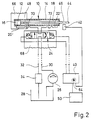
- a double-acting hydraulic cylinder is designated by 10 in total.
- a piston 12 is slidable, which together with a cylinder housing 14 two working spaces 16 and 18 limited.
- the latter are connected via working lines 20, 22 to a reversing valve, designated overall by 24.
- the working lines 20, 22 have a large length (in practice, for example, 70 m up to 100 m), as indicated by the broken lines in these lines.
- the reversing valve 24 is a 4/3 valve which is biased by springs into the middle rest position and is moved into one or the other of its working positions by energizing actuating magnets.
- the reversing valve 24 On the input side, the reversing valve 24 is connected to the delivery opening of a hydraulic pump 26, which draws in from a sump 28.
- the pressure line running between the hydraulic pump 26 and the reversing valve 24 is designated by 30 in FIG.
- a return line 32 which is also connected to the reversing valve 24, contains a cooler 34 for the hydraulic oil.
- a bypass line 36 which contains a normally closed bypass valve 18, is connected to the ends of the long working lines 20, 22 adjacent to the working cylinder.
- the latter is a solenoid valve and, like the reversing valve 24, is excited by a control unit 40.
- the control unit 40 receives as input signals the output signal of an end position sensor 42 which cooperates with end position marks 46, 48 carried by the piston rod 44 of the working cylinder 10.
- the control unit 40 receives further input signals from a keypad 50 connected to it and from the output D0 of a digital comparator 52.
- the comparator 52 receives a reference signal from a fixed value memory 54, which is continuously connected to the output signal of an analog / digital converter 56. Its input is connected to the outputs of two temperature sensors 60, 62, which is inserted into the working lines 20, 22 in the immediate vicinity of the working cylinder 10, via a schematically indicated switch 58, which is actuated synchronously with the reversing valve 24.
- the synchronization of the changeover switch 58 is selected such that that one of the temperature sensors 60, 62 is connected to the digital / analog converter which is acted upon by the hydraulic oil flowing out of the working cylinder 10.
- the changeover switch 58 can also be freely switched with a high frequency compared to the changeover frequency of the changeover valve 24, so that the digital / analog converter is acted upon rapidly in succession with analogue temperature signals for the outflowing or inflowing hydraulic oil.
- the control unit 40 is caused to interrupt the periodic reversal of the working cylinder 10 and the bypass valve 38 to the open position to control.
- the reversing valve 24 is brought into one of its working positions.
- the hydraulic pump 26 now presses cool hydraulic oil freshly sucked in from the sump 28 into the working lines 16 and 18 with low resistance and therefore the hot hydraulic oil displaced from the working lines 20, 22 passes back through the cooler 34 into the sump 28.
- control unit 40 closes the bypass valve 38 and the alternating one Excitation of the actuating magnets of the reversing valve 24 is resumed.
- the length of a rinsing cycle described in detail above is specified by a timer which forms part of the control unit 40.
- the rinsing time specified by this timer can e.g. can be set on a setting button 64 of the control unit 40 according to the respective length of the working lines 20, 22.
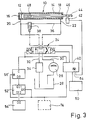
- the reversing valve 24 is arranged on a frame part 68 which is closely adjacent to a frame part 66 which carries the working cylinder 10, but is at least largely decoupled from it in terms of vibration.
- the frame part 68 is also decoupled in terms of vibration from other parts of the working device comprising the working cylinder 10.
- the connection of the reversing valve 24 to the working cylinder 10 now takes place via short working lines 20 ', 22', which have flexible sections 70, 72.
- the working lines 20 'and 22' now have a volume which is small compared to the volumes of the working spaces 16 and 18. Most of the hydraulic oil in the work rooms 16 and 18 is thus not swings with the work lines 20 'and 22' exchanged, but rather gets into the device circuit from the pressure line 30 to the return line 32. Thus, the hydraulic oil is also continuously through the cooler 34 circulated and sufficiently cooled.
- the working cycles of the working cylinder 10 can also be counted and the flushing of the working lines 20, 22 initiated after a predetermined number of working cycles .
- one of the output signals of the control unit 40 which is used to excite the reversing valve 24 can also be passed to the counter terminal C of a counter 56 ', the data output D0 of which is connected to the one data input DI 1 of a comparator 52', which returns its reference signal from a read-only memory 54 '.
- the counter 56 ' is reset as well as the triggering of a rinsing cycle by the output signal of the comparator 52'.
- the exemplary embodiment according to FIG. 3 otherwise works similarly to that according to FIG. 1.
- control terminal of the control unit 40 provided for initiating a flushing process can simply be connected to the output of a very low-frequency free-running clock generator 74, which then replaces the circuits 52'-54 'of FIG. 3, as indicated by the dashed lines there.
Landscapes
- Engineering & Computer Science (AREA)
- Chemical & Material Sciences (AREA)
- Analytical Chemistry (AREA)
- Physics & Mathematics (AREA)
- Fluid Mechanics (AREA)
- Mechanical Engineering (AREA)
- General Engineering & Computer Science (AREA)
- Fluid-Pressure Circuits (AREA)
- Placing Or Removing Of Piles Or Sheet Piles, Or Accessories Thereof (AREA)
Claims (7)
Priority Applications (1)
| Application Number | Priority Date | Filing Date | Title |
|---|---|---|---|
| AT88902481T ATE73907T1 (de) | 1987-03-27 | 1988-03-22 | Druckmittelbetriebene antriebseinrichtung. |
Applications Claiming Priority (2)
| Application Number | Priority Date | Filing Date | Title |
|---|---|---|---|
| DE3710028 | 1987-03-27 | ||
| DE19873710028 DE3710028A1 (de) | 1987-03-27 | 1987-03-27 | Druckmittelbetriebene antriebseinrichtung |
Publications (2)
| Publication Number | Publication Date |
|---|---|
| EP0362206A1 EP0362206A1 (fr) | 1990-04-11 |
| EP0362206B1 true EP0362206B1 (fr) | 1992-03-18 |
Family
ID=6324072
Family Applications (1)
| Application Number | Title | Priority Date | Filing Date |
|---|---|---|---|
| EP88902481A Expired - Lifetime EP0362206B1 (fr) | 1987-03-27 | 1988-03-22 | Transmission hydraulique |
Country Status (6)
| Country | Link |
|---|---|
| US (1) | US5072584A (fr) |
| EP (1) | EP0362206B1 (fr) |
| JP (1) | JPH02502842A (fr) |
| AT (1) | ATE73907T1 (fr) |
| DE (2) | DE3710028A1 (fr) |
| WO (1) | WO1988007633A1 (fr) |
Families Citing this family (17)
| Publication number | Priority date | Publication date | Assignee | Title |
|---|---|---|---|---|
| FR2666787B1 (fr) * | 1990-09-19 | 1992-12-18 | Aerospatiale | Actionneur hydraulique a mode hydrostatique de fonctionnement de preference en secours, et systeme de commande de vol le comportant. |
| US5456078A (en) * | 1994-08-12 | 1995-10-10 | Caterpillar Inc. | Method of purging a hydraulic system |
| GB2296046B (en) * | 1994-10-18 | 1998-07-15 | Automotive Products Plc | Actuation systems |
| DE19627974C2 (de) * | 1996-07-11 | 2003-02-06 | Getrag Getriebe Zahnrad | Hydraulische Stelleinheit und Verfahren zum Entlüften einer hydraulischen Stelleinheit |
| JPH11245831A (ja) * | 1998-03-05 | 1999-09-14 | Toyoda Mach Works Ltd | 油圧式動力舵取装置 |
| US6178871B1 (en) * | 1998-06-25 | 2001-01-30 | Tom Sutherland | Actuator and method of operating same |
| CA2290117C (fr) * | 1999-11-15 | 2005-05-10 | Wheeltronic Ltd. | Egalisateur de pression |
| JP2001180508A (ja) * | 1999-12-27 | 2001-07-03 | Toyota Autom Loom Works Ltd | パワーステアリングバルブ |
| ITMI20040197A1 (it) * | 2004-02-09 | 2004-05-09 | Astra Veicoli Ind S P A | Procedimento e circuito per la regolazione della portata di olio idraulico di raffreddamwento freni di un veicolo |
| US7421840B2 (en) * | 2004-03-08 | 2008-09-09 | Bosch Rexroth Corporation | Energy conversion and dissipation system |
| US7191593B1 (en) * | 2005-11-28 | 2007-03-20 | Northrop Grumman Corporation | Electro-hydraulic actuator system |
| SE531309C2 (sv) * | 2006-01-16 | 2009-02-17 | Volvo Constr Equip Ab | Styrsystem för en arbetsmaskin och förfarande för styrning av en hydraulcylinder hos en arbetsmaskin |
| JP4802852B2 (ja) * | 2006-05-16 | 2011-10-26 | コベルコ建機株式会社 | 作業機械の油圧回路 |
| US8042333B2 (en) * | 2007-03-14 | 2011-10-25 | Hampton Hydraulics | Oil cooling circuit for continuously reciprocating hydraulic cylinders |
| CN104204547A (zh) * | 2012-03-22 | 2014-12-10 | 优铁工有限公司 | 液压缸驱动回路用的冲洗回路 |
| JP7523259B2 (ja) * | 2020-06-19 | 2024-07-26 | 川崎重工業株式会社 | 液圧駆動システム |
| JP2025156819A (ja) * | 2024-04-02 | 2025-10-15 | キャタピラー エス エー アール エル | 建設機械の油圧回路 |
Family Cites Families (7)
| Publication number | Priority date | Publication date | Assignee | Title |
|---|---|---|---|---|
| US2688313A (en) * | 1950-03-21 | 1954-09-07 | Us Navy | Fluid pressure reciprocating motor and control valve apparatus |
| US2929212A (en) * | 1957-03-28 | 1960-03-22 | Gen Electric | Cooling means for fluid actuators |
| CH477630A (de) * | 1968-09-10 | 1969-08-31 | Hydrel Ag Maschf | Mindestens angenähert lastunabhängige Genauigkeitsumsteuerung an einem hydraulischen Leistungsantrieb für Wechselbewegungen eines Arbeitsorganes, beispielsweise bei Werkzeugmaschinen und Aufzügen |
| US3699847A (en) * | 1971-02-04 | 1972-10-24 | Mc Donnell Douglas Corp | Cooled hydraulic system |
| US4059042A (en) * | 1976-10-04 | 1977-11-22 | Caterpillar Tractor Co. | Hydraulic system for extremely cold environments |
| JPS57501440A (fr) * | 1980-09-29 | 1982-08-12 | ||
| US4779418A (en) * | 1987-02-17 | 1988-10-25 | M-B-W Inc. | Remote control system for a soil compactor |
-
1987
- 1987-03-27 DE DE19873710028 patent/DE3710028A1/de not_active Withdrawn
-
1988
- 1988-03-22 DE DE8888902481T patent/DE3869412D1/de not_active Expired - Lifetime
- 1988-03-22 JP JP63502563A patent/JPH02502842A/ja active Pending
- 1988-03-22 EP EP88902481A patent/EP0362206B1/fr not_active Expired - Lifetime
- 1988-03-22 US US07/399,488 patent/US5072584A/en not_active Expired - Fee Related
- 1988-03-22 WO PCT/EP1988/000231 patent/WO1988007633A1/fr not_active Ceased
- 1988-03-22 AT AT88902481T patent/ATE73907T1/de not_active IP Right Cessation
Also Published As
| Publication number | Publication date |
|---|---|
| JPH02502842A (ja) | 1990-09-06 |
| EP0362206A1 (fr) | 1990-04-11 |
| ATE73907T1 (de) | 1992-04-15 |
| DE3869412D1 (de) | 1992-04-23 |
| DE3710028A1 (de) | 1988-10-06 |
| WO1988007633A1 (fr) | 1988-10-06 |
| US5072584A (en) | 1991-12-17 |
Similar Documents
| Publication | Publication Date | Title |
|---|---|---|
| EP0362206B1 (fr) | Transmission hydraulique | |
| CH634129A5 (de) | Membranpumpe. | |
| EP2644903B1 (fr) | Procédé et dispositif de commande hydraulique pour la commande d'un consommateur | |
| DE102016124118A1 (de) | Hydraulischer Antrieb mit Eil- und Lasthub | |
| DE2355430A1 (de) | Vorrichtung zur steuerung wenigstens einer hydraulischen stell- bzw. antriebsvorrichtung | |
| WO2007140935A1 (fr) | Pompe à lubrifiant automatique avec piston d'entraînement à double action | |
| EP1105235B1 (fr) | Procede pour le reglage hydraulique des rouleaux des segments de guidage du brin d'une installation de coulee continue | |
| DE68903276T2 (de) | Vorrichtung zum spuelen von hydraulischen leitungen. | |
| DE1956835A1 (de) | Kraftuebertragungsvorrichtung | |
| DE1634915B2 (de) | Schaltung fuer hydraulikbagger | |
| EP0561185A1 (fr) | Commande hydraulique de tiroir pour vérins avec des vitesses de piston inégales | |
| DE102008013849A1 (de) | Steuergerät sowie dessen Verwendung | |
| DE10361619B4 (de) | Hydraulische Betätigungsvorrichtung | |
| DE10151810A1 (de) | Steuervorrichtung für fluidische Antriebe | |
| EP0238949A2 (fr) | Dispositif de transport d'un fluide d'une première région de pression à une seconde et retour | |
| DE487976C (de) | Hochdruck-Kolbenkompressoranlage | |
| DE2626971A1 (de) | Kolbenpumpe zur verwendung mit einer druckoel fuehrenden hydraulikanlage | |
| DE3420808A1 (de) | Antriebsanordnung mit zwei oder mehreren hydraulischen zylinder-kolbeneinheiten | |
| DE2821462A1 (de) | Automatische steuervorrichtung fuer hydraulikzylinder | |
| DE9210367U1 (de) | Hydraulisches Arbeitsaggregat | |
| DE7732705U1 (de) | Mit einem fliessenden und unter druck stehenden medium antreibbarer kolbenmotor | |
| DE3911278A1 (de) | Plunger-pumpe | |
| DE683599C (de) | Einrichtung zur Rueckfuehrung des Kraftschalters druckmittelbetriebener Regel- und Steuervorrichtungen | |
| AT202413B (de) | Elektrohydraulisches Stellgerät | |
| DE428293C (de) | Gegenzylinder bei Schuettelrutschen mit Hauptantriebsmotor |
Legal Events
| Date | Code | Title | Description |
|---|---|---|---|
| PUAI | Public reference made under article 153(3) epc to a published international application that has entered the european phase |
Free format text: ORIGINAL CODE: 0009012 |
|
| 17P | Request for examination filed |
Effective date: 19891110 |
|
| AK | Designated contracting states |
Kind code of ref document: A1 Designated state(s): AT BE CH DE FR GB IT LI NL SE |
|
| 17Q | First examination report despatched |
Effective date: 19910517 |
|
| GRAA | (expected) grant |
Free format text: ORIGINAL CODE: 0009210 |
|
| AK | Designated contracting states |
Kind code of ref document: B1 Designated state(s): AT BE CH DE FR GB IT LI NL SE |
|
| PG25 | Lapsed in a contracting state [announced via postgrant information from national office to epo] |
Ref country code: IT Free format text: LAPSE BECAUSE OF FAILURE TO SUBMIT A TRANSLATION OF THE DESCRIPTION OR TO PAY THE FEE WITHIN THE PRE;WARNING: LAPSES OF ITALIAN PATENTS WITH EFFECTIVE DATE BEFORE 2007 MAY HAVE OCCURRED AT ANY TIME BEFORE 2007. THE CORRECT EFFECTIVE DATE MAY BE DIFFERENT FROM THE ONE RECORDED.SCRIBED TIME-LIMIT Effective date: 19920318 Ref country code: SE Effective date: 19920318 Ref country code: BE Effective date: 19920318 |
|
| REF | Corresponds to: |
Ref document number: 73907 Country of ref document: AT Date of ref document: 19920415 Kind code of ref document: T |
|
| PG25 | Lapsed in a contracting state [announced via postgrant information from national office to epo] |
Ref country code: AT Effective date: 19920322 |
|
| PG25 | Lapsed in a contracting state [announced via postgrant information from national office to epo] |
Ref country code: CH Effective date: 19920331 Ref country code: LI Effective date: 19920331 |
|
| REF | Corresponds to: |
Ref document number: 3869412 Country of ref document: DE Date of ref document: 19920423 |
|
| ET | Fr: translation filed | ||
| GBT | Gb: translation of ep patent filed (gb section 77(6)(a)/1977) | ||
| REG | Reference to a national code |
Ref country code: CH Ref legal event code: PL |
|
| PLBE | No opposition filed within time limit |
Free format text: ORIGINAL CODE: 0009261 |
|
| STAA | Information on the status of an ep patent application or granted ep patent |
Free format text: STATUS: NO OPPOSITION FILED WITHIN TIME LIMIT |
|
| PGFP | Annual fee paid to national office [announced via postgrant information from national office to epo] |
Ref country code: FR Payment date: 19930208 Year of fee payment: 6 |
|
| PGFP | Annual fee paid to national office [announced via postgrant information from national office to epo] |
Ref country code: GB Payment date: 19930305 Year of fee payment: 6 |
|
| 26N | No opposition filed | ||
| PGFP | Annual fee paid to national office [announced via postgrant information from national office to epo] |
Ref country code: DE Payment date: 19930519 Year of fee payment: 6 |
|
| PG25 | Lapsed in a contracting state [announced via postgrant information from national office to epo] |
Ref country code: GB Effective date: 19940322 |
|
| PGFP | Annual fee paid to national office [announced via postgrant information from national office to epo] |
Ref country code: NL Payment date: 19940331 Year of fee payment: 7 |
|
| GBPC | Gb: european patent ceased through non-payment of renewal fee |
Effective date: 19940322 |
|
| PG25 | Lapsed in a contracting state [announced via postgrant information from national office to epo] |
Ref country code: FR Effective date: 19941130 |
|
| PG25 | Lapsed in a contracting state [announced via postgrant information from national office to epo] |
Ref country code: DE Effective date: 19941201 |
|
| REG | Reference to a national code |
Ref country code: FR Ref legal event code: ST |
|
| PG25 | Lapsed in a contracting state [announced via postgrant information from national office to epo] |
Ref country code: NL Effective date: 19951001 |
|
| NLV4 | Nl: lapsed or anulled due to non-payment of the annual fee |
Effective date: 19951001 |