EP0362252B1 - Antenne pour vehicules - Google Patents
Antenne pour vehicules Download PDFInfo
- Publication number
- EP0362252B1 EP0362252B1 EP88904579A EP88904579A EP0362252B1 EP 0362252 B1 EP0362252 B1 EP 0362252B1 EP 88904579 A EP88904579 A EP 88904579A EP 88904579 A EP88904579 A EP 88904579A EP 0362252 B1 EP0362252 B1 EP 0362252B1
- Authority
- EP
- European Patent Office
- Prior art keywords
- conductor
- antenna
- strip
- window
- vehicle
- Prior art date
- Legal status (The legal status is an assumption and is not a legal conclusion. Google has not performed a legal analysis and makes no representation as to the accuracy of the status listed.)
- Expired - Lifetime
Links
- 239000004020 conductor Substances 0.000 claims abstract description 39
- 230000002093 peripheral effect Effects 0.000 claims description 9
- 230000001413 cellular effect Effects 0.000 abstract description 6
- 230000000694 effects Effects 0.000 description 4
- 230000005540 biological transmission Effects 0.000 description 3
- 238000010586 diagram Methods 0.000 description 3
- 239000011521 glass Substances 0.000 description 3
- 230000005404 monopole Effects 0.000 description 3
- 239000004033 plastic Substances 0.000 description 3
- 229920003023 plastic Polymers 0.000 description 3
- 239000000853 adhesive Substances 0.000 description 2
- 230000001070 adhesive effect Effects 0.000 description 2
- 239000000463 material Substances 0.000 description 2
- 230000001464 adherent effect Effects 0.000 description 1
- 239000005357 flat glass Substances 0.000 description 1
- 239000002184 metal Substances 0.000 description 1
- 238000007789 sealing Methods 0.000 description 1
Images


Classifications
-
- H—ELECTRICITY
- H01—ELECTRIC ELEMENTS
- H01Q—ANTENNAS, i.e. RADIO AERIALS
- H01Q1/00—Details of, or arrangements associated with, antennas
- H01Q1/12—Supports; Mounting means
- H01Q1/1271—Supports; Mounting means for mounting on windscreens
Definitions
- This invention relates to an antenna for use on a motor vehicle, particularly for cellular radio.
- such antennas do not project outside the vehicle and are not therefore susceptible to inadvertent damage or vandalisation. Also, mounting holes in the vehicle bodywork can be avoided. Efficient reception can be achieved with such antennas on the usual AM and FM broadcast bands, and efficient transmission can be achieved in the 4m to 2m VHF mobile radio band, if necessary with the aid of matching and tuning circuitry.
- a conductor applied to a window can be used as an antenna and examples of such antennas are shown in FR-A-2571179 and JP-A-59196605.
- the problem with the types of antennas disclosed in these documents are that in order to obtain adequate reception of signals the conductors need to be relatively large in size and therefore can obscure a driver's vision.
- these antennas are inductively linked to a part of the vehicle body and thus do not operate in a manner equivalent to the conventional short whip antenna mentioned above.
- An object of the present invention is to provide an antenna which is suitable for use with cellular radio yet which is incorporated in a vehicle window.
- a vehicle window having a plurality of peripheral edges comprising a top edge, a bottom edge and two upright side edges, and an antenna for use with radio apparatus, said antenna comprising in combination an elongate conductor, applied to one surface of said window, and a separate conductive strip also applied to said surface of the said window and defining a ground plane for the said antenna, characterised in that said conductive strip extends along, in close proximity to, one of said peripheral edges so as to be capacitatively linked thereto to provide said ground plane, the length of the said conductive strip extending along said one of said peripheral edges to provide the said ground plane being greater than half the wavelength of the central frequency of the frequency band to which said radio apparatus is tuned, said elongate conductor having terminal means at one end thereof, said one end being located adjacent to the said strip and separated from said strip by a narrow gap, and the other end of the said elongate conductor projecting freely away from said strip, the length of said elongate conductor being a minor proportion of the
- the conductor may be fixed to a vehicle rear window near the top edge thereof. Where the window also has heater wires these should be separate from the antenna.
- the conductor preferably extends in a direction from a top edge towards a bottom edge of the window and thus, the conductor may extend in a vertical plane.
- the window is a rear window of a motor car, although it is to be understood that the invention can be applied to any suitable window of any suitable vehicle.
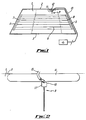
- the window comprises a glass pane 1 which is generally rectangular or trapezoidal and has top and bottom long edges 2, 3 which extend at least substantially horizontally, and two short upright side edges 4, 5.
- the pane 1 may be flat or curved and lies in a plane (or is curved relative to a plane) which is substantially vertical or inclined to the vertical, as is conventional.
- the pane 1 fits within an opening in a metal body of the vehicle and is sealed relative to the periphery of the opening with a sealing gasket formed from rubber or similar material.
- the pane 1 incorporates a heater (demister) which comprises a series of parallel, horizontal wires 6 running between upright busbars 7, 8, such wires and bars being incorporated in the inner surface of the glass pane or applied thereto e.g. as narrow, flat, printed, conductive strips.
- the bus bars 7, 8 are connected to the usual d.c. power supply of the motor car via an operating switch.
- one busbar 7 is connected to earths (i.e. the car body), and the other busbar 8 is connected by a lead to positive power supply via the operating switch which may be located for example on the car dashboard.
- the heater wires 6 extend across a major part of the surface area of the window pane but there is a space between the top edge 2 of the window pane 1 and the uppermost heater wire 6. In this space there is a short, straight upright conductor 9 which is incorporated in or applied to the inner surface of the pane.
- the conductor 9 may comprise a 0.4mm wire fixed by adhesive to the surface of the pane 1, or the conductor may comprise a narrow flat printed conductive strip, say 1 to 11 ⁇ 2 mm wide.
- the conductor 9 lies in a vertical plane and terminates at its upper end 10 close to the top edge 2 of the window pane 1 near to but well spaced from one side edge 5.
- the top end 10 of the conductor 9 has thereat a portion of increased width which forms a square terminal 11, say 31 ⁇ 2 to 4 mm square.
- This strip 12 may be a flat printed conductive strip (say 10-20 mm wide) of similar nature to the printed strips conventionally used for window heaters (demisters).
- a very narrow gap (say 1-2 mm) is defined between the terminal 11 and the strip 12 and the terminal 11 is located in the middle of the strip 12.
- a coaxial cable 13 has its central conductor connected to the terminal 11 and its outer conductor connected to the middle of the strip 12 immediately above the terminal 11.
- the cable 13 is led around the interior of the car to a conventional cellular radio/transmitter 14 which may be mounted e.g. on the car dashboard.
- the cable 13 is connected directly to the usual antenna socket of the radio/ transmitter.
- the radio/transmitter is tuned to operate in the usual cellular radio band i.e. 890-960MHz.
- the conductor 9 acts as an antenna for the radio/transmitter 14 and the strip 12 acts to define a ground plane for the antenna.
- the strip 12 extends up to the edge 2 of the window pane 1 and in effect forms part of the vehicle body in so far as the strip is so close to the body as to be capacitively linked thereto.
- the width of the strip 12 is large enough to ensure that the strip projects beyond any peripheral window trim thereby to avoid spurious capacitive effects with the trim.
- the length of the strip 12 is not critical but is greater than half the wavelength of the central frequency of the band to which the radio/transmitter is tuned.
- the conductor 9 is relatively short, that is, the length of the conductor 9 is much less than the length of any of the edges 2, 3, 4, 5 of the window pane 1. Moreover the length of the conductor 9 is less than the quarter-wavelength of the middle frequency of the band to which the radio apparatus is tuned. More specifically the effective length of the conductor 9, i.e. the length from the bottom end of the conductor to the bottom edge of the ground plane strip 12 is trimmed to give resonance at the mid-band frequency of 925MHz of the band to which the radio apparatus is tuned. In practice, the length will be approximately 55mm which is approximately 30% less than the free-space quarter-wavelength, this being possible due to the dielectric effect of the glass which modifies the antenna properties of the conductor 9.
- the coaxial lead is connected directly to the radio apparatus and matching circuitry or the like is not required since the antenna structure provides 'ideal' matching to the radio apparatus.
- a bandwidth of the order of 100MHz (1.3:1 vswr) is attainable.
- the conductor 9 may be applied to a small transparent sheet of soft plastics (e.g. by printing on the plastics), such sheet being affixed to the window pane 1 by adhesive or by virtue of the adherent properties of the plastics material.
- the antenna is shown applied to a rear window it is to be understood that it may be applied to a side or front window. Being so small, the antenna does not significantly obscure vision.
- Figure 3 shows typical performance of a conventional roof-mounted rod antenna (effectively quarter-wave monopole), and Figure 4 shows typical performance of the antenna of Figures 1 and 2.
- Figures 3 and 4 are polar diagrams recorded by driving a car (Ford Granada) fitted with the antennas in a tight circle at a distance in the range 200-500m from a low power 925 MHz test transmitter.
- Figure 3 shows the power of the received signal with the roof-mounted monopole
- Figure 4 shows the power of the received signal with the antenna of Figures 1 and 2 applied to the rear window.
- the polar diagrams show that the performance obtained with the antenna of Figures 1 and 2 is surprisingly roughly comparable with that of a conventional antenna.
Landscapes
- Details Of Aerials (AREA)
- Fittings On The Vehicle Exterior For Carrying Loads, And Devices For Holding Or Mounting Articles (AREA)
Abstract
Claims (8)
- Fenêtre de véhicule ayant une pluralité de bords périphériques comprenant un bord supérieur (2), un bord inférieur (3) et deux bords latéraux droits (4, 5), et une antenne pour une utilisation avec un appareil de radio, ladite antenne comprenant en combinaison un conducteur allongé (9), appliqué sur une surface de ladite fenêtre, et une bande (12) conductrice séparée appliquée également sur ladite surface de ladite fenêtre et définissant un plan de masse pour ladite antenne, caractérisée en ce que ladite bande conductrice (12) s'étend le long et à la proximité immédiate d'un (2) desdits bords périphériques de manière à être reliée à celui-ci de manière capacitive pour fournir ledit plan de masse, la longueur de ladite bande conductrice s'étendant le long dudit bord périphérique pour fournir ledit plan de masse étant supérieure à la moitié de la longueur d'onde de la fréquence centrale de la bande de fréquence à laquelle l'appareil de radio est accordé, ledit conducteur allongé (9) ayant des moyens de borne à une extrémité de celui-ci, ladite extrémité étant adjacente à ladite bande (12) et séparée de ladite bande par un espace étroit, et l'autre extrémité dudit conducteur allongé s'écartant librement de ladite bande, la longueur dudit conducteur allongé (9) étant un rapport mineur de la longueur de chacun desdlts bords périphériques (2, 3, 4, 5).
- Fenêtre de véhicule selon la revendication 1, dans laquelle le conducteur (9) s'étend dans une direction depuis un bord supérieur (2) vers un bord inférieur (3) de la fenêtre.
- Fenêtre de véhicule selon la revendication 2, dans laquelle le conducteur (9) s'étend dans un plan vertical.
- Fenêtre de véhicule selon l'une quelconque des revendications 1 à 3, dans laquelle ladite antenne est utilisée avec ledit appareil de radio fonctionnant dans la bande de fréquence de 890 à 960 MHz, et la longueur du conducteur (9) est inférieure au quart de la longueur d'onde en espace libre de la fréquence de milieu de bande.
- Fenêtre de véhicule selon les revendications 3 et 4, dans laquelle l'extrémité (11) du conducteur (9) éloignée de ladite bande est espacée de la bande par une distance inférieure au quart de la longueur d'onde en espace libre de la fréquence de milieu de bande.
- Fenêtre de véhicule selon la revendication 5, dans laquelle ladite distance est d'au moins 30 % inférieure au quart de la longueur d'onde en espace libre de la fréquence de milieu de bande.
- Véhicule ayant une fenêtre avec une antenne selon l'une quelconque des revendications précédentes.
- Véhicule selon la revendication 7, dans lequel ledit appareil de radio comprend des éléments de circuit de transmission pour transmettre des signaux radio dans la bande de fréquence prédéterminée via ladite antenne.
Applications Claiming Priority (3)
| Application Number | Priority Date | Filing Date | Title |
|---|---|---|---|
| GB878711995A GB8711995D0 (en) | 1987-05-21 | 1987-05-21 | Vehicle antenna |
| GB8711995 | 1987-05-21 | ||
| PCT/GB1988/000409 WO1988009569A1 (fr) | 1987-05-21 | 1988-05-23 | Antenne pour vehicules |
Publications (2)
| Publication Number | Publication Date |
|---|---|
| EP0362252A1 EP0362252A1 (fr) | 1990-04-11 |
| EP0362252B1 true EP0362252B1 (fr) | 1995-08-09 |
Family
ID=10617682
Family Applications (1)
| Application Number | Title | Priority Date | Filing Date |
|---|---|---|---|
| EP88904579A Expired - Lifetime EP0362252B1 (fr) | 1987-05-21 | 1988-05-23 | Antenne pour vehicules |
Country Status (5)
| Country | Link |
|---|---|
| EP (1) | EP0362252B1 (fr) |
| JP (1) | JPH02504453A (fr) |
| DE (1) | DE3854298T2 (fr) |
| GB (2) | GB8711995D0 (fr) |
| WO (1) | WO1988009569A1 (fr) |
Families Citing this family (11)
| Publication number | Priority date | Publication date | Assignee | Title |
|---|---|---|---|---|
| JPH0623054Y2 (ja) * | 1987-10-07 | 1994-06-15 | 日本板硝子株式会社 | 自動車用アンテナ装置 |
| US5264858A (en) * | 1990-07-31 | 1993-11-23 | Asahi Glass Company Ltd. | Glass antenna for a telephone of an automobile |
| FI89754C (fi) * | 1990-08-01 | 1993-11-10 | Window Antenna Oy | Antenn |
| JPH05226919A (ja) * | 1991-06-26 | 1993-09-03 | Libbery Owens Ford Co | 窓組込み型車輌用アンテナ |
| JP2538140B2 (ja) * | 1991-06-28 | 1996-09-25 | セントラル硝子株式会社 | 車両用ガラスアンテナ |
| JP2593899Y2 (ja) * | 1992-02-05 | 1999-04-19 | 日本板硝子株式会社 | 自動車用窓ガラスアンテナ装置 |
| JPH05283921A (ja) * | 1992-03-31 | 1993-10-29 | Pioneer Electron Corp | 車載用アンテナ |
| DE4237818C3 (de) * | 1992-11-10 | 2000-12-14 | Sekurit Saint Gobain Deutsch | Scheibenantenne für Kraftfahrzeuge |
| US6008766A (en) * | 1992-11-27 | 1999-12-28 | Nippon Sheet Glass Co., Ltd. | Rear window glass antenna for automobiles |
| DE4410542B4 (de) * | 1994-03-26 | 2004-07-22 | Fuba Automotive Gmbh & Co. Kg | Anordnung für den Betrieb von Funkgeräten |
| DE19612958A1 (de) * | 1996-04-01 | 1997-10-02 | Fuba Automotive Gmbh | Antennenverstärker auf einer Fensterscheibe |
Family Cites Families (5)
| Publication number | Priority date | Publication date | Assignee | Title |
|---|---|---|---|---|
| US4233337A (en) * | 1978-05-01 | 1980-11-11 | International Business Machines Corporation | Method for forming semiconductor contacts |
| JPS54152447A (en) * | 1978-05-22 | 1979-11-30 | Nippon Sheet Glass Co Ltd | Very high frequency receiving antenna |
| JPS5817705A (ja) * | 1981-07-23 | 1983-02-02 | Mazda Motor Corp | 自動車の窓ガラス加熱用導電線を兼ねたアンテナ |
| JPH0767043B2 (ja) * | 1983-04-22 | 1995-07-19 | 住友電気工業株式会社 | ユニポール型車載tvアンテナ |
| JPS6182502A (ja) * | 1984-09-29 | 1986-04-26 | Pioneer Electronic Corp | 車輌用アンテナ装置 |
-
1987
- 1987-05-21 GB GB878711995A patent/GB8711995D0/en active Pending
-
1988
- 1988-05-23 JP JP63504324A patent/JPH02504453A/ja active Pending
- 1988-05-23 DE DE3854298T patent/DE3854298T2/de not_active Expired - Fee Related
- 1988-05-23 WO PCT/GB1988/000409 patent/WO1988009569A1/fr not_active Ceased
- 1988-05-23 EP EP88904579A patent/EP0362252B1/fr not_active Expired - Lifetime
-
1989
- 1989-11-17 GB GB8927510A patent/GB2229581B/en not_active Expired
Also Published As
| Publication number | Publication date |
|---|---|
| DE3854298T2 (de) | 1996-04-18 |
| GB8711995D0 (en) | 1987-06-24 |
| WO1988009569A1 (fr) | 1988-12-01 |
| GB8927510D0 (en) | 1990-02-21 |
| EP0362252A1 (fr) | 1990-04-11 |
| DE3854298D1 (de) | 1995-09-14 |
| GB2229581B (en) | 1991-05-01 |
| GB2229581A (en) | 1990-09-26 |
| JPH02504453A (ja) | 1990-12-13 |
Similar Documents
| Publication | Publication Date | Title |
|---|---|---|
| JP3568011B2 (ja) | 車体の少くとも1個所の窓ガラス用開口にアンテナ窓ガラスが装着されている自動車 | |
| US6118410A (en) | Automobile roof antenna shelf | |
| US10811760B2 (en) | Multi-band window antenna | |
| US8576130B2 (en) | Wideband antenna | |
| US3599214A (en) | Automobile windshield antenna | |
| US6211831B1 (en) | Capacitive grounding system for VHF and UHF antennas | |
| CN101682108B (zh) | 汽车用高频玻璃天线 | |
| US5629712A (en) | Vehicular slot antenna concealed in exterior trim accessory | |
| US5293174A (en) | Vehicle antenna | |
| KR0145052B1 (ko) | 차량용 안테나 및 그 설정방법 | |
| KR20120080648A (ko) | 자동차용 유리 안테나 | |
| WO1988009569A1 (fr) | Antenne pour vehicules | |
| US7242357B2 (en) | Antenna for vehicle | |
| US4749998A (en) | Antenna device for an automobile | |
| US3793590A (en) | Window mounted vehicular radio antenna | |
| JP2824789B2 (ja) | 広帯域ループアンテナ | |
| US4090202A (en) | Multiband antenna for automobile windshield | |
| CN101345335A (zh) | 汽车用高频天线 | |
| CN106654509B (zh) | 车辆用玻璃天线和具备该车辆用玻璃天线的后部窗玻璃 | |
| JP2005229140A (ja) | 車両用アンテナ | |
| JP2003101318A (ja) | 自動車用窓ガラスアンテナ | |
| JP3556830B2 (ja) | 自動車用のガラスアンテナ | |
| JP2002204112A (ja) | 車両用アンテナ装置 | |
| JPS63292702A (ja) | 除曇ヒ−タ線付き自動車用窓ガラス | |
| JP2005354176A (ja) | 車載用アンテナ |
Legal Events
| Date | Code | Title | Description |
|---|---|---|---|
| PUAI | Public reference made under article 153(3) epc to a published international application that has entered the european phase |
Free format text: ORIGINAL CODE: 0009012 |
|
| 17P | Request for examination filed |
Effective date: 19891121 |
|
| AK | Designated contracting states |
Kind code of ref document: A1 Designated state(s): DE FR GB IT SE |
|
| RAP1 | Party data changed (applicant data changed or rights of an application transferred) |
Owner name: BSH INDUSTRIES LIMITED |
|
| 17Q | First examination report despatched |
Effective date: 19920609 |
|
| GRAA | (expected) grant |
Free format text: ORIGINAL CODE: 0009210 |
|
| AK | Designated contracting states |
Kind code of ref document: B1 Designated state(s): DE FR GB IT SE |
|
| REF | Corresponds to: |
Ref document number: 3854298 Country of ref document: DE Date of ref document: 19950914 |
|
| ITF | It: translation for a ep patent filed | ||
| ET | Fr: translation filed | ||
| PG25 | Lapsed in a contracting state [announced via postgrant information from national office to epo] |
Ref country code: GB Effective date: 19960523 |
|
| PLBE | No opposition filed within time limit |
Free format text: ORIGINAL CODE: 0009261 |
|
| STAA | Information on the status of an ep patent application or granted ep patent |
Free format text: STATUS: NO OPPOSITION FILED WITHIN TIME LIMIT |
|
| 26N | No opposition filed | ||
| GBPC | Gb: european patent ceased through non-payment of renewal fee |
Effective date: 19960523 |
|
| PGFP | Annual fee paid to national office [announced via postgrant information from national office to epo] |
Ref country code: SE Payment date: 19980518 Year of fee payment: 11 |
|
| PG25 | Lapsed in a contracting state [announced via postgrant information from national office to epo] |
Ref country code: SE Free format text: LAPSE BECAUSE OF NON-PAYMENT OF DUE FEES Effective date: 19990524 |
|
| PGFP | Annual fee paid to national office [announced via postgrant information from national office to epo] |
Ref country code: FR Payment date: 19990527 Year of fee payment: 12 |
|
| PGFP | Annual fee paid to national office [announced via postgrant information from national office to epo] |
Ref country code: DE Payment date: 19990728 Year of fee payment: 12 |
|
| EUG | Se: european patent has lapsed |
Ref document number: 88904579.5 |
|
| PG25 | Lapsed in a contracting state [announced via postgrant information from national office to epo] |
Ref country code: FR Free format text: LAPSE BECAUSE OF NON-PAYMENT OF DUE FEES Effective date: 20010131 |
|
| PG25 | Lapsed in a contracting state [announced via postgrant information from national office to epo] |
Ref country code: DE Free format text: LAPSE BECAUSE OF NON-PAYMENT OF DUE FEES Effective date: 20010301 |
|
| REG | Reference to a national code |
Ref country code: FR Ref legal event code: ST |
|
| PG25 | Lapsed in a contracting state [announced via postgrant information from national office to epo] |
Ref country code: IT Free format text: LAPSE BECAUSE OF NON-PAYMENT OF DUE FEES;WARNING: LAPSES OF ITALIAN PATENTS WITH EFFECTIVE DATE BEFORE 2007 MAY HAVE OCCURRED AT ANY TIME BEFORE 2007. THE CORRECT EFFECTIVE DATE MAY BE DIFFERENT FROM THE ONE RECORDED. Effective date: 20050523 |