EP0362256B1 - Lichtdetektor für ein bilderzeugungsgerät mittels einer transparenten lichtstimulierbaren phosphorschicht - Google Patents
Lichtdetektor für ein bilderzeugungsgerät mittels einer transparenten lichtstimulierbaren phosphorschicht Download PDFInfo
- Publication number
- EP0362256B1 EP0362256B1 EP88904818A EP88904818A EP0362256B1 EP 0362256 B1 EP0362256 B1 EP 0362256B1 EP 88904818 A EP88904818 A EP 88904818A EP 88904818 A EP88904818 A EP 88904818A EP 0362256 B1 EP0362256 B1 EP 0362256B1
- Authority
- EP
- European Patent Office
- Prior art keywords
- light
- phosphor sheet
- face
- light detector
- light guide
- Prior art date
- Legal status (The legal status is an assumption and is not a legal conclusion. Google has not performed a legal analysis and makes no representation as to the accuracy of the status listed.)
- Expired - Lifetime
Links
Images



Classifications
-
- G—PHYSICS
- G01—MEASURING; TESTING
- G01T—MEASUREMENT OF NUCLEAR OR X-RADIATION
- G01T1/00—Measuring X-radiation, gamma radiation, corpuscular radiation, or cosmic radiation
- G01T1/16—Measuring radiation intensity
- G01T1/20—Measuring radiation intensity with scintillation detectors
- G01T1/2012—Measuring radiation intensity with scintillation detectors using stimulable phosphors, e.g. stimulable phosphor sheets
- G01T1/2014—Reading out of stimulable sheets, e.g. latent image
-
- G—PHYSICS
- G03—PHOTOGRAPHY; CINEMATOGRAPHY; ANALOGOUS TECHNIQUES USING WAVES OTHER THAN OPTICAL WAVES; ELECTROGRAPHY; HOLOGRAPHY
- G03B—APPARATUS OR ARRANGEMENTS FOR TAKING PHOTOGRAPHS OR FOR PROJECTING OR VIEWING THEM; APPARATUS OR ARRANGEMENTS EMPLOYING ANALOGOUS TECHNIQUES USING WAVES OTHER THAN OPTICAL WAVES; ACCESSORIES THEREFOR
- G03B42/00—Obtaining records using waves other than optical waves; Visualisation of such records by using optical means
- G03B42/02—Obtaining records using waves other than optical waves; Visualisation of such records by using optical means using X-rays
Definitions
- the invention relates to apparatus for reading out the image stored in a photostimulable phosphor image recording medium, and more particularly to apparatus for detecting the radiation emitted from a transparent photostimulable phosphor sheet in response to interrogation by stimulating radiation.
- a photostimulable phosphor sheet is exposed to an imagewise pattern of high energy short wavelength radiation, such as x-radiation, to record a latent image pattern in the photostimulable phosphor sheet.
- the latent image is read out by stimulating the phosphor with a relatively long wavelength stimulating radiation, such as red or infrared light.
- a relatively long wavelength stimulating radiation such as red or infrared light.
- the photostimulable phosphor releases emitted radiation of an intermediate wavelength, such as blue or violet light, in proportion to the quantity of short wavelength radiation that was received.
- the photostimulable phosphor sheet is scanned in a raster pattern by a beam of light produced for example by a laser deflected by an oscillating or rotating scanning mirror, and the emitted radiation is sensed by a photodetector such as a photomultiplier tube, to produce the electronic image signal.
- a photodetector such as a photomultiplier tube
- the photostimulable phosphor sheet is turbid to both stimulating and emitted wavelengths of light.
- the minimum pixel size, and hence the resolution that can be achieved corresponds to the scattered area of the scanning beam within the stimulable phosphor sheet itself. It has been proposed that the resolution of a photostimulable phosphor imaging system may be greatly improved by making the photostimulable phosphor sheet transparent, thereby enabling a reduction in the effective pixel size, since the apparent size of the beam is not increased by scattering.
- the transparent photostimulable phosphor sheet has a drawback, in that a large fraction of the emitted light is totally internally reflected within the phosphor sheet and is not collected by conventional light detectors.
- the only emitted light that escapes from the surface of the photostimulable phosphor sheet is that which is emitted in the solid angle subtended by the light rays incident at less than a critical angle to the surface.
- index of refraction 1.6
- One solution to this problem is to employ a photostimulable phosphor sheet that comprises a photostimulable phosphor dispersed in a polymeric binder.
- the polymeric binder is selected such that its index of refraction matches that of the phosphor at the stimulating wavelength, but does not match that of the phosphor at the emitted wavelength.
- the emitted wavelength is scattered and is not trapped by total internal reflection, while the benefits of the transparent phosphor sheet are achieved for the stimulating wavelength. See Canadian Patent No. 1,175,647 issued October 9, 1984 to DeBoer & Luckey.
- JP-A-60-12539 shows stimulable phosphor imaging apparatus where a sensor is coupled to a light collector by a layer of index matching liquid.
- U.S. Patent 4,578,581 issued March 25, 1986 to Tanaka et al. shows a stimulable phosphor imaging apparatus employing a photostimulable phosphor sheet and including a light sensor for sensing light emitted by the stimulable phosphor sheet and generating an electrical signal in response thereto.
- a light detector comprising a light sensing means having a light receiving face, and means for making optical contact with one surface of the transparent phosphor sheet, and with the light receiving face of the light sensing means, to optically couple the light sensing means to the surface of the phosphor sheet, thereby preventing total internal reflection in the areas of optical contact.
- the optical coupling means comprises a light guide having an input face in optical contact with the surface of the transparent phosphor sheet, and an output face in optical contact with the light receiving face of the light sensing means.
- the light receiving face is a rectangular area having a long axis parallel to the direction of a scanning beam of stimulating radiation.
- Transport means are provided for relative movement between the phosphor sheet and the light detector in a direction perpendicular to the long axis of the light receiving face.
- Optical contact between the light receiving face and the phosphor sheet is provided by means for maintaining a layer of index matching fluid between the surface of the phosphor sheet and the input face of the light guide.
- Fig. 2 illustrates the effect of a scanning beam S on a transparent photostimulable phosphor sheet 10 having an index of refraction n p greater than 1.
- the scanning beam S stimulates the emission of light in all directions within the phosphor sheet. Only the emitted light rays within a solid angle subtended by angle ⁇ c (illustrated by solid lines in Fig. 2) can escape from the surface of the transparent phosphor sheet 10. The rest of the rays (represented by phantom lines in Fig. 2) are trapped within the phosphor sheet by total internal reflection.
- ⁇ escape efficiency
- the total light energy from both the top and the bottom of the sheet is proportional to 2 ⁇ .
- n p of 1.6 the escape efficiency is approximately 22%. Therefore, the fraction of light available for collection in a conventional light collector is 11% for collection from one side of the sheet, or 22% from both sides.
- a mirror can be placed on one side of the sheet and light collected from the other side of the sheet. In this case, the escape efficiency ⁇ is: where R is the reflectance of the mirror.
- a photosensor is optically coupled to the surface of the transparent phosphor. From equation (1), it is seen that by changing the index of refraction of the medium immediately adjacent the stimulable phosphor sheet to a material having an index more nearly matching that of the stimulable phosphor sheet, the critical angle ⁇ c can be made to approach 90°.
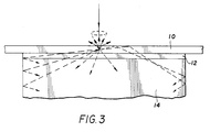
- Fig. 3 is a schematic diagram showing how the use of a layer of index matching material 12 that is in optical contact with the transparent phosphor sheet 10 and a light detector 14, increases the amount of light that arrives at the input face of the light detector.
- Fig. 1 is a schematic diagram illustrating apparatus according to the present invention.
- a photostimulable phosphor sheet 10 is scanned by a beam of stimulating radiation S from a laser 16.
- the beam S is deflected in a fast or line scan direction as shown by arrow A by rotating polygon mirror 18.
- Laser scanners being well known in the art, focusing and field flattening optics present in the actual apparatus are not shown in the schematic diagram.
- the stimulable sheet is advanced in a slow or page scan direction as shown by arrow B by a sheet drive mechanism including a motor 20 and a drive roller 22.
- Light emitted from the stimulable phosphor sheet 10 is collected and detected by light detector 14 that is optically coupled to the bottom surface of the sheet by a layer of index matching material 12.
- the phosphor sheet 10 may be self-supporting, or may include a transparent substrate for support, such as glass (not shown).
- the light detector 14 senses the light emitted from the phosphor sheet 10 and produces an output signal O.
- a preferred mode of maintaining a layer of index matching liquid between the light detector 14 and the phosphor sheet 10 will be described.
- Fig. 4 is an end view of the light detector 14 which includes a transparent light guide 24 for conducting light emitted from stimulable phosphor sheet 10 to the input face of a sensing means such as a photomultiplier tube 26.
- the light guide 24 comprises a block of transparent material having reflective side walls 23 achieved, for example by a dielectric or metalized coating on the sides of the transparent block.
- the bottom face 28 of the transparent light guide 24 is in optical contact with a band pass optical filter 30.
- the filter 30 is in turn, in optical contact with the light receiving face of the photomultiplier tube 26.
- the bandpass optical filter 30 passes light of the emitted wavelength and absorbs light of the stimulating wavelength to keep the stimulating light from being detected by the photomultiplier 26.
- the transparent light guide 24 is held in a frame 32 which defines a passage 34 for introducing a layer 12 of index matching liquid between the upper face 36 of the transparent light guide 24 and the bottom surface of the phosphor sheet 10.
- the frame 32 also defines a trough 38 surrounding the top of the light guide 24 for catching the index matching liquid and returning it to a sump 40.
- a pump 42 recirculates the liquid to the passage 34. In operation, the pump 42 continuously recirculates the index matching liquid in a laminar flow between the upper surface 36 of the light guide and the phosphor sheet 10, while the phosphor sheet is transported past the light detector 14.
- Fig. 5 is a top perspective view of the light detector 14. As can be seen in Fig. 5, the opening from passage 34 is a slot 44 that runs parallel to the edge of the light guide surface 36.
- a vacuum skive 441 (shown in phantom) is provided to remove any excess index matching liquid that is carried past the light detector 14 on the underside of the phosphor sheet 10.
- the index matching liquid removed from the underside of the sheet is conducted through a vacuum pump 46 back into sump 40.
- Fig. 6 is a side view of the light detector 14 of Fig. 4, showing a dichroic filter 48 for passing the beam S of stimulating radiation and reflecting any emitted radiation that escapes internal reflection in the phosphor sheet 10.
- This dichroic filter 48 may be coated directly onto the surface of the phosphor sheet or may comprise a separate filter that is spaced from and supported above the sheet 10.
- the index of refraction of the index matching liquid is equal to that of the stimulable phosphor.
- index matching liquid having a lower index of refraction still yields significant improvements in escape efficiency.
- the escape efficiency is 44%.
- the escape efficiency is 55%
- mineral oil having an index of refraction of 1.5
- the escape efficiency is 65%.
- Fig. 7 shows a light detector 14 according to an alternative mode of carrying out the present invention, wherein a scanning beam S is introduced from the underside of the phosphor sheet through a slot 50 in the side of the frame 32 holding light guide 24.
- the light guide includes a dichroic mirror 52 for deflecting the beam of stimulating radiation S to the phosphor sheet 10 and passing the emitted light to the photomultiplier tube 26.
- the sides 53 of the light guide are provided with reflective coatings, such as dielectric or metal coatings to reflect the emitted light.
- a window in the coating is provided for the scanning beam S.
- the means for maintaining a layer of index matching fluid 12 between the top surface 36 of the light guide 24 and the bottom of the phosphor sheet 10 is the same as described above with reference to Fig. 4.
- a broad band reflective surface may be employed, thereby reflecting the scanning beam S back for a second pass through the photostimulable phosphor and enabling a lower stimulating beam power to be employed.
- Fig. 8 is a top perspective view of the light detector shown in Fig. 7, illustrating the slot 50 in frame 32 for introducing the beam of stimulating radiation.
- the light guide 24 is replaced by a fluid filled cavity 31 having reflective internal surfaces 35 as shown in Fig. 9.
- the walls 35 of the fluid filled cavity may be tapered to slope away from the light entrance to the cavity thereby improving the collection efficiency of the light detector.
- the light guides of Figs. 4 and 7 may also be tapered to improve collection efficiency.
- the light guide or fluid filled chamber in Figs. 4, 7 and 9, tend to act as light diffusing chambers so that the response of the light detector is uniform across the width of the line scan.
- the light guide itself may be eliminated and the face of the photomultiplier tubes coupled directly to the bottom surface of the phosphor as shown in Fig. 10.
- Fig. 11 is an end view of apparatus according to another mode of practicing the invention wherein the layer of fluid between the phosphor sheet 10 and the light detector 14 is maintained by fluid forces rather than by a continuous flow of fluid as in the previous examples.
- the stimulable phosphor sheet 10 is supported at a predetermined distance d from the light guide 24.
- a predetermined quantity of index matching fluid 12 is delivered between the light detector 14 and the phosphor sheet 10 by a metering cylinder 56 and piston 58 disposed between two valves 60 and 62.
- valve 60 is open and valve 62 is closed with the piston at the top of the cylinder.
- the piston is withdrawn to charge the cylinder with a predetermined volume of index matching fluid.
- Valve 60 is closed and valve 62 is opened and the piston is raised in the cylinder to introduce the predetermined charge of index matching fluid into the gap between the phosphor sheet and the light detector.
- the quantity of index matching fluid is such that surface tension forces retain the index matching fluid in the desired region between the detector and the phosphor sheet.
- Fig. 12 shows a top perspective view of the light detector shown in Fig. 11.
- the index matching liquid is introduced through a row of orifices 64 leading from a manifold (not shown).
- a transparent roller 64 is rotatably supported in a trough 66 of index matching fluid.
- the trough 66 has reflective coatings on its inside walls 65 and a transparent bottom 67 and in cooperation with roller 64, serves as the light guide.
- a row of light sensors such as photomultiplier tubes 26 are arranged along the bottom of trough 66 in optical contact therewith.
- the transparent roller 64 carries a layer of index matching liquid 12 to the bottom surface of the phosphor sheet 10. Surface tension maintains a meniscus of index matching liquid 12 between the roller and the bottom surface of the phosphor sheet 10.
- Fig. 14 is a top perspective view of the light detector as shown in Fig. 13.
- Means such as a motor 68 may be provided to rotate the roller 64 to move at the same speed as the phosphor sheet 10.
- the phosphor sheet may be bent over the roller 64 to increase the area of optical contact with the roller.
- the transparent phosphor sheet was translated with respect to the light detector.
- the principle of the present invention may also be applied to apparatus where the light detector is fixed with respect to the phosphor sheet.
- Fig. 15 shows such an arrangement wherein an array of light sensors 26 are arranged in optical contact with the backside of the phosphor sheet 10.
- Optical contact can be provided by a layer of index matching liquid as in the previous modes, or a layer of optical cement, since there is no relative movement between the phosphor sheet 10 and the light sensors 26.
- Fig. 16 shows apparatus according to a mode wherein a wedge-shaped transparent light guide 24 has one face 36 in optical contact with the transparent phosphor sheet 10.
- An opposite face of the wedge-shaped light guide 24 is provided with a dichroic filter 70 which passes the stimulating light as shown by the solid line and reflects the emitted light shown by the phantom line, to a row of light sensors 26 in optical contact with the base 72 of the wedge-shaped light guide 24.
- the other faces of the light guide 24 are coated with a reflective coating.
- Fig. 17 is a side view of an apparatus according to a mode similar to the apparatus shown in Fig. 16, having a row of light sensors 26 arranged on two edges of the light guide 24.
- the top surface 36 of the light guide 24 is in optical contact with the phosphor sheet 10, and the light receiving faces of the light sensors 26 are in optical contact with the edges of light guide 24.
- Fig. 18 is a top view of apparatus according to a further mode of the invention wherein light sensors 26 are arranged on all four sides of a light guide 24.
- Fig. 19 is a perspective view of the light guide 24 showing how the light guide tapers toward all four edges.
- the light detector according to the present invention as claimed is useful in x-ray imaging apparatus of the type employing a transparent photostimulable phosphor.
- the light detector is advantageous in that the light collection efficiency of the light detector is much higher than detectors of the prior art, thereby permitting the advantages inherent in a transparent photostimulable phosphor system to be realized.
Landscapes
- Physics & Mathematics (AREA)
- General Physics & Mathematics (AREA)
- Health & Medical Sciences (AREA)
- Life Sciences & Earth Sciences (AREA)
- High Energy & Nuclear Physics (AREA)
- Molecular Biology (AREA)
- Spectroscopy & Molecular Physics (AREA)
- Radiography Using Non-Light Waves (AREA)
- Conversion Of X-Rays Into Visible Images (AREA)
- Measurement Of Radiation (AREA)
Claims (10)
- Lichtdetektor, der in einem für die Verwendung einer photostimulierbaren Phosphorfolie (10) Vorgesehenen Bilderzeugungsgerät angeordnet ist und einen Lichtsensor (14) zum Erfassen des von der stimulierbaren Phosphorfolie abgegebenen Lichts und zum Erzeugen eines der abgegebenen Lichtmenge entsprechenden Signals enthält und eine Lichtempfangsfläche aufweist, dadurch gekennzeichnet, daß die Phosphorfolie (10) transparent ist und die Lichtempfangsfläche des Lichtsensors (14) an eine Fläche der transparenten Phosphorfolie (10) durch ein den optischen Kontakt mit der Phosphorfolie (10) herstellendes optisches System (12, 24, 30) optisch angekoppelt ist.
- Lichtdetektor nach Anspruch 1, dadurch gekennzeichnet, daß das den optischen Kontakt mit der Phosphorfolie herstellende optische System (12, 24, 30) einen Lichtleiter (24) mit einer Eingangsfläche (36) und einer Ausgangsfläche (28) aufweist und ein erstes Mittel (12) zum Herstellen eines optischen Kontakts zwischen der Eingangsfläche (36) und der einen Fläche der Phosphorfolie (10) und ein zweites Mittel (30) zum Herstellen eines optischen Kontakts zwischen der Ausgangsfläche (28) und der Lichtempfangsfläche einer Sensoreinrichtung (26) aufweist.
- Lichtdetektor nach Anspruch 2, dadurch gekennzeichnet, daß das erste den optischen Kontakt zwischen der Eingangsfläche (36) des Lichtleiters (24) und der einen Fläche der Phosphorfolie (10) herstellende Mittel (12) eine Einrichtung (32) umfaßt, durch die zwischen der Eingangsfläche (36) und der einen Fläche der Phosphorfolie eine Schicht einer Brechungsindex-Kompensationsflüssigkeit (12) gehalten ist.
- Lichtdetektor nach Anspruch 3, dadurch gekennzeichnet, daß das Bilderzeugungsgerät Mittel (16, 18) zum Abtasten der Phosphorfolie (10) mit einem Strahl stimulierten Lichts (A) in einer Linie (A) umfaßt und daS die Eingangsfläche (36) des Lichtleiters (24) einen rechteckigen Streifen bildet, der sich parallel zur Richtung der Abtastlinie der stimulierenden Strahlung erstreckt, und daß das Bilderzeugungsgerät außerdem Mittel (20, 22) aufweist, die eine Relativbewegung zwischen der Phosphorfolie und der Lichtempfangsfläche (36) des Lichtleiters (24) bewirken.
- Lichtdetektor nach Anspruch 4, dadurch gekennzeichnet, daß die Einrichtung (32) zum Halten einer Schicht aus einer Brechungsindex-Kompensationsflüssigkeit(a) einen Schlitz (44) zum Einführen einer laminaren Strömung der Brechungsindex-Kompensationsflüssigkeit zwischen der Phosphorfolie (10) und der Lichtempfangsfläche (36) des Lichtleiters (24),(b) eine Pumpe (38) zum Sammeln der zwischen der Lichtempfangsfläche (36) und der Fläche der Phosphorfolie (10) hindurchgeströmten Flüssigkeit und(c) eine Umwälzpumpe (42) zum Rückführen der Flüssigkeit von der Pumpe (38) zu dem Schlitz (44) aufweist.
- Lichtdetektor nach Anspruch 5, dadurch gekennzeichnet, daß der Lichtleiter (24) aus einem rechteckigen Block aus transparentem Material besteht, dessen Eingangsfläche (36) eine Seite des Blocks und dessen Ausgangsfläche (28) eine gegenüberliegende Seite des Blocks bildet, wobei die anderen Flächen (23) des Blocks mit einer reflektierenden Beschichtung versehen sind.
- Lichtdetektor nach Anspruch 5, dadurch gekennzeichnet, daß der Lichtleiter aus einem Spiegelkasten (32) besteht, der mit der Brechungsindex-Kompensationsflüssigkeit (31) gefüllt ist, wobei die Eingangsfläche aus der offenen Oberseite des Kastens und die Ausgangsfläche aus dem mit der Lichtempfangsfläche der Lichtsensoreinrichtung (26) verschlossenen Boden des Kastens besteht.
- Lichtdetektor nach Anspruch 1, dadurch gekennzeichnet, daß das optische System (12, 24, 30) zum Herstellen des optischen Kontakts ein Mittel (12) enthält, durch das eine Schicht einer Brechungsindex-Kompensationsflüssigkeit zwischen der Lichtempfangsfläche und der einen Fläche der Phosphorfolie gehalten ist.
- Lichtdetektor nach Anspruch 2, dadurch gekennzeichnet, daß der Lichtleiter einen Keil (24) aus transparentem Material aufweist, dessen eine Seite die Eingangsfläche und dessen Basis die Ausgangsfläche (36) bildet, wobei die Eingangsfläche im wesentlichen in der gleichen Richtung wie die Phosphorfolie verläuft.
- Lichtdetektor nach Anspruch 9, dadurch gekennzeichnet, daß das zweite Mittel ein optisches Filter (30) enthält, das sich auf einer der Eingangsfläche gegenüberliegenden Fläche des Lichtleiters (24) befindet und das stimulierende Strahlung durchläßt und abgegebene Strahlung reflektiert.
Applications Claiming Priority (2)
| Application Number | Priority Date | Filing Date | Title |
|---|---|---|---|
| US07/048,710 US4778995A (en) | 1987-05-12 | 1987-05-12 | Stimulable phosphor imaging apparatus |
| US48710 | 1987-05-12 |
Publications (2)
| Publication Number | Publication Date |
|---|---|
| EP0362256A1 EP0362256A1 (de) | 1990-04-11 |
| EP0362256B1 true EP0362256B1 (de) | 1993-03-24 |
Family
ID=21956028
Family Applications (1)
| Application Number | Title | Priority Date | Filing Date |
|---|---|---|---|
| EP88904818A Expired - Lifetime EP0362256B1 (de) | 1987-05-12 | 1988-05-02 | Lichtdetektor für ein bilderzeugungsgerät mittels einer transparenten lichtstimulierbaren phosphorschicht |
Country Status (5)
| Country | Link |
|---|---|
| US (1) | US4778995A (de) |
| EP (1) | EP0362256B1 (de) |
| JP (1) | JPH02503480A (de) |
| DE (1) | DE3879695T2 (de) |
| WO (1) | WO1988008999A1 (de) |
Families Citing this family (29)
| Publication number | Priority date | Publication date | Assignee | Title |
|---|---|---|---|---|
| US4939366A (en) * | 1987-06-25 | 1990-07-03 | Fuji Photo Film Co., Ltd. | Radiation image recording and read-out apparatus, and radiation image recording, read-out and reproducing apparatus |
| DE3820582A1 (de) * | 1988-06-16 | 1989-12-21 | Siemens Ag | Roentgendiagnostikeinrichtung mit einem speicherleuchtschirm |
| DE8911380U1 (de) * | 1989-09-24 | 1990-02-01 | Europäisches Laboratorium für Molekularbiologie, 69117 Heidelberg | Bildleser |
| US4987304A (en) * | 1989-09-29 | 1991-01-22 | Eastman Kodak Company | Telecentric scanning for transparent storage phosphors |
| US4988873A (en) * | 1989-09-29 | 1991-01-29 | Eastman Kodak Company | Apparatus and method for scanning transparent phosphors |
| EP0440853B1 (de) * | 1990-02-07 | 1994-05-18 | Siemens Aktiengesellschaft | Speicherleuchtschirm mit einem stimulierbaren Speicherleuchtstoff |
| US4999505A (en) * | 1990-02-08 | 1991-03-12 | Eastman Kodak Company | Transparent radiation image storage panel |
| US5014025A (en) * | 1990-05-03 | 1991-05-07 | General Electric Company | Actuator-accessory reset arrangement for molded case circuit interrupter or electric switch |
| EP0498908A1 (de) * | 1991-02-13 | 1992-08-19 | Siemens Aktiengesellschaft | Speicherleuchtschirm mit einem stimulierbaren Speicherleuchtstoff |
| US5125013A (en) * | 1991-08-08 | 1992-06-23 | Eastman Kodak Company | Method of scanning of toned image in a liquid gate |
| US5652429A (en) * | 1995-10-19 | 1997-07-29 | Digital Scintigraphics, Inc. | Liquid interface scintillation camera |
| IL125291A (en) * | 1996-01-11 | 2003-01-12 | Univ Princeton | Organic luminescent coating for light detectors |
| US6268613B1 (en) | 1999-03-02 | 2001-07-31 | Phormax Corporation | Multiple-head phosphor screen scanner |
| KR20010110408A (ko) * | 1998-11-25 | 2001-12-13 | 추후제출 | 단일 헤드를 갖는 형광 스크린 스캐닝 장치 |
| DE19937416C2 (de) * | 1999-08-07 | 2002-11-14 | Agfa Gevaert Ag | Vorrichtung zum Auslesen von in einer Speicherschicht abgespeicherten Informationen |
| US6671051B1 (en) | 1999-09-15 | 2003-12-30 | Kla-Tencor | Apparatus and methods for detecting killer particles during chemical mechanical polishing |
| US6628397B1 (en) * | 1999-09-15 | 2003-09-30 | Kla-Tencor | Apparatus and methods for performing self-clearing optical measurements |
| JP2002072388A (ja) * | 2000-08-31 | 2002-03-12 | Fuji Photo Film Co Ltd | 放射線画像情報読取装置 |
| US6514775B2 (en) | 2001-06-29 | 2003-02-04 | Kla-Tencor Technologies Corporation | In-situ end point detection for semiconductor wafer polishing |
| CN1202266C (zh) * | 2002-04-30 | 2005-05-18 | 欧姆龙株式会社 | 设置有光扫描装置的生物芯片和该生物芯片的读取方法 |
| KR100585476B1 (ko) | 2002-11-12 | 2006-06-07 | 에이에스엠엘 네델란즈 비.브이. | 리소그래피 장치 및 디바이스 제조방법 |
| US20050012057A1 (en) * | 2003-05-08 | 2005-01-20 | Alara, Inc. | Method and apparatus for radiation image erasure |
| US6867844B2 (en) | 2003-06-19 | 2005-03-15 | Asml Holding N.V. | Immersion photolithography system and method using microchannel nozzles |
| US7122823B2 (en) * | 2005-02-08 | 2006-10-17 | The University Of Tennessee Research Foundation | Thick clear crystal photostimulable phosphor plate for X-ray imaging |
| US20060214115A1 (en) * | 2005-03-23 | 2006-09-28 | General Electric Company | Phosphor film, imaging assembly and inspection method |
| US7244955B2 (en) * | 2005-12-15 | 2007-07-17 | General Electric Company | Computed radiography systems and methods of use |
| EP2381310B1 (de) | 2010-04-22 | 2015-05-06 | ASML Netherlands BV | Flüssigkeitshandhabungsstruktur und lithographischer Apparat |
| EP3816573B1 (de) * | 2019-11-04 | 2023-07-26 | Hch. Kündig & Cie. AG | Vorrichtung und verfahren zur analyse einer mehrschichtfolie |
| WO2023102318A1 (en) * | 2021-12-01 | 2023-06-08 | Thermo Electron Scientific Instruments Llc | Supercontinuum laser based web gauging system |
Family Cites Families (10)
| Publication number | Priority date | Publication date | Assignee | Title |
|---|---|---|---|---|
| US31847A (en) * | 1861-03-26 | Jesse young | ||
| GB1011252A (en) * | 1961-04-04 | 1965-11-24 | Nat Res Dev | Improvements in or relating to scintillation counters |
| GB1242527A (en) * | 1967-10-20 | 1971-08-11 | Kodak Ltd | Optical instruments |
| USRE31847E (en) | 1973-01-02 | 1985-03-12 | Eastman Kodak Company | Apparatus and method for producing images corresponding to patterns of high energy radiation |
| CA1175647A (en) * | 1981-02-26 | 1984-10-09 | Eastman Kodak Company | Fluorescent compositions, x-ray intensifying screens, and processes for making same |
| DE3366226D1 (en) * | 1982-05-19 | 1986-10-23 | Comtech Res Unit | Improvements relating to toning |
| JPS5919939A (ja) * | 1982-07-27 | 1984-02-01 | Fuji Photo Film Co Ltd | 放射線画像情報読取方法 |
| DE3236155A1 (de) * | 1982-09-29 | 1984-03-29 | Siemens AG, 1000 Berlin und 8000 München | Roentgenbildkonverter |
| US4517463A (en) * | 1983-02-28 | 1985-05-14 | Jean Gasiot | Method and apparatus for real-time radiation imaging |
| US4661704A (en) * | 1985-07-12 | 1987-04-28 | North American Philips Corporation | Image recording and readout device based on light-stimulable phosphors |
-
1987
- 1987-05-12 US US07/048,710 patent/US4778995A/en not_active Expired - Lifetime
-
1988
- 1988-05-02 DE DE88904818T patent/DE3879695T2/de not_active Expired - Fee Related
- 1988-05-02 JP JP63504378A patent/JPH02503480A/ja active Pending
- 1988-05-02 EP EP88904818A patent/EP0362256B1/de not_active Expired - Lifetime
- 1988-05-02 WO PCT/US1988/001419 patent/WO1988008999A1/en not_active Ceased
Also Published As
| Publication number | Publication date |
|---|---|
| WO1988008999A1 (en) | 1988-11-17 |
| JPH02503480A (ja) | 1990-10-18 |
| DE3879695D1 (de) | 1993-04-29 |
| US4778995A (en) | 1988-10-18 |
| EP0362256A1 (de) | 1990-04-11 |
| DE3879695T2 (de) | 1993-10-14 |
Similar Documents
| Publication | Publication Date | Title |
|---|---|---|
| EP0362256B1 (de) | Lichtdetektor für ein bilderzeugungsgerät mittels einer transparenten lichtstimulierbaren phosphorschicht | |
| US4742225A (en) | Elliptical cylinder light collector for photosimulable phosphor imaging apparatus | |
| JPS6126053B2 (de) | ||
| US4743758A (en) | Light collector for photo-stimulable phosphor imaging apparatus | |
| JPH0519694B2 (de) | ||
| JPS6051099B2 (ja) | 放射線画像情報読取装置 | |
| US4873438A (en) | Radiation image read-out apparatus using a fluorescent light guide | |
| US5105079A (en) | Split V-roof mirror collector having improved collection efficiency | |
| EP0469112B1 (de) | Transparenter schirm zum speichern eines strahlungsbildes | |
| US5138161A (en) | Apparatus for reading radiation image information | |
| JPH0533377B2 (de) | ||
| US5107116A (en) | Split V-roof mirror collector for photostimulable phosphor imaging system | |
| JPH0358227B2 (de) | ||
| EP0446348B1 (de) | Telezentrisches abtasten für transparente speicherphosphore | |
| EP1168001A2 (de) | Verfahren und Vorrichtung zum Auslesen von Strahlungsbildern | |
| JP3270561B2 (ja) | 放射線画像読取装置 | |
| JPS6233789B2 (de) | ||
| JPS61120573A (ja) | 放射線画像情報読取装置 | |
| JP2763666B2 (ja) | 放射線画像情報読取装置 | |
| JP2571116B2 (ja) | 放射線画像情報読取装置 | |
| EP1447682A1 (de) | Verwendung vom einem Prisma in einem system für digitale Radiographie zur Verbesserung der Effizienz | |
| US20030057387A1 (en) | Radiation image read-out method and apparatus | |
| JPH06130524A (ja) | 蓄積性蛍光体シートの両面集光読取方法 | |
| JPH043139A (ja) | 放射線画像情報読取装置 | |
| JPH0556491B2 (de) |
Legal Events
| Date | Code | Title | Description |
|---|---|---|---|
| PUAI | Public reference made under article 153(3) epc to a published international application that has entered the european phase |
Free format text: ORIGINAL CODE: 0009012 |
|
| 17P | Request for examination filed |
Effective date: 19891027 |
|
| AK | Designated contracting states |
Kind code of ref document: A1 Designated state(s): DE FR GB |
|
| 17Q | First examination report despatched |
Effective date: 19920804 |
|
| GRAA | (expected) grant |
Free format text: ORIGINAL CODE: 0009210 |
|
| AK | Designated contracting states |
Kind code of ref document: B1 Designated state(s): DE FR GB |
|
| REF | Corresponds to: |
Ref document number: 3879695 Country of ref document: DE Date of ref document: 19930429 |
|
| ET | Fr: translation filed | ||
| PLBE | No opposition filed within time limit |
Free format text: ORIGINAL CODE: 0009261 |
|
| STAA | Information on the status of an ep patent application or granted ep patent |
Free format text: STATUS: NO OPPOSITION FILED WITHIN TIME LIMIT |
|
| 26N | No opposition filed | ||
| PGFP | Annual fee paid to national office [announced via postgrant information from national office to epo] |
Ref country code: GB Payment date: 19950427 Year of fee payment: 8 |
|
| PGFP | Annual fee paid to national office [announced via postgrant information from national office to epo] |
Ref country code: FR Payment date: 19950509 Year of fee payment: 8 |
|
| PGFP | Annual fee paid to national office [announced via postgrant information from national office to epo] |
Ref country code: DE Payment date: 19950529 Year of fee payment: 8 |
|
| PG25 | Lapsed in a contracting state [announced via postgrant information from national office to epo] |
Ref country code: GB Effective date: 19960502 |
|
| GBPC | Gb: european patent ceased through non-payment of renewal fee |
Effective date: 19960502 |
|
| PG25 | Lapsed in a contracting state [announced via postgrant information from national office to epo] |
Ref country code: FR Effective date: 19970131 |
|
| PG25 | Lapsed in a contracting state [announced via postgrant information from national office to epo] |
Ref country code: DE Effective date: 19970201 |
|
| REG | Reference to a national code |
Ref country code: FR Ref legal event code: ST |