EP0362487A2 - Dispositif de sécurité contre les explosions pour un brûleur - Google Patents
Dispositif de sécurité contre les explosions pour un brûleur Download PDFInfo
- Publication number
- EP0362487A2 EP0362487A2 EP89112335A EP89112335A EP0362487A2 EP 0362487 A2 EP0362487 A2 EP 0362487A2 EP 89112335 A EP89112335 A EP 89112335A EP 89112335 A EP89112335 A EP 89112335A EP 0362487 A2 EP0362487 A2 EP 0362487A2
- Authority
- EP
- European Patent Office
- Prior art keywords
- valve body
- burner
- control valve
- explosion protection
- valve
- Prior art date
- Legal status (The legal status is an assumption and is not a legal conclusion. Google has not performed a legal analysis and makes no representation as to the accuracy of the status listed.)
- Withdrawn
Links
Images

Classifications
-
- F—MECHANICAL ENGINEERING; LIGHTING; HEATING; WEAPONS; BLASTING
- F23—COMBUSTION APPARATUS; COMBUSTION PROCESSES
- F23K—FEEDING FUEL TO COMBUSTION APPARATUS
- F23K5/00—Feeding or distributing other fuel to combustion apparatus
- F23K5/02—Liquid fuel
- F23K5/14—Details thereof
- F23K5/16—Safety devices
-
- F—MECHANICAL ENGINEERING; LIGHTING; HEATING; WEAPONS; BLASTING
- F23—COMBUSTION APPARATUS; COMBUSTION PROCESSES
- F23K—FEEDING FUEL TO COMBUSTION APPARATUS
- F23K5/00—Feeding or distributing other fuel to combustion apparatus
- F23K5/02—Liquid fuel
- F23K5/14—Details thereof
- F23K5/147—Valves
Definitions
- the invention relates to an explosion protection device for the main burner of an evaporative oil burner with an auxiliary burner designed as an injection atomizer, to which a control valve controlling the fuel supply or compressed air supply is assigned, with a valve body normally pushed into its closed position, which is emitted by the electrical element emitted by a thermal sensor acted upon by a burner Signal is stable in its open position, with an actuating element being provided for carrying out the ignition process, by means of which the valve body can be moved into its open position independently of the signal emitted by the thermal sensor.
- the invention has for its object to provide an explosion protection that is easy to use with a simple structure.
- a device which is operatively connected to the control valve is provided as an actuating element for the valve body.
- the invention makes it possible, when the control valve is actuated with one hand, to actuate the actuating element for the valve body at the same time, so that the other hand remains free to carry out the ignition process.
- Fig. 1 generally 10 denotes a control valve.
- This control valve can be used in a distributor circuit, as is shown for example in FIG. 1 of DE 32 23 108 A1,
- the control valve consists of a housing 11 in which a control shaft 13 is rotatably mounted.
- the control shaft 13 carries a control disk 12 which can be rotated by the control shaft 13 with the aid of an operating handle 14. With the help of the control disk 12, the fuel flow from the fuel feed 20 to the fuel outlet 21 can be controlled.
- valve housing 17 denotes a valve housing which is provided with the fuel feed 20 already mentioned.
- a valve body 18 is mounted in a longitudinally displaceable manner in the valve housing 17 and is pressed against a valve seat by a valve spring 19 and thereby interrupts the fuel supply to the control valve 10.
- the control disk is moved into a corresponding position using the operating handle 14.
- the operating handle 14 is pressed down in the direction of the control shaft against the action of the spring 15, as a result of which the valve body 18 is pressed down against the action of the valve spring 19 via the extension 16, thus opening the valve seat and thus releasing the fuel supply.
- the thermal sensor 22 After igniting the starter burner, the thermal sensor 22 is heated so that it emits an electrical control signal.
- This control signal is fed to a device, not shown, by which the valve body 18 is held in its open position, so that the operating handle 14 can now be released, whereby the control shaft 13 is urged by the spring 15 into the position shown in FIG which the extension 16 is not in operative connection with the valve body 18.
- the thermal sensor 22 cools down, as a result of which the control signal generated by it disappears and the valve body 18 is pushed into its closed position by the valve spring 19, so that the fuel supply to the main burner is interrupted and an explosion risk is thus avoided.
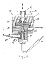
- Fig. 2 shows another embodiment.
- a housing 30 is provided with a compressed air supply coming from the control valve 10 in FIG. 1.
- the housing also has a compressed air outlet 32, which leads to a starter burner, not shown, designed as an injection atomizer. This starter burner is used to heat an evaporator upstream of the main burner.
- a membrane 33 is arranged in the housing 30 and can be acted upon from one side by the compressed air supplied by the compressed air supply.
- a pin 34 is operatively connected to the membrane 33, which is mounted so as to be longitudinally displaceable and which bears against the valve body 38.
- the valve body 38 is mounted in a longitudinally displaceable manner in a valve housing 36 and is loaded by a valve spring 37.
- the valve body 38 corresponds to the valve body 18 in FIG. 1. It will therefore not be explained in more detail here.
- 39 is a fuel supply and 35 de fuel outlet. 40 is the thermal sensor already explained in FIG. 1.
- the control valve shown in FIG. 1 is rotated into a position in which the auxiliary burner designed as an injection atomizer is supplied with compressed air.
- This compressed air is fed to the valve housing 30 and fed from here to the starter burner.
- the membrane 33 is acted upon and thereby moves the pin 34 against the valve body 38, whereby this is displaced against the action of the spring 37, whereby the valve seat is opened and thus the fuel supply is released, so that the fuel is supplied to the starter or main burner via the control valve.
- the control valve 10 is switched on, whereby the compressed air supply to the auxiliary burner is interrupted. As a result, the membrane 33 is no longer acted upon by the compressed air. It returns to its rest position together with pin 34, causing the valve body. 38, which is held by the signal generated by the thermal sensor 40, is no longer in operative connection with the pin 34.
- the thermal sensor 40 cools and the valve body 38 is released and the fuel supply is closed.
Landscapes
- Engineering & Computer Science (AREA)
- Chemical & Material Sciences (AREA)
- Combustion & Propulsion (AREA)
- Mechanical Engineering (AREA)
- General Engineering & Computer Science (AREA)
- Feeding And Controlling Fuel (AREA)
- Spray-Type Burners (AREA)
Applications Claiming Priority (2)
| Application Number | Priority Date | Filing Date | Title |
|---|---|---|---|
| DE19883834094 DE3834094A1 (de) | 1988-10-07 | 1988-10-07 | Explosionssicherung fuer einen brenner |
| DE3834094 | 1988-10-07 |
Publications (2)
| Publication Number | Publication Date |
|---|---|
| EP0362487A2 true EP0362487A2 (fr) | 1990-04-11 |
| EP0362487A3 EP0362487A3 (fr) | 1991-07-17 |
Family
ID=6364560
Family Applications (1)
| Application Number | Title | Priority Date | Filing Date |
|---|---|---|---|
| EP19890112335 Withdrawn EP0362487A3 (fr) | 1988-10-07 | 1989-07-06 | Dispositif de sécurité contre les explosions pour un brûleur |
Country Status (2)
| Country | Link |
|---|---|
| EP (1) | EP0362487A3 (fr) |
| DE (1) | DE3834094A1 (fr) |
Family Cites Families (3)
| Publication number | Priority date | Publication date | Assignee | Title |
|---|---|---|---|---|
| US2515229A (en) * | 1947-05-06 | 1950-07-18 | Domestic Thermostat Company | Combined manual, thermostatic, and safety valve unit in burner systems |
| NL6509971A (fr) * | 1965-08-02 | 1967-02-03 | ||
| DE8423948U1 (de) * | 1984-08-11 | 1987-12-03 | Haas + Sohn - Sinn Haus- und Kochtechnik GmbH, 6349 Sinn | Mit flüssigem Brennstoff gespeister Druckverdampfungsbrenner |
-
1988
- 1988-10-07 DE DE19883834094 patent/DE3834094A1/de not_active Withdrawn
-
1989
- 1989-07-06 EP EP19890112335 patent/EP0362487A3/fr not_active Withdrawn
Also Published As
| Publication number | Publication date |
|---|---|
| EP0362487A3 (fr) | 1991-07-17 |
| DE3834094A1 (de) | 1990-04-12 |
Similar Documents
| Publication | Publication Date | Title |
|---|---|---|
| DE3139880C2 (de) | Zündeinrichtung | |
| DE69428704T2 (de) | Zündapparat und ein heizwerkzeug | |
| DE3526927A1 (de) | Heizkolben zum betrieb mit fluessiggas | |
| DE2846916C2 (de) | Sicherheitsvorrichtung für gasbetriebene Durchlauferhitzer mit einer Wassermangelsicherung | |
| DE102007024923B4 (de) | Sicherheitsmechanismus für einen Brenner | |
| DE2402313A1 (de) | Piezoelektrische brenneranzuender und systeme | |
| DE4234489C2 (de) | Gasfeuerzeug mit zwei Brennern | |
| DE2608805C2 (de) | Zündvorrichtung für eine Gaslampe | |
| DE102007024924B4 (de) | Sicherheitsmechanismus für einen Brenner | |
| EP1599694B1 (fr) | Dispositif de regulation de gaz | |
| EP0362487A2 (fr) | Dispositif de sécurité contre les explosions pour un brûleur | |
| DE3500009A1 (de) | Haushaltsgasanzuender | |
| DE2104093A1 (de) | Elektrische Zündvorrichtung zum Anzünden von Zigarren und Zigaretten | |
| DE69814914T2 (de) | Automatisch ausschaltbare klebstoffpistole | |
| DE1949518A1 (de) | Feuerzeug oder Anzuender mit piezoelektrischer Zuendvorrichtung und Verfahren zur Zuendung derselben | |
| DE3515464A1 (de) | Betriebssteuereinrichtung in einer brennapparatur | |
| DE960531C (de) | Sicherungsvorrichtung fuer Gasfeuerungsanlagen | |
| DE10112667C2 (de) | Vorrichtung zum Zuführen von Gas bei einem Gas-Wassererhitzer | |
| DE919041C (de) | Sicherheitsvorrichtung fuer Gasbrenner | |
| DE7007505U (de) | Zuendeinrichtung fuer gasbrenner. | |
| DE1802931B2 (de) | Elektrischer Zigarrenanzünder | |
| DE725227C (de) | Sicherheitszuendvorrichtung fuer Gasbrenner | |
| DE7935068U1 (de) | Gasbeheiztes geraet | |
| DE838047C (de) | Sicherheitsvorrichtung für Gasfeuerstätten | |
| AT151989B (de) | Zündeinrichtung für Gase aller Art. |
Legal Events
| Date | Code | Title | Description |
|---|---|---|---|
| PUAI | Public reference made under article 153(3) epc to a published international application that has entered the european phase |
Free format text: ORIGINAL CODE: 0009012 |
|
| AK | Designated contracting states |
Kind code of ref document: A2 Designated state(s): AT DE ES FR IT NL |
|
| PUAL | Search report despatched |
Free format text: ORIGINAL CODE: 0009013 |
|
| AK | Designated contracting states |
Kind code of ref document: A3 Designated state(s): AT DE ES FR IT NL |
|
| STAA | Information on the status of an ep patent application or granted ep patent |
Free format text: STATUS: THE APPLICATION IS DEEMED TO BE WITHDRAWN |
|
| 18D | Application deemed to be withdrawn |
Effective date: 19920103 |