EP0362538A1 - Procédé pour mélanger les fibres textiles - Google Patents
Procédé pour mélanger les fibres textiles Download PDFInfo
- Publication number
- EP0362538A1 EP0362538A1 EP89115630A EP89115630A EP0362538A1 EP 0362538 A1 EP0362538 A1 EP 0362538A1 EP 89115630 A EP89115630 A EP 89115630A EP 89115630 A EP89115630 A EP 89115630A EP 0362538 A1 EP0362538 A1 EP 0362538A1
- Authority
- EP
- European Patent Office
- Prior art keywords
- fiber
- mixture
- component
- fibers
- removal
- Prior art date
- Legal status (The legal status is an assumption and is not a legal conclusion. Google has not performed a legal analysis and makes no representation as to the accuracy of the status listed.)
- Granted
Links
Images



Classifications
-
- D—TEXTILES; PAPER
- D01—NATURAL OR MAN-MADE THREADS OR FIBRES; SPINNING
- D01G—PRELIMINARY TREATMENT OF FIBRES, e.g. FOR SPINNING
- D01G99/00—Subject matter not provided for in other groups of this subclass
-
- D—TEXTILES; PAPER
- D01—NATURAL OR MAN-MADE THREADS OR FIBRES; SPINNING
- D01G—PRELIMINARY TREATMENT OF FIBRES, e.g. FOR SPINNING
- D01G13/00—Mixing, e.g. blending, fibres; Mixing non-fibrous materials with fibres
Definitions
- the invention relates to a method for mixing textile fibers according to the preamble of the first claim.
- the previous methods of mixing consist either in that fiber bales from different provenances are placed in a row and removed by means of a removal device which moves back and forth over them, in which fiber flakes are removed from the surface and transferred to a means of transport, or therein that parts of fiber bales are lifted manually or mechanically and fed one after the other on a conveyor belt to an opening machine in which these parts are broken down into fiber flakes and transferred to a means of transport.
- Such means of transport can be mechanical or pneumatic and convey the fiber flakes into so-called mixing boxes, in which the delivered fibers are filled in as a flake mixture.
- This mixing box becomes the fiber flake mixture placed on a collective transport at different speeds in order thereby to obtain a doubling effect in order to strive for homogenization of the fiber fluff mixture.
- the disadvantage of the first mentioned removal and mixing process is, however, that the mixture, due to the stationary rows of bales, is unchangeable until such a row has been completely removed, so that the mixing ratio remains the same throughout this time, during the second removal and mixing process additionally has the inaccuracy of the quantity withdrawn. It was therefore the task to create precise and homogeneous fiber mixtures, which can also be changed quickly as required.
- the object is achieved according to the invention in that fiber mixture components are formed, each with predetermined different fiber properties, which are each mixed together with controllable, variable component proportions to form a component mixture and in that this component mixture is dependent on predetermined or determined, changed properties of a subsequent intermediate product, e.g. a card sliver or an end product, e.g. of a yarn is determined or corrected.
- a subsequent intermediate product e.g. a card sliver or an end product, e.g. of a yarn is determined or corrected.
- fiber properties which are obtained in advance by taking samples from the fiber ball len be determined, mixed exactly in the desired mass in order to obtain the desired properties of an intermediate product, for example a card sliver or an end product, for example a yarn.
- FIG. 1 shows a number of conveyor belts 1 for receiving fiber bales 2 which are removed by fiber bale removal elements 3.
- the respective fiber bale removal member moves on stationary rails which are arranged, for example, in the diagonal direction of the fiber bales 2 located on the conveyor belt.
- Such a device is known in principle from the applicant's Swiss Patent No. 503809.
- the device shown and described in the applicant's Swiss patent application with the number 00399 / 88-8 could be used, in which the removal member 3 is attached to a removal device (not shown) that can be moved back and forth along horizontal bales 2 along the bale 2, can be moved up and down, as well as tilted for diagonal removal.
- the removal rate in both removal devices can be controlled by changing the displacement speed of the fiber bale removal member 3 along the above-mentioned diagonal path, as well as by changing the feed speed of the fiber bale 2 by means of a variable speed of the individual conveyor belt 1.
- the fiber flakes detached from the removal drum 4 are pneumatically in a manner known per se cal delivery line 5, which is not described here, transported away.
- the fiber flakes are conveyed into a mixer 6 and mixed therein to form a uniform mixture.
- the quantities conveyed into the mixer 6 by means of these individual pneumatic conveying lines 5 are referred to hereinafter as fiber flake components or simply components.
- Batch mixers or continuous mixers can be used as mixers; depending on the quantities mentioned are individual weight batches (kg) or a running quantity per unit of time (kg / h).
- the delivery lines 5 in FIG. 1 schematically open directly into the mixer 6, which is also shown schematically, but in practice this can vary depending on the type of mixer.
- air-fiber separators can be used to separate the respective fiber-air mixture from one another, so that the fiber flakes can fall into the mixer in free fall, while the air can be led into an exhaust air line.
- Such separators are well known from practice and are therefore not shown here in particular.
- the stated quantities of the aforementioned individual fiber flake components which are added to the mixer 6 are controlled by a controller 7 on the basis of a control program.
- Such a control program can be a computer program be, which has a component mixing program that adapt to adapt to changes in the mixture, respectively. is changeable.
- Another variant would be a digital control for each component, in which the performance of the individual components was selected manually. could be changed.
- the functions relevant to the removal performance of the components e.g. the feed speed of the respective conveyor belt 1 or the removal movement of the fiber bale removal member 3 is controlled by one or the other controller.
- the pneumatic conveying lines do not have to convey the removed product directly into the mixer, but that mechanical conveying elements are interposed, for example conveyor belts.
- the fiber air separators mentioned place their fiber product in such mechanical conveying elements.
- Each fiber removal member 3 is connected to the controller 7 via a control line 8 and each conveyor belt 1 via a control line 19.
- Figure 2 shows a variant of Figure 1, but in which the same elements have the same reference numerals.
- the pneumatic conveyor lines 5 promote the removed fibers.
- Fiber flakes, also called product, are not directly in the mixer 6 but in component cells 9, from which the product filled therein is in each case discharged by means of a discharge device 10 and is fed into the mixer 6 by means of a subsequent metering device 11.
- the discharge rate from the individual component cells 9 is controlled by a controller 7.1, which controls the individual metering devices 11 and 11 by means of control lines 12. as a variant, the discharge apparatus 10 controlled.
- the metering devices 11 can each be controlled by means of a control line 13 via the dispensing devices 10 in order to coordinate the dispensing with the metering.
- the discharge devices could also be controlled directly by the controller 7.1.
- the component cells 9 are filled by the elements 1 to 5 already mentioned for FIG. 1, the use of two rows of fiber bales, each with the elements 1 to 4, being chosen only as an example. In practice, several rows of fiber bales or just a single row per component cell 9 could also be selected. Such a decision depends on the number or mix of provenances per row of bales, which are to form a mixed component to be placed in a corresponding cell 9.
- the filling up of the component cells 9 is, for example, by full provided in each cell level indicator 14 and controlled by vacancy indicator 15 by means of a controller 16.
- the control 16 for the reciprocating movement of the removal elements 3 is connected by control lines 17 each to the fiber bale removal elements 3 and by control lines 18 each to the drive motors of the conveyor belts 1.
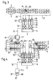
- FIG. 3 shows a further embodiment in which the same elements already shown and described with FIG. 2 have the same reference numerals. This applies to the fiber bales 2, the component cells 9, the discharge apparatus 10, the metering apparatus 11, the mixer 6 as well as the control 7.1 and the control lines 12 and 13.
- the fiber bales 2 which are here directly on the floor, these are also set up in groups which correspond to the respective provenance of the fiber bales.
- the removal is done by a mobile fiber bale removal device 20, which runs along the fiber bale groups and from the surface of fibers or. Removes fiber flakes.
- a mobile fiber bale removal device 20 which runs along the fiber bale groups and from the surface of fibers or. Removes fiber flakes.
- Such a device is known in the spinning industry under the name "Unifloc" and is sold by the applicant worldwide.
- this fiber bale removal device 20 conveys the removed fibers via a pneumatic conveying line 21 into the corresponding component cells 9.
- This control is via a control line 24 connected to the fiber bale removal device 20 and controls the removal of the corresponding fiber bale groups of fiber flakes for filling up the corresponding component cells 9.
- the fiber bale removal device 20 has a fiber removal member 23 which is known per se from the Unifloc and which removes the fibers from the bale surfaces by means of a removal drum (not shown) rotating therein.
- the fiber bale removal member 22 can be rotated by 180 degrees indicated by the arrows M, so that the fiber bale removal member can remove the fiber bale group 2 on the opposite side. This enables either one of the opposite fiber bale groups to be used as a reserve fiber bale group, or that with an automatic rotation of the fiber bale removal device 20 mentioned above, both opposite bale rows can be removed with a predetermined variation.
- FIG. 4 shows a variant of FIG. 3, so that the elements already described and shown with FIG. 3 have the same reference numerals.
- control is with 22.1 instead of with 22 characterized, since four individual fiber bale removal devices 20 are each to be controlled separately by means of the corresponding control line 24.
- a pneumatic conveying line is provided for each fiber bale removal device 20, which is accordingly identified with 21.1 instead of 21 and each opens into a component cell 9.
- FIG. 5 shows an arrangement similar to FIG. 1, in which instead of the single conveyor belt 1 per bale group of FIG. 1, a conveyor belt 30 with a purely conveying function and a conveyor belt 31 with a conveying / weighing function is provided per fiber bale group.
- the weighing function of the latter conveyor belt can be provided, for example, by supporting the axes of the deflecting rollers of the conveyor belt 31 on pressure sockets 32 known per se, each of which emits a signal 33 corresponding to the weight, which signal is sent via a control line 33 to a controller 7.2 processing the signals is forwarded.
- the processing of the aforementioned signals consists in that the controller 7.2 uses these to generate the control signals which control the motors of the conveyor belts 30 and 31 mentioned and the removal elements 3 via control lines 34.
- controller 7.2 controls the fiber removal elements 3 and the conveyor belts 30 and 31 at predetermined speeds in order to remove fibers from the fiber bales 2, which are conveyed into the mixer 6 by means of pneumatic conveyor lines 5.
- Each fiber bale removal member 3 of the individual fiber bale groups conveys a predetermined amount, controlled by the control 7.2, into the mixer 6.
- This predetermined amount to be removed (bp / h) per bale group is monitored and monitored by the respective weighing conveyor belt 31 or by the pressure dose weighing device 31 converted into signals and delivered to the controller via the control lines 33. If the quantity (kg / h) removed per fiber bale group does not match the specified quantity, the control adjusts the quantity to be removed until it matches the specified quantity.
- Measurements are always made via the measuring device 32 when the fiber bale removal member is at a standstill for a brief moment at the turning point of the back and forth removal path.
- the fiber bale removal member 3 always moves back and forth on the same path, essentially lying in the diagonal of the fiber bale to be removed. back and forth.
- the amount (kg / h) of the fibers to be removed from the bales is generated by means of the feed speed of the conveyor belts 30 and 31 and removal member 3.
- the controller 7.2 can be an electronic controller be based on the analog technology or a microprocessor, by means of which the different quantities removed per bale group can be set and adapted by the signals of the control lines 33 and input signals explained later.
- FIGS. 6 and 7 show a weighing system similar to FIG. 5, FIG. 7 being a plan view of FIG. 6, in the direction of the arrow A.
- bale groups that are arranged side by side and each form a mixing component.
- the fiber bales 2 each lie on a conveyor belt 40 and a weighing conveyor 41 connected to it.
- Each weighing conveyor 41 can be supported, analogously to the weighing conveyor 31 in FIG. 5, on pressure measuring cells 42, of which a signal corresponding to the weight is used a control line 43 is delivered to a controller 44.
- the fiber bales 2 located on the weighing conveyor belt 41 are removed by fiber bale removal device 48 in accordance with Swiss Patent Application No. 00399 / 88-8, which has already been mentioned in connection with FIG.
- the difference essentially consists in a long fiber bale removal member 49, which extends over the predetermined number of bale rows, with a removal drum 51 which simultaneously removes fibers from all of the predetermined bale rows shown in FIG. 7.
- the fiber removal member 49 removes in an oblique removal path, which essentially corresponds to the diagonal of a predetermined number of fiber bales 2 lined up, for example, as shown in FIGS. 6 and 7, of four fiber bales 2.
- bales can also be removed obliquely in this way, for example only one, as is shown with FIGS. 1 and 2.
- the fiber material removed by the fiber removal member 49 is conveyed in a pneumatic conveying line 50 which, according to the invention, opens into a continuous mixer 45.
- the conveying line 50 can end in a separator (not shown) which discharges the product into the mixer 45 .
- the fiber bale removal device 48 is controlled by the controller 44 via the control line 46 with respect to the driving speed.
- Another control line 47 is used to control the drive motors of the deflection rollers of the control belts 40 and 41.
- the deflecting rollers of the conveyor belts 40 and 41 have a separate drive motor for each bale group sen, ie that each motor has a control line 47 to the controller 44 separately.
- the controller 44 controls the back and forth movement of the fiber bale removal device 48 along the bales located on the weighing conveyor 41 and the up and down movement of the fiber bale removal member 49 on the device 48 during the aforementioned back and forth movement, so that the fiber bale as shown in FIG. 6 be removed in an inclined direction substantially corresponding to the diagonal of the four bales 2.
- This removal movement always runs in the same path and at a predetermined speed, so that the removal amounts (kg / h) of the individual fiber bale groups can be selected differently by the individual feed speeds of the conveyor belts 40 and 41.
- These different feed speeds of the individual bale groups correspond to a removal program with different amounts (kg / h) of the individual bale groups to be removed in order to obtain the mixture mentioned.
- the drive motors for the conveyor belts 40 and 41 are advantageously drum motors which are installed in the deflection rollers of the conveyor belts. Such drum motors can be operated at different frequencies by means of frequency inverters, i.e. are driven at different speeds, which is part of the controller 44.
- the controller 44 can be an analog or digital controller by means of wel the quantities of the individual components are controlled. These quantities are corrected by means of the pressure measuring cell signals, which are input through the control line 43 of the control 44, if the individual component quantity does not correspond to the target specification.
- FIG. 8 shows an extension of the previously described method, in which it is shown that after the mixer 6, the product coming from this mixer is put into a so-called blowroom 60, in which cleaning machines known per se are used.
- the blowroom 60 can contain so-called coarse cleaning machines 61 and fine cleaning machines 62. This blowroom, like the previous one, is only shown schematically.
- the card 63 following the blowroom which can be a card known per se, for example the card C4 sold worldwide by the applicant.
- This card 63 is provided with a control 64, which is known per se and controls the card functions, which, among other functions, also has the function of ensuring the uniformity and the amount (kg / h) of the card sliver.
- the card sliver is checked by a color sensor 65 and by a sensor for measuring the fiber fineness 66.
- the color testing device 65 outputs a signal 67 corresponding to the color of the card sliver and the fiber fineness testing device 66 outputs a signal 68 corresponding to the fiber fineness to the control devices 7; 7.1; 7.2; 44 mentioned in connection with FIGS. 1 to 7 , which each control the control of the individual fiber components.
- a further signal 81 corresponding to the card sliver quantity (kg / h) is also sent from the card control 64 to the controls 7; 7.1; 7.2; 44 entered.
- the product discharged from the mixer 6 is conveyed to the blowroom 60 via a conveyor system 69 and to the card 63 from the blowroom 60 via a conveyor system 70.
- Such conveyor systems can be mechanical or pneumatic, it is also known per se that conveyor systems exist between fine cleaning and coarse cleaning machines.
- the method according to the invention is likewise not restricted to a single blowroom 60 and a single card 63 after the mixer 6, but a plurality of blowrooms 60 can either be after the mixer 6 and several cards 63 are loaded with the product of the mixer 6 or if a blowroom is provided after the mixer 6, several cards 63 can be loaded with the product of the blowroom 60.
- a color test device 65 and / or a fiber fineness test device 66 can optionally be provided after each card, or there is also the possibility if several cards process the same product, that only one so-called guide card has these latter two test devices.
- FIG. 9 shows the possibility of providing the blowroom 60 between the fiber removal and the component cells 9, so that an already cleaned fiber material in the component cells 9 is available for the mixture.
- the conveying device from the fiber bale removal device 20 to the blowroom 60 basically corresponds to the pneumatic conveying line 21, whereby in this case too pneumatic conveyance is not mandatory but can be mechanical.
- the conveyor between the blowroom 60 and the component cells 9 can also be a pneumatic conveyor line, as indicated at 21, but it can be any conveyor system.
- the method according to the invention is not restricted to any conveyor system.
- blowroom 60 is not restricted to the combination with the arrangement from FIG. 3. It is understood that everybody's fiber components arrangements shown in the figures, with the exception of FIGS. 6 and 7, can first be cleaned and then get into the mixer 6. It is only a matter of effort, since a cleaning shop must be provided for each of the components in FIGS. 1, 2, 4 and 5.
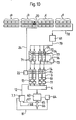
- FIG. 10 shows a variant of the method of FIG. 9, in that the blow room is divided into a rough cleaning with the cleaning machines 61 and one into a fine cleaning with the fine cleaning machines 71, each of which is preceded by a storage container 72 (for the sake of simplicity only one is marked).
- the fine cleaning machines 71 are started or stopped by a controller 73, namely stopped on the basis of a vacancy indicator 74 and started on the basis of a full status indicator 75 (only one identified in each case). These full and vacancy detectors emit their signals to the control 73 via the lines 76 and 77.
- the coarse cleaning machines 61 are fed by means of a fiber transport 78, which can correspond to the pneumatic conveying line 21 from FIG. 9 or to any fiber conveying known per se.
- the fine cleaning machines each pass their products on to a component mixing cell 9, as has already been described for FIGS. 2 to 4 and for FIG. 9.
- the components are cleaned individually, accordingly, the vacancy detectors 15 of the individual component cells 9 request the removal of fibers from the corresponding fiber bale group a or b or c or d in order to clean these removed fibers in the coarse cleaning machine and pass them on to the corresponding storage container 72 , which delivers the specified component to the subsequent fine cleaning machines 71.
- This product request by the empty detector 15 occurs because the corresponding fine cleaning machine no longer supplied a product, since the empty space detector 74 in the storage container 72 had also reported empty space.
- the corresponding group a to d is removed until the corresponding fullness indicator 75 reports fullness to the removed component.
- the corresponding fine cleaning machine can thus be put into operation again until the fullness detector 14 reports fullness again to the corresponding component cell 9.
- the fiber transport 80 between the mixer 6 and the card 63 can correspond to a fiber transport which is identified and described as 70 in FIG.
Landscapes
- Engineering & Computer Science (AREA)
- Textile Engineering (AREA)
- Preliminary Treatment Of Fibers (AREA)
Priority Applications (1)
| Application Number | Priority Date | Filing Date | Title |
|---|---|---|---|
| EP94112175A EP0628646A3 (fr) | 1988-09-06 | 1989-08-24 | Procédé de mélange des fibres textiles. |
Applications Claiming Priority (2)
| Application Number | Priority Date | Filing Date | Title |
|---|---|---|---|
| CH333588 | 1988-09-06 | ||
| CH3335/88 | 1988-09-06 |
Related Child Applications (1)
| Application Number | Title | Priority Date | Filing Date |
|---|---|---|---|
| EP94112175.8 Division-Into | 1994-08-04 |
Publications (2)
| Publication Number | Publication Date |
|---|---|
| EP0362538A1 true EP0362538A1 (fr) | 1990-04-11 |
| EP0362538B1 EP0362538B1 (fr) | 1995-03-01 |
Family
ID=4253747
Family Applications (2)
| Application Number | Title | Priority Date | Filing Date |
|---|---|---|---|
| EP89115630A Expired - Lifetime EP0362538B1 (fr) | 1988-09-06 | 1989-08-24 | Procédé pour mélanger les fibres textiles |
| EP94112175A Withdrawn EP0628646A3 (fr) | 1988-09-06 | 1989-08-24 | Procédé de mélange des fibres textiles. |
Family Applications After (1)
| Application Number | Title | Priority Date | Filing Date |
|---|---|---|---|
| EP94112175A Withdrawn EP0628646A3 (fr) | 1988-09-06 | 1989-08-24 | Procédé de mélange des fibres textiles. |
Country Status (10)
| Country | Link |
|---|---|
| US (1) | US5025533A (fr) |
| EP (2) | EP0362538B1 (fr) |
| JP (1) | JPH02139427A (fr) |
| CN (1) | CN1041013A (fr) |
| AU (1) | AU629231B2 (fr) |
| CS (1) | CS505589A2 (fr) |
| DD (1) | DD284705A5 (fr) |
| DE (1) | DE58909054D1 (fr) |
| RU (1) | RU2037572C1 (fr) |
| ZA (1) | ZA896176B (fr) |
Cited By (5)
| Publication number | Priority date | Publication date | Assignee | Title |
|---|---|---|---|---|
| WO1991016480A1 (fr) * | 1990-04-25 | 1991-10-31 | Siegfried Peyer Ag | Procede pour l'optimisation de la qualite des fibres |
| EP0402940A3 (fr) * | 1989-06-16 | 1992-01-08 | Maschinenfabrik Rieter Ag | Procédé de mélange de fibres textiles |
| EP0483607A1 (fr) * | 1990-11-02 | 1992-05-06 | Maschinenfabrik Rieter Ag | Procédé pour identifier la qualité d'un matériau fibreux |
| US5329668A (en) * | 1991-06-12 | 1994-07-19 | Trutzschler Gmbh & Co. Kg | Method and apparatus for detaching and mixing fiber tufts |
| US5509179A (en) * | 1990-06-25 | 1996-04-23 | Mondini; Giancarlo | Autoleveller draw frame having process feed back control system |
Families Citing this family (34)
| Publication number | Priority date | Publication date | Assignee | Title |
|---|---|---|---|---|
| DE3933274A1 (de) * | 1989-10-05 | 1991-04-18 | Hollingsworth Gmbh | Mehrballenoeffner |
| DE4025908A1 (de) * | 1989-10-05 | 1991-04-18 | Hollingsworth Gmbh | Mehrballenoeffner |
| JP3359935B2 (ja) * | 1991-08-28 | 2002-12-24 | ツリュツラー ゲゼルシャフト ミット ベシュレンクテル ハフツング ウント コンパニー コマンディトゲゼルシャフト | 木綿、化学繊維などからなる繊維俵を準備する方法及び装置 |
| DE59711965D1 (de) | 1996-05-20 | 2004-11-04 | Rieter Ag Maschf | Anlage zum Verarbeiten von Fasern |
| DE19630018A1 (de) * | 1996-07-25 | 1998-01-29 | Rieter Ag Maschf | Anlage zum Verarbeiten von Fasern |
| GB9800089D0 (en) * | 1998-01-06 | 1998-03-04 | Lockwood Keith M | Yarn manufacture and products |
| US6065277A (en) * | 1998-05-15 | 2000-05-23 | Tuscarora Yarns, Inc. | Process for producing dyed spun cotton yarns having improved uniformity, physical properties, and luster and yarns thus produced |
| US20090126119A1 (en) * | 2000-03-13 | 2009-05-21 | L&P Property Management Company, A Delaware Corporation | Fire resistant insulator pad |
| US20070202294A1 (en) * | 2000-03-13 | 2007-08-30 | L&P Property Management Company | Protective fire retardant component for a composite furniture system |
| BR0114034A (pt) * | 2000-09-01 | 2004-06-08 | Raymond Keith Foster | Aparelho para distribuição de aglomerações de fibras têxteis e método para dispersão e mistura de aglomerações de fibras têxteis |
| US6393665B1 (en) * | 2000-09-01 | 2002-05-28 | Raymond Keith Foster | Method and apparatus for mixing textile fibers and particulate materials |
| US6442803B1 (en) * | 2001-02-14 | 2002-09-03 | Raymond Keith Foster | Method of producing blends of cotton lint |
| US6715191B2 (en) | 2001-06-28 | 2004-04-06 | Owens Corning Fiberglass Technology, Inc. | Co-texturization of glass fibers and thermoplastic fibers |
| US7329043B2 (en) * | 2003-11-04 | 2008-02-12 | L&P Property Management Company | Thermal properties testing apparatus and methods |
| CN100402717C (zh) * | 2004-08-02 | 2008-07-16 | 吕恒正 | 混棉机组 |
| US20070006383A1 (en) * | 2005-07-06 | 2007-01-11 | Ogle Steven E | Mattress with substantially uniform fire resistance characteristic |
| CN100425747C (zh) * | 2006-01-06 | 2008-10-15 | 浙江华孚色纺有限公司 | 一种色纺专用混色机及其混合方法 |
| US8454795B1 (en) | 2006-12-05 | 2013-06-04 | Mark J. Henderson | System and method for producing bonded fiber/cellulose products |
| WO2008097776A1 (fr) * | 2007-02-09 | 2008-08-14 | United Feather & Down, Inc. | Fibre mélangée contenant de l'argent, matériau de remplissage mélangé contenant des fibres d'argent et procédé de production de ceux-ci |
| CN101358389B (zh) * | 2007-07-31 | 2010-12-15 | 浙江华孚色纺有限公司 | 色纺混纺专用预混机 |
| US8474115B2 (en) * | 2009-08-28 | 2013-07-02 | Ocv Intellectual Capital, Llc | Apparatus and method for making low tangle texturized roving |
| CN102041587B (zh) * | 2011-01-07 | 2013-03-20 | 青岛东佳纺机(集团)有限公司 | 联合混色机 |
| CN102978749B (zh) * | 2012-12-06 | 2015-10-28 | 绍兴国周纺织新材料有限公司 | 色纺纱混棉工艺 |
| BR112018006948B1 (pt) * | 2015-10-09 | 2022-07-19 | Ww Systems Ltda | Método para formar uma mistura homogeneizada de fardos de algodão para um processo de fiação |
| DE102015122807A1 (de) * | 2015-12-23 | 2017-06-29 | Temafa Maschinenfabrik Gmbh | Faserbearbeitungsanlage sowie Verfahren zum Öffnen und Mischen von Fasermaterial in einer Faserbearbeitungsanlage |
| CH712382A1 (de) * | 2016-04-21 | 2017-10-31 | Rieter Ag Maschf | Verfahren zum Betrieb eines Ballenöffners und Ballenöffner. |
| CN106637539B (zh) * | 2016-12-20 | 2018-10-23 | 绍兴柯桥南红纱业有限公司 | 多纤维混棉工艺 |
| DE102017102623A1 (de) * | 2017-02-09 | 2018-08-09 | TRüTZSCHLER GMBH & CO. KG | Verfahren und Anlage zur Bearbeitung von Fasern |
| CN108532033A (zh) * | 2018-06-01 | 2018-09-14 | 桐乡市建泰纺织有限公司 | 一种羊毛供料和毛机构 |
| CN108517586A (zh) * | 2018-06-01 | 2018-09-11 | 桐乡市建泰纺织有限公司 | 一种羊毛和毛装置 |
| CN108505148A (zh) * | 2018-06-01 | 2018-09-07 | 桐乡市建泰纺织有限公司 | 一种羊毛加料和毛装置 |
| CN110846745A (zh) * | 2019-12-14 | 2020-02-28 | 王其珍 | 一种纤维调色试制装置 |
| CN111764012A (zh) * | 2020-07-05 | 2020-10-13 | 安徽华茂纺织股份有限公司 | 一种差异化纤维品种防色差的方法 |
| CN115058798A (zh) * | 2022-06-23 | 2022-09-16 | 湖南津东云纺纺织有限公司 | 一种混纺均匀的色纺纱混棉装置 |
Citations (4)
| Publication number | Priority date | Publication date | Assignee | Title |
|---|---|---|---|---|
| CH481230A (de) * | 1966-12-24 | 1969-11-15 | Schubert & Salzer Maschinen | Verfahren und Vorrichtung zum selbsttätigen Mischen von Faserstoffkomponenten |
| US4009663A (en) * | 1974-09-20 | 1977-03-01 | Alex Jacques Keller | Apparatus for positioning bales within a bale assembly area |
| US4100651A (en) * | 1977-06-22 | 1978-07-18 | Aldrich Machine Works | Apparatus and method for removing and blending fibers from a plurality of fiber bales |
| DE3335763A1 (de) * | 1983-10-01 | 1985-04-18 | Trützschler GmbH & Co KG, 4050 Mönchengladbach | Verfahren und vorrichtung zum zuspeisen von fasermaterial zu einer mehrzahl von faserverarbeitungseinrichtungen |
Family Cites Families (9)
| Publication number | Priority date | Publication date | Assignee | Title |
|---|---|---|---|---|
| US2897548A (en) * | 1953-01-02 | 1959-08-04 | Johns Manville | Method and apparatus for opening and cleaning fibers |
| US2885741A (en) * | 1955-03-15 | 1959-05-12 | James Hunter Inc | Method and system of blending fibers |
| US2964802A (en) * | 1957-08-05 | 1960-12-20 | Toyo Boseki | Continuous production of slivers from textile fibres |
| IT1009799B (it) * | 1974-04-10 | 1976-12-20 | Marzoli E C Spa Flli | Metodo ed impianto di dosaggio per fibre tessili |
| DE2658044C3 (de) * | 1976-12-22 | 1980-02-21 | Truetzschler Gmbh & Co Kg, 4050 Moenchengladbach | Verfahren und Vorrichtung zum Erzeugen eines gleichmäßigen Faserbandes |
| EP0044408B1 (fr) * | 1980-07-23 | 1985-05-22 | Maschinenfabrik Rieter Ag | Procédé de surveillance d'une installation pour le mélange de fibres textiles et dispositif pour la mise en oeuvre de ce procédé |
| DE3513295C2 (de) * | 1985-04-13 | 1998-05-14 | Truetzschler Gmbh & Co Kg | Vorrichtung zum Abtragen von Faserballen |
| GB8524304D0 (en) * | 1985-10-02 | 1985-11-06 | Rieter Ag Maschf | Flock delivery systems |
| EP0226430A3 (fr) * | 1985-12-13 | 1988-03-23 | Unisearch Limited | Mesure de matière étrangère dans des confections de fibres |
-
1989
- 1989-08-04 AU AU39323/89A patent/AU629231B2/en not_active Ceased
- 1989-08-14 ZA ZA896176A patent/ZA896176B/xx unknown
- 1989-08-23 CN CN89106723A patent/CN1041013A/zh active Pending
- 1989-08-24 DE DE58909054T patent/DE58909054D1/de not_active Expired - Fee Related
- 1989-08-24 EP EP89115630A patent/EP0362538B1/fr not_active Expired - Lifetime
- 1989-08-24 EP EP94112175A patent/EP0628646A3/fr not_active Withdrawn
- 1989-08-30 US US07/400,693 patent/US5025533A/en not_active Expired - Fee Related
- 1989-08-31 CS CS895055A patent/CS505589A2/cs unknown
- 1989-09-05 RU SU894614967A patent/RU2037572C1/ru active
- 1989-09-05 DD DD89332380A patent/DD284705A5/de not_active IP Right Cessation
- 1989-09-06 JP JP1229478A patent/JPH02139427A/ja active Pending
Patent Citations (4)
| Publication number | Priority date | Publication date | Assignee | Title |
|---|---|---|---|---|
| CH481230A (de) * | 1966-12-24 | 1969-11-15 | Schubert & Salzer Maschinen | Verfahren und Vorrichtung zum selbsttätigen Mischen von Faserstoffkomponenten |
| US4009663A (en) * | 1974-09-20 | 1977-03-01 | Alex Jacques Keller | Apparatus for positioning bales within a bale assembly area |
| US4100651A (en) * | 1977-06-22 | 1978-07-18 | Aldrich Machine Works | Apparatus and method for removing and blending fibers from a plurality of fiber bales |
| DE3335763A1 (de) * | 1983-10-01 | 1985-04-18 | Trützschler GmbH & Co KG, 4050 Mönchengladbach | Verfahren und vorrichtung zum zuspeisen von fasermaterial zu einer mehrzahl von faserverarbeitungseinrichtungen |
Cited By (7)
| Publication number | Priority date | Publication date | Assignee | Title |
|---|---|---|---|---|
| EP0402940A3 (fr) * | 1989-06-16 | 1992-01-08 | Maschinenfabrik Rieter Ag | Procédé de mélange de fibres textiles |
| WO1991016480A1 (fr) * | 1990-04-25 | 1991-10-31 | Siegfried Peyer Ag | Procede pour l'optimisation de la qualite des fibres |
| CH681228A5 (fr) * | 1990-04-25 | 1993-02-15 | Peyer Ag Siegfried | |
| US5210909A (en) * | 1990-04-25 | 1993-05-18 | Siegfried Peyer Ag | Process for optimizing yarn quality |
| US5509179A (en) * | 1990-06-25 | 1996-04-23 | Mondini; Giancarlo | Autoleveller draw frame having process feed back control system |
| EP0483607A1 (fr) * | 1990-11-02 | 1992-05-06 | Maschinenfabrik Rieter Ag | Procédé pour identifier la qualité d'un matériau fibreux |
| US5329668A (en) * | 1991-06-12 | 1994-07-19 | Trutzschler Gmbh & Co. Kg | Method and apparatus for detaching and mixing fiber tufts |
Also Published As
| Publication number | Publication date |
|---|---|
| DE58909054D1 (de) | 1995-04-06 |
| AU3932389A (en) | 1990-03-15 |
| US5025533A (en) | 1991-06-25 |
| EP0362538B1 (fr) | 1995-03-01 |
| EP0628646A3 (fr) | 1995-02-08 |
| CS505589A2 (en) | 1991-09-15 |
| RU2037572C1 (ru) | 1995-06-19 |
| AU629231B2 (en) | 1992-10-01 |
| CN1041013A (zh) | 1990-04-04 |
| JPH02139427A (ja) | 1990-05-29 |
| ZA896176B (en) | 1991-01-30 |
| EP0628646A2 (fr) | 1994-12-14 |
| DD284705A5 (de) | 1990-11-21 |
Similar Documents
| Publication | Publication Date | Title |
|---|---|---|
| EP0362538B1 (fr) | Procédé pour mélanger les fibres textiles | |
| EP0641876B1 (fr) | Optimisation du nettoyage | |
| DE3233246C2 (de) | Verfahren zum Zuführen von abgewogenen Fasermengen zu einem Fördermittel | |
| EP0402940B1 (fr) | Procédé de mélange de fibres textiles | |
| US7614121B2 (en) | Apparatus for measuring the mass of fibre material passing through a spinning preparation machine or system | |
| CH659487A5 (de) | Verfahren und vorrichtung zum mischen von textilfasern. | |
| EP3177758B1 (fr) | Dispositif de mélange de composants fibreux | |
| DE2335814B2 (de) | Verfahren zur mischung von bestandteilen fuer die herstellung von span- faser - o.dgl. -platten aus mischgut unterschiedlicher eigenschaften vor deren dosiertem zufuehren zu einer schuttvorrichtung | |
| DE2031788A1 (de) | Verfahren und Vorrichtung zum kontinuierlichen Dosieren von Fasermatenal zur Vorlage an Spinnereimaschinen | |
| DE3731377C2 (fr) | ||
| EP1149196A1 (fr) | Melange de composants fibreux | |
| CH685708A5 (de) | Verfahren und Vorrichtung zum Abtragen und Mischen von Textilfasern, z.B. Baumwolle, Chemiefasern und dgl. | |
| DE102015122807A1 (de) | Faserbearbeitungsanlage sowie Verfahren zum Öffnen und Mischen von Fasermaterial in einer Faserbearbeitungsanlage | |
| US2851737A (en) | Blending of textile fibrous materials | |
| EP0149177A2 (fr) | Dispositif pour la préparation d'un mélange de fibres contenant des déchets de fibres longues pour la filature à bout libéré | |
| DE2559475A1 (de) | Anordnung zum steuern von auswerfern in sortieranlagen | |
| EP2342982A1 (fr) | Fabrication de tronçons de filtre et machine de tronçon de filtre | |
| DE3913733A1 (de) | Kastenspeiser mit waage | |
| EP0409772A1 (fr) | Procédé de traitement optimal des fibres textiles d'une provenance différente | |
| DE2504873A1 (de) | Anlage zum pneumatischen beschicken tabakverarbeitender strangmaschinen | |
| DE102008022817A1 (de) | Kontinuierliche Verwiegung von Faserflocken | |
| SU111670A1 (ru) | Автоматическа поточна лини дл выработки чесаной ленты из кипного или разрыхленного волокна в шерстопр дильном производстве | |
| DE1510277A1 (de) | Speisevorrichtung fuer vliesbildende Maschinen der Textil- bzw. Faserstoffindustrie | |
| DE8137585U1 (de) | Vorrichtung zum mischen von textilfasern | |
| DE1510275A1 (de) | Vorrichtung zur regelbaren Zufuehrung von Flocken od.dgl. von OEffnungs- und/oder Reinigungsmaschinen zur Speisung einer Mchrzahl von Kardenmaschinen u.dgl. |
Legal Events
| Date | Code | Title | Description |
|---|---|---|---|
| PUAI | Public reference made under article 153(3) epc to a published international application that has entered the european phase |
Free format text: ORIGINAL CODE: 0009012 |
|
| AK | Designated contracting states |
Kind code of ref document: A1 Designated state(s): CH DE FR GB IT LI |
|
| 17P | Request for examination filed |
Effective date: 19900504 |
|
| 17Q | First examination report despatched |
Effective date: 19911024 |
|
| GRAA | (expected) grant |
Free format text: ORIGINAL CODE: 0009210 |
|
| AK | Designated contracting states |
Kind code of ref document: B1 Designated state(s): CH DE FR GB IT LI |
|
| XX | Miscellaneous (additional remarks) |
Free format text: TEILANMELDUNG 94112175.8 EINGEREICHT AM 24/08/89. |
|
| REF | Corresponds to: |
Ref document number: 58909054 Country of ref document: DE Date of ref document: 19950406 |
|
| GBT | Gb: translation of ep patent filed (gb section 77(6)(a)/1977) |
Effective date: 19950330 |
|
| ITF | It: translation for a ep patent filed | ||
| ET | Fr: translation filed | ||
| PGFP | Annual fee paid to national office [announced via postgrant information from national office to epo] |
Ref country code: FR Payment date: 19950714 Year of fee payment: 7 |
|
| PLBE | No opposition filed within time limit |
Free format text: ORIGINAL CODE: 0009261 |
|
| STAA | Information on the status of an ep patent application or granted ep patent |
Free format text: STATUS: NO OPPOSITION FILED WITHIN TIME LIMIT |
|
| 26N | No opposition filed | ||
| PG25 | Lapsed in a contracting state [announced via postgrant information from national office to epo] |
Ref country code: FR Effective date: 19970430 |
|
| REG | Reference to a national code |
Ref country code: FR Ref legal event code: ST |
|
| PGFP | Annual fee paid to national office [announced via postgrant information from national office to epo] |
Ref country code: GB Payment date: 20010724 Year of fee payment: 13 |
|
| PGFP | Annual fee paid to national office [announced via postgrant information from national office to epo] |
Ref country code: CH Payment date: 20010726 Year of fee payment: 13 |
|
| PGFP | Annual fee paid to national office [announced via postgrant information from national office to epo] |
Ref country code: DE Payment date: 20010801 Year of fee payment: 13 |
|
| REG | Reference to a national code |
Ref country code: GB Ref legal event code: IF02 |
|
| PG25 | Lapsed in a contracting state [announced via postgrant information from national office to epo] |
Ref country code: GB Free format text: LAPSE BECAUSE OF NON-PAYMENT OF DUE FEES Effective date: 20020824 |
|
| PG25 | Lapsed in a contracting state [announced via postgrant information from national office to epo] |
Ref country code: LI Free format text: LAPSE BECAUSE OF NON-PAYMENT OF DUE FEES Effective date: 20020831 Ref country code: CH Free format text: LAPSE BECAUSE OF NON-PAYMENT OF DUE FEES Effective date: 20020831 |
|
| PG25 | Lapsed in a contracting state [announced via postgrant information from national office to epo] |
Ref country code: DE Free format text: LAPSE BECAUSE OF NON-PAYMENT OF DUE FEES Effective date: 20030301 |
|
| REG | Reference to a national code |
Ref country code: CH Ref legal event code: PL |
|
| GBPC | Gb: european patent ceased through non-payment of renewal fee |
Effective date: 20020824 |
|
| PG25 | Lapsed in a contracting state [announced via postgrant information from national office to epo] |
Ref country code: IT Free format text: LAPSE BECAUSE OF NON-PAYMENT OF DUE FEES;WARNING: LAPSES OF ITALIAN PATENTS WITH EFFECTIVE DATE BEFORE 2007 MAY HAVE OCCURRED AT ANY TIME BEFORE 2007. THE CORRECT EFFECTIVE DATE MAY BE DIFFERENT FROM THE ONE RECORDED. Effective date: 20050824 |