EP0362559B1 - Dispositif d'entraînement pour dispositif d'arrosage ou dispositif similaire - Google Patents
Dispositif d'entraînement pour dispositif d'arrosage ou dispositif similaire Download PDFInfo
- Publication number
- EP0362559B1 EP0362559B1 EP89116235A EP89116235A EP0362559B1 EP 0362559 B1 EP0362559 B1 EP 0362559B1 EP 89116235 A EP89116235 A EP 89116235A EP 89116235 A EP89116235 A EP 89116235A EP 0362559 B1 EP0362559 B1 EP 0362559B1
- Authority
- EP
- European Patent Office
- Prior art keywords
- gear
- chamber
- rotor
- drive
- water
- Prior art date
- Legal status (The legal status is an assumption and is not a legal conclusion. Google has not performed a legal analysis and makes no representation as to the accuracy of the status listed.)
- Expired - Lifetime
Links
Images


Classifications
-
- B—PERFORMING OPERATIONS; TRANSPORTING
- B05—SPRAYING OR ATOMISING IN GENERAL; APPLYING FLUENT MATERIALS TO SURFACES, IN GENERAL
- B05B—SPRAYING APPARATUS; ATOMISING APPARATUS; NOZZLES
- B05B3/00—Spraying or sprinkling apparatus with moving outlet elements or moving deflecting elements
- B05B3/02—Spraying or sprinkling apparatus with moving outlet elements or moving deflecting elements with rotating elements
- B05B3/04—Spraying or sprinkling apparatus with moving outlet elements or moving deflecting elements with rotating elements driven by the liquid or other fluent material discharged, e.g. the liquid actuating a motor before passing to the outlet
- B05B3/0417—Spraying or sprinkling apparatus with moving outlet elements or moving deflecting elements with rotating elements driven by the liquid or other fluent material discharged, e.g. the liquid actuating a motor before passing to the outlet comprising a liquid driven rotor, e.g. a turbine
- B05B3/0432—Spraying or sprinkling apparatus with moving outlet elements or moving deflecting elements with rotating elements driven by the liquid or other fluent material discharged, e.g. the liquid actuating a motor before passing to the outlet comprising a liquid driven rotor, e.g. a turbine the rotation of the outlet elements being reversible
- B05B3/0438—Tubular elements holding several outlets, e.g. apertured tubes, oscillating about an axis substantially parallel to the tubular element
Definitions
- the invention relates to a drive device according to the preamble of claims 1, 7 and 11. It expediently has a liquid or flow drive, in particular in that at least part of the water to be discharged with the sprinkler is used to drive at least one movement of the sprinkler or the like .
- a liquid guide is provided in a housing, to which a drive rotor is exposed, which possibly performs the desired movement function via a gear, so that advantageous effects result.
- Such irrigation devices are generally known.
- the gear unit also runs continuously in a water bath.
- the gear unit can be mounted on a carrier fastened on a hollow axle directly behind the turbine wheel and can engage within the water-filled housing in an internal ring gear which is connected to the housing.
- the invention is further based on the object of avoiding disadvantages of known solutions and, in particular, of creating a drive device of the type mentioned which enables further improved functionality and in particular a particularly compact design.
- the features of claim 1 are suitable for achieving this object.
- the transmission is essentially shifted out of the water-bearing areas and preferably arranged in a separate transmission chamber, so that its output element, for example an output pinion, can be made accessible without any particular sealing problems and therefore in a space-saving manner for the drive engagement.
- contamination of the gearbox due to water contamination is avoided, and the gearbox runs particularly smoothly by means of a lubricant or by using self-lubricating materials for the gearwheels.
- the transmission is expediently arranged in a transmission chamber which is essentially circular in cross section and which can extend over an arc angle of less than 180, so that it takes up very little space.
- the gear chamber is expediently delimited on the outer circumference by a part of an axially symmetrical or approximately cylindrical housing shell and within this housing shell by, for example, an approximately flat intermediate wall which is approximately parallel to the housing axis, so that the remaining, possibly larger part of the interior of this housing shell for the water supply Available.
- the gear chamber is closed with transverse walls in which all gear axes can be held and which expediently go over the entire inside width of the housing shell, but are provided with corresponding openings in the area of the water-carrying chamber next to the gear for water passage.
- the last-mentioned water-carrying chamber which lies at least partially essentially in the same longitudinal section of the housing as the gear chamber, can furthermore be used for accommodating further functional parts of the drive device.
- a changeover valve or the like of a changeover device is preferably accommodated within this chamber, by means of which the drive rotor or the output pinion of the transmission can be driven alternately back and forth in both directions of rotation in that a changeover element is dependent on the rotation path by the movement generated by the drive device is converted.
- Said longitudinal section of the housing is thus subdivided into at least one drying chamber separated from the water supply and at least one water-carrying wet chamber, it being possible for appropriate functional parts to be accommodated in each chamber.
- a chamber accommodating the drive rotor expediently closes in the longitudinal direction of the housing directly to the longitudinal section mentioned, i.e. in the direction of the water flow, whereby this rotor chamber can be separated from the adjacent chambers next to each other by the associated, continuous transverse wall in which the drive rotor is also to be supported.
- the drive rotor is expediently mounted with a very thin shaft, which is mounted in a sealed manner in the transverse wall and is in drive engagement with the transmission within the transmission chamber.
- the drive rotor arranged axially parallel to the housing is eccentric with respect to the housing or the rotor chamber located in the housing axis, its outer diameter being correspondingly smaller than the inner width of the rotor chamber.
- the rotor axis of the drive rotor can be laid close to the transmission axes on the one hand, and on the other hand, drive nozzles or associated nozzle channels or the associated nozzle channels can be accommodated in a space-saving manner between the region of the housing shell which is further away from the outer circumference of the drive rotor and can be designed with a relatively large cross section.
- the axial extent of the rotor chamber need only be slightly larger than that of the drive rotor, while the axial extent of the cross-divided chambers adjoining in the longitudinal direction need only be approximately as large as the associated gear length.
- the housing can moreover have a smaller outer width than in the area of the gear chamber, so that the end chamber, which closes it, can be overlapped with an annular collar, the outer width of which is equal to that of the housing in the area of the gear chamber.
- the transmission expediently has a very high reduction ratio, so that the drive rotor can be operated at high speed.
- This reduction ratio and the sealed mounting of the drive rotor mean that the transmission can be essentially self-locking when it is driven from the side of its output pinion.
- an overload clutch is provided in the drive connection between the drive rotor and the component that is in drive engagement with the transmission, for example a carrier, stand or the like is designed in the manner of a slip clutch.
- the overload clutch has coupling members which mesh with one another under pressure in almost any relative position, but the teeth of which can jump over one another against the pressure in the event of overload.
- a shaft is advantageously provided which is detachably but essentially rigidly connected to the housing of the water motor and which swivels relative to the water motor. or rotatable carrier part axially secured against the water motor so that it can be surrounded on its outer circumference by the overload clutch. If this shaft is designed as a hollow shaft, it serves at the same time for the line connection between a hose connection or the like provided on the carrier and the housing of the water motor.
- the overload clutch can also be provided in drive devices other than those described.
- a further embodiment of the invention in particular a drive device of the type described, also results from the fact that the water flow entering the housing of the water motor, depending on the flow rate or the pressure, can at least partially be directed around the drive rotor such that the corresponding partial flow does not act on the drive rotor in the sense of the action of the drive, although this partial flow is passed through the rotor chamber and, for example, is only prevented from acting on the drive rotor by guide members.
- the partial flow is expediently controlled by at least one pressure relief valve between a water-conducting chamber lying to the side of the gear chamber and the rotor chamber, the valve closing part in the form of a simple plate in the rotor chamber being able to be resiliently pressed against a passage opening in such a way that it lifts off when a predetermined pressure is reached and releases the passage bypassing the valve channel or channels.
- Two valve closing parts are expediently formed by the tongue-like ends of a flat material strip which is fastened only approximately in the middle between these ends on the associated transverse wall and thereby forms two spring arms projecting in opposite directions and, with its ends, forms the valve closing parts.
- a drive device 1 for example, for pivoting a sprinkler device 2, which can be set up using a stand 3, an earth anchor or the like.
- the stand 3 has in the illustrated embodiment two V-shaped downward diverging, extending in the longitudinal direction of the sprinkler, approximately U-shaped stand 4, which are laterally inserted with their ends in two end supports 5, 6 and with these the console or form the fixed or immovable component of the irrigation device 2, on and between which a nozzle housing 7 is mounted as the movable component driven by the drive device 1.
- the nozzle housing 7 has on its upper side at least one longitudinal row of differently oriented spray nozzles 8, from which practically one type of water curtain emerges in one plane, which, as seen in the longitudinal direction, is inclined to the left and / or right by the pivoting movement and thereby has a base area of adjustable size, for example a lawn or a bed.
- the approximately cylindrical housing which is extended downward in the area of the drive device 1, has a bearing pin 9 which engages in a bearing opening of the associated carrier 6 at the front end remote from the drive device 1.
- the other end of the nozzle housing 7 forming the nozzle carrier is mounted in the associated carrier 5 with a hollow shaft 10 projecting beyond this end.
- the nozzle housing 7 expediently consists of two lateral half-shells made of plastic, which interlock with tongue and groove and are connected to one another in an essentially liquid-tight manner by ultrasonic welding or the like.
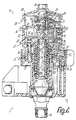
- the drive device 1 has, as the drive motor, a fluid-driven motor in the form of a water motor 11, which forms a self-contained structural unit with a housing 12, which essentially lies entirely within the nozzle housing 7 and only has a short rear end section for connecting the transmission to the carrier 5 protrudes from the rear end of the nozzle box 7.
- the lying housing axis 13 of the water motor 11 coincides with the axis of rotation or pivoting of the nozzle housing 7, the hollow shaft 10 being inserted firmly into the rear end of the housing 11 and being rotatably mounted in the carrier 5 made of plastic.
- a connection for a water pipe in the form of a hose connection is inserted into the associated end face of the carrier 5.
- a connection for a water pipe in the form of a hose connection preferably a plug-in coupling member of a quick coupling
- the interior of the housing 12 or the water motor 11 is supplied with pressurized water through the hollow shaft 10, which then exits again completely through a water outlet connection 15 provided at the front end of the housing 11.
- a angular pipe bend 16 is sealed with one end attached, the other end of which is inserted from below into a nozzle line 17 lying inside the nozzle housing 7.
- This nozzle line 17 extends in the longitudinal direction of the nozzle housing 7 continuously over all spray nozzles 8, such that these are connected together with the inner ends of their nozzle bores directly to the nozzle line 17, the cross sections of which are substantially or several times smaller than that of the nozzle housing 7.
- the housing 12 of the water motor 11 is inserted directly behind the nozzle line 17 centered in a receptacle 18 of the nozzle housing 7 and secured against rotation, for example, by cams engaging in the rear end wall of the nozzle housing 7.
- the receptacle 18 can be formed by a plurality of ribs or the like distributed over the circumference, which abut the outer circumference of the housing 12.
- a multi-stage, namely five to ten-stage, preferably eight-stage reduction gear 19 is provided, of which a first gear stage is formed by the input-side drive connection of the gear unit and a further gear stage is formed by the output-side drive connection can be.
- the gear 19 is provided in a gear chamber 20 of the housing 12 which is separated from the water supply between the hollow shaft 10 and the water outlet connection 15, the length of this gear chamber 20 being less than the outer diameter of the housing 12 in its area.
- a switching device 21 For alternating switching of the pivoting direction of the nozzle housing 7, a switching device 21 is provided, which by a Has pivoting movement between two control positions actuated switch valve 22.
- This changeover valve 22 is arranged in a changeover chamber 23, which is located in the same longitudinal section of the housing 12 as the transmission chamber 20, but is connected to the water guide between the hollow shaft 10 and the water outlet connection 15 or directly to the associated end of the hollow shaft 10.
- the water flowing through the water guide drives a drive rotor 24 of the hydraulic motor, this drive rotor 24 having a turbine wheel 25 exposed to at least one jet in a rotor chamber 26.
- This rotor chamber 26 is provided axially within the housing 12 immediately following the gear chamber 20 and the changeover chamber 23. However, the housing 12 has a smaller inner and / or outer diameter in the area of the rotor chamber 26 compared to the area of the gear chamber 20 and the changeover chamber 23.
- the rotor chamber 26 is supplied directly from the switching chamber 23 with the water flowing through, which then emerges from the rotor chamber 26 directly through the water outlet connection 15.
- the housing 12 consists essentially of two housing parts 27, 28 and an end cap 29, which are centered against one another in the axial direction and which are centered against one another by plugging into one another and are connected to one another in a watertight manner by ultrasonic welding or the like.
- the rear housing part 27 forms the end or end collar passing through the rear end of the nozzle housing 7, as well as the transmission chamber 20 and the switchover chamber 23 over the largest part of their axial extent.
- the front housing part 28 is inserted with its rear end, offset in the outer diameter, centered into the front end of the housing part 27, which is complementarily expanded in the inner diameter, and forms a transverse wall lying approximately at right angles to the housing axis 13 and formed in one piece with it at a short distance from the rear housing part 27 30, which tightly separates the rotor chamber 26 from the gear chamber 20 and spatially from the changeover chamber 23.
- the rear housing part 27 forms an end wall 31, which is formed in one piece with it, over which the said front collar projects to the rear and which carries the front end of the hollow shaft 10.
- the rear housing part 27 furthermore forms an intermediate wall 32 formed in one piece with it, which connects both to the end wall 31 and to the inner circumference of the housing shell of this housing part 27 on opposite sides and, after the front housing part 28 has been attached, also close to the associated side the transverse wall 30 connects.
- This for example approximately flat and parallel to an axial plane of the housing intermediate wall 32 is offset from this axial plane approximately by its thickness to the gear 19, so that the gear chamber 20 has a smaller volume than the switching chamber 23.
- a sleeve-shaped water inlet connection 33 protrudes into the housing in one piece with the end wall 31 over part of the height of the intermediate wall 32, this water inlet connection 33 partially penetrating the intermediate wall 32 formed with it, but only in the form of a circular segment in the region of its inner end face is open to the switching chamber 23 and closed to the gear chamber 20.
- the water inlet connection 33 has an internal thread, into which the hollow shaft 10 is screwed with an external thread provided at its front end in such a way that the end face is braced with respect to the closed part of the inner end of the water inlet connection 33.
- the turbine wheel 25 of the drive rotor 24 has a rotor shaft 34, which is inserted into a hub and has a diameter of only about 2 to 3 mm, the end of which protrudes beyond the rear end face of the turbine wheel 25 passes through a bearing sleeve 35 and in the bearing opening of this bearing sleeve 35 with an annular seal 36 is sealed.
- the further away from the turbine wheel 25 on the side of the bearing sleeve 35 and the rotor pinion 37 facing away from this end of the rotor shaft 34 can be mounted in a bearing eye of the transverse wall 30 protruding into the gear chamber 20, which engages in a corresponding cutout of the intermediate wall 32 and seals is precisely aligned and additionally supported.
- the gear 19 each has a cylindrical pin-shaped gear axis 39 or 40, each gear axis having its front end in the housing part 28 or in a blind hole in the transverse wall 30 and is held with its rear end in a blind hole in the housing part 27.
- a plurality of identical, stepped toothed wheels 41, 42, 43 is axial on each transmission axis 39, 40 arranged next to each other, with the smaller diameter gear stage of the one transmission axis driving the larger diameter gear stage of the other transmission axis.
- the larger diameter gear stage of a first gear 41 of the transmission axis 39 is driven directly by the rotor pinion 37, while a smaller diameter gear stage of the last gear 43 of the same transmission axis 39 forms an output gear 44 of the transmission 19, the diameter of which compared to the other, smaller gear stages is larger and protrudes through a window 47 over the inner circumference of an inner end collar 46, which lies concentrically within the end collar 45 which engages in the rear end wall of the nozzle housing 7.
- the two end collars 45, 46 are connected to one another via an approximately shell-shaped pinion housing which is formed in one piece with them and which over most of the circumference of the output pinion 44, namely except for the area projecting beyond the window 47 and also at covers the rear end face and forms a bearing projection projecting into a bearing opening of the driven pinion 44, in the blind hole of which the rear end of the gear axis 39 is held.
- the rear end of the gear axis 40 also extends over part of the axial extent of the front collar 46, the associated area of which is reinforced with a corresponding bearing eye for receiving this rear end.
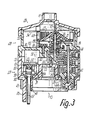
- the outer circumferences of the larger gearwheel stages of the gearwheels 41, 42, 43 which have the same diameter, extend up to close to the associated side of the intermediate wall 32 and close to the inner circumference of the casing of the housing 12 or the gearbox chamber 20, this jacket in the area of the gearbox chamber 20, as can be seen in particular in FIG. 3, is provided on the inner circumference for receiving the gearwheels with a recess in such a way that it is thinner in this area than in the other areas.
- two drive nozzles 48, 49 directed approximately tangentially in opposite directions against the circumference of the turbine wheel 25 are provided, one of which determines the direction of rotation in one direction and the other determines the direction of rotation in the opposite direction.
- the nozzle openings 48, 49 are connected to the changeover chamber 23 via lines approximately parallel to the axis of the housing 12, the nozzle channels 50, 51 both projecting freely from the transverse wall 30 into the changeover chamber 23 and from the transverse wall 30 to the front protrude approximately up to the end cap 29 into the rotor chamber 26.
- the parts of the nozzle channels 50, 51 projecting into the switchover chamber 23 are formed by two channel connections 52, which are symmetrical on both sides of the axial plane 38 and have an oblong cross-section in cross section, the central planes of which are approximately parallel to the axial plane 38 and are parallel to one another.
- the parts of the nozzle channels 50, 51 projecting into the rotor chamber 26 are formed by separate channel sections 53, each of which is connected to one of the channel connections 52 via a passage opening in the transverse wall 30 and which is connected to the reduced-diameter casing of the front casing 28 with its turbine wheel 25
- the sides of the channel sections 53 which face the rotor shaft 34 are closed up to the rear end face of the turbine wheel 25 and then open to form the nozzle openings of the drive nozzles 48, 49.
- the front ends of the channel sections 53 facing away from the transverse wall 30 are open before assembly of the end cap 29 and, when the end cap 29 is put on, are closed with end closures 54 which protrude in one piece from the inside of the end wall of the end cap 29, so that manufacture is very simple of the housing in plastic is possible.
- the switching device 21 or the switching valve 22 has a switching element 55 which is mounted for carrying out a control movement and which can be pivoted about a relatively small angle about an axis perpendicular to the housing axis, preferably in the axial plane 38, between two end positions and in FIG. 4 in its central position is shown.
- the switching member 55 has an approximately T-shaped rocker 56, the T-head web is located within the switching chamber 23 and the T-foot forms a movable the end wall 31, but sealed with an annular seal 58 so as to penetrate the switching pin 57 that the free end of the switching pin 57 protrudes rearward over the end collars 45, 46.
- the switching mandrel 57 is located between these end collars 45, 46.
- the rocker 56 on the associated side of the T-head web each has a bearing cutting edge 59 protruding against the end wall 31, with which it cuts in the area of the inner end face of the end wall 31 on both sides the seal 58 is supported so that the pivot axis is in the plane of this inside and perpendicular to the T-head web in the middle of its length.
- the rocker 56 is provided for actuating a plate or strip-like valve body 61 lying essentially parallel to it, which is formed by a leg of an angular profile and between the T-head web of the rocker 56 and the free ends of the nozzle channels 50, 51 and the duct connection 52 lies.
- the valve body 61 is essentially connected to the rocker 56 only by abutting support, with the interposition of a strip-shaped leaf spring 60, which only rests on the cam-shaped ends of the T-head web which is concavely curved corresponding to the leaf spring 60, and thereby a structural unit with the valve body 61 forms that it is penetrated in the middle of its length by a pin of this valve body 61 closely and axially secured.
- the other leg of the valve body 61 which is slightly offset inwards relative to the adjacent longitudinal edge of the valve body, is securely in contact with the side of the T-head web of the rocker 56 facing away from the housing jacket.
- valve bodies 61 or its slightly raised end surface regions facing away from the rocker 56 are assigned as valve seats 62 the closely opposite end surfaces of the channel connecting pieces 52, which the valve body 61 lies in an axial region of the housing 12, which approximately coincides with the inner end surface of the water inlet connection 33 .
- valve seats 62 the closely opposite end surfaces of the channel connecting pieces 52, which the valve body 61 lies in an axial region of the housing 12, which approximately coincides with the inner end surface of the water inlet connection 33 .
- one of the two valve seats 62 is closed and the other is opened, the valve body 61 being first taken from the central position according to FIG. 4 via the central connection to the leaf spring 60 and then via one of the cams facing it by the associated cam the rocker 56 can be pressed against the valve seat 62.
- valve body 61 Against linear movements in the direction of the valve seats 62, the valve body 61 is secured by a counter-holder 63 lying between the valve seats 62, which is formed by a web, which, like the duct connection 52, projects freely from the transverse wall 30 and is opposite a central projection of the valve body 61.
- the valve body 61 is secured against longitudinal displacements by at least one securing means 64 with respect to the housing 12, which is expediently formed by an axial web on the inside of the housing shell and / or on the outer circumference of the connecting piece forming the water inlet connection 33 and in a corresponding groove in the middle of the associated one Longitudinal edge of the valve body 61 engages with sufficient lateral play.
- the webs forming the fuse 64 also engage in corresponding grooves in the T-head web of the rocker 56 with an even greater lateral play.
- an inner ring 46 which is formed by an outer circumferential toothed ring 65 and which meshes with the smaller-diameter output pinion 44 and is axially displaceable relative to it, is rotatably mounted.
- the running ring 65 is secured against the carrier 5 up to a predetermined torque in a rotationally fixed or positive manner, as a result of which the drive connection between the water motor 11 or the nozzle housing 7 and the stand 3 is established.
- the switching device 21 has two ring-like adjustment parts 66, 67, which adjoin the rear end of the housing 12 and adjoin the rear end of the housing 12, one of which adjusts the rear end of the housing 12 or the front collar 45 to adjust the swivel angle and the swivel range surrounds a collar, while the other, identically designed adjusting part 66 projects with its collar in the opposite direction to the rear.
- the adjusting parts 66, 67 are mounted with two directly adjoining hubs 68, 69 on a bearing sleeve 70 of the carrier 5 which projects freely in the direction of the water motor 11 and surrounds the hollow shaft 10 at a distance and is relatively easy to overcome in the region of the hubs 68, 69 Has locking corrugation for the engagement of corrugated segments of the hubs 68, 69 so that the adjusting parts 66, 67 can only be rotated with a predetermined stiffness and hold securely in the respectively set position.
- Each adjusting part 66, 67 has a tab-like handle projection 71, 72, which lies at the end of an outer collar segment of the associated adjusting part 66, 67 in such a way that these collar segments and the handle approaches 71, 72 with adjoining adjusting parts 66, 67 are provided in a common plane and the collar segment of one grip part overlaps the collar of the other grip part on the outer circumference.
- a protective pin 76 is freely protruding rearward on the housing 12, which in the ring-shaped regions of the adjusting parts 66, 67 are assigned stop surfaces that are opposite the driving surfaces of the slots 73, 74 are correspondingly offset in the circumferential direction and can be formed by stepped end faces of these slots 73, 74.
- the protective mandrel 76 is located on the side facing away from the housing axis 13 of the switching mandrel 57 and is between the end collars 45, 46 from the end wall 31 freely to the rear approximately as far as the switching mandrel 57, so that it before the installation of the water motor 11 in the Carrier 5 also forms a protective shield for the switching pin 57.
- the mode of operation of the switching device can also be found in DE-PS 19 12 315, to which reference is made for further details and effects.
- the output shaft of the water motor 11 formed by the output pinion 44 is drive-connected to the stator 3 with the interposition of an overload clutch 77 located within the carrier 5, which acts between the running ring 55 and the bearing sleeve 70.
- the race 65 is provided at the end of a cup-shaped intermediate sleeve 78 which is mounted with a predetermined radial clearance within the bearing sleeve 70 and on the hollow shaft 10 in that its rear end forming the bowl bottom is guided directly on the circumference of the hollow shaft 10 , while its front end, which has the running ring 65, is mounted on the hollow shaft 10 with the interposition of a guide sleeve 83 inserted into it.
- the rear end of the intermediate sleeve 78 forms a coupling member 79 of the overload clutch 77, while the other coupling member 80 is formed by an inner, lying between the sleeve ends, penetrated by the hollow shaft 10 ring collar of the bearing sleeve 70, the end facing away from the race 65 for the support an end or shaft collar 84 of the hollow shaft 10 with the interposition of at least one seal 85 or an axial sliding ring.
- the rear end face of the coupling member 79 and the front end face of the coupling member 80 have continuous, complementary end teeth 81 over the circumference, the teeth of which each have inclined side flanks on both sides in such a way that they become narrower towards their top faces.
- a pre-tensioned coupling spring 82 designed as a helical compression spring, which presses the coupling member 79 of the intermediate sleeve 78 axially displaceably arranged on the guide sleeve 83 into engagement with the coupling member 80.
- the teeth of the coupling members 79, 80 jump over one another, the coupling member 79 being axially displaced against the force of the coupling spring 82 under the flank pressure of the teeth and by a correspondingly fine tooth pitch is achieved that the coupling member 79 returns to its rotational engagement with the coupling member 80 in almost every rotational position.
- a bypass water duct 86 is provided which bypasses the nozzle channels 50, 51 and through which the amount of water used to drive the water motor 11 is limited to an approximately constant level, essentially independently of the amount of water supplied through the water inlet connection 33 to get an almost constant engine speed.
- Each passage opening 87 has a pressure relief valve 88, the movable, flap-like valve part, formed by a valve spring tongue 89, works independently of the other valve part, but in one piece is trained with this.
- valve seat 90 of each pressure relief valve 88 lying within the rotor chamber 26 is characterized by a flat surface that rises to the housing jacket each associated passage opening 87 surrounding increase in the transverse wall 30 on which the respective valve spring tongue 89 rests flat under a predetermined spring tension.
- the two valve spring tongues 89 are formed by the widened ends of a flat spring strip 91 made of suitable metal, which in the area of a central widening between the valve spring tongues 89 is penetrated by a bolt 92, for example a self-tapping screw, and with it in the axial plane 38 Attachment is tensioned against the transverse wall 30.
- curved, plate-shaped guide members 93 are also provided in one piece, which surround the turbine wheel 25 over part of the outer circumference subsequently to the sides of the drive nozzles 48, 49 or the channel sections 53 which face away from one another, whereby the passage openings 87 are essentially outside the outer circumference of these guide members 93.
- each guide member 93 With its end facing away from the associated drive nozzle 48 or 49, each guide member 93 practically connects to the inner circumference of the casing of the rotor chamber 26 due to the eccentric mounting of the turbine wheel 25, so that this inner circumference forms a continuation of the guide member and is very high Efficiency results since the water emerging through the respective drive nozzle 48 or 49 can essentially only leave the turbine wheel 85 in the direction of the water outlet connection 15.
- one-piece protruding alignment lugs 94 which overlap the channel sections 53 on the sides facing away from one another, so that the end cap 29 can only be placed on the housing part 28 in the correct mounting position.
- a one-piece protruding axial bearing journal 95 is provided, the tapered end of the end face of which lies opposite a hub of the turbine wheel 25 at a short distance and thereby limits the axial play of the drive rotor 24.
- Essentially all components of the drive device described can consist of plastic or plastic-like materials, whereby only the leaf spring 60, the coupling spring 82, the spring strip 91 and the bolt 92 as well as the rotor shaft 34 and the transmission axes 39, 40 can consist of metal.
- the water motor 11 is installed in the nozzle housing 7 in such a way that the gear 19 or the gear chamber 20 lies above the water guide or the switching chamber 23, which is provided at the bottom.
- the penetration of water into the gear chamber is prevented even better, and a suitable drain opening or the like can be provided for any leakage water that has penetrated.
Landscapes
- Nozzles (AREA)
- Fire-Extinguishing By Fire Departments, And Fire-Extinguishing Equipment And Control Thereof (AREA)
- Catching Or Destruction (AREA)
- Hydraulic Turbines (AREA)
Claims (12)
Applications Claiming Priority (2)
| Application Number | Priority Date | Filing Date | Title |
|---|---|---|---|
| DE3833984 | 1988-10-06 | ||
| DE3833984A DE3833984C2 (de) | 1988-10-06 | 1988-10-06 | Regner |
Publications (4)
| Publication Number | Publication Date |
|---|---|
| EP0362559A2 EP0362559A2 (fr) | 1990-04-11 |
| EP0362559A3 EP0362559A3 (en) | 1990-10-31 |
| EP0362559B1 true EP0362559B1 (fr) | 1994-11-02 |
| EP0362559B2 EP0362559B2 (fr) | 1998-01-07 |
Family
ID=6364496
Family Applications (1)
| Application Number | Title | Priority Date | Filing Date |
|---|---|---|---|
| EP89116235A Expired - Lifetime EP0362559B2 (fr) | 1988-10-06 | 1989-09-02 | Dispositif d'entraínement pour dispositif d'arrosage ou dispositif similaire |
Country Status (4)
| Country | Link |
|---|---|
| US (1) | US5052621A (fr) |
| EP (1) | EP0362559B2 (fr) |
| AT (1) | ATE113505T1 (fr) |
| DE (2) | DE3833984C2 (fr) |
Families Citing this family (46)
| Publication number | Priority date | Publication date | Assignee | Title |
|---|---|---|---|---|
| US5350115A (en) * | 1993-08-10 | 1994-09-27 | Vermont American Corporation | Lawn sprinkler with cam-controlled variable spray pattern |
| DE4327618A1 (de) * | 1993-08-17 | 1995-02-23 | Gardena Kress & Kastner Gmbh | Fluidverteiler, insbesondere zur Wasserverteilung in Bewässerungseinrichtungen |
| DE4329616A1 (de) * | 1993-09-02 | 1995-03-09 | Gardena Kress & Kastner Gmbh | Regner, insbesondere zur Vegetations-Bewässerung |
| US5645218A (en) * | 1994-06-01 | 1997-07-08 | L. R. Nelson Corporation | Unitized sprinkler assembly with adjustable water control mechanism |
| DE4425229A1 (de) * | 1994-07-16 | 1996-01-18 | Abb Patent Gmbh | Verfahren und Vorrichtung zum Auftragen von Flüssiglacken auf Oberflächen |
| IL111651A (en) * | 1994-11-16 | 1999-03-12 | Gvat Plastro | Planetary gear-type rotary sprinkler |
| US5630551A (en) * | 1995-05-30 | 1997-05-20 | Forcier; Mitchell D. | In-ground reciprocating sprinkler |
| DE19938225A1 (de) * | 1999-08-12 | 2001-02-15 | Gardena Kress & Kastner Gmbh | Fahrbare Flüssigkeitsabgabeeinrichtung |
| DE20020281U1 (de) | 2000-11-30 | 2001-04-05 | Hammelmann Maschinenfabrik GmbH, 59302 Oelde | Drehantrieb für ein hydraulisches Werkzeug |
| DE10142141A1 (de) * | 2001-08-29 | 2003-03-20 | Gardena Kress & Kastner Gmbh | Beregnungsvorrichtung mit einem bidirektional schwenkbaren Regnerkopf |
| WO2003020431A1 (fr) | 2001-08-29 | 2003-03-13 | Gardena Manufacturing Gmbh | Dispositif d'arrosage |
| DE10142144A1 (de) * | 2001-08-29 | 2003-03-20 | Gardena Kress & Kastner Gmbh | Beregnungsvorrichtung |
| DE10142145A1 (de) | 2001-08-29 | 2003-03-20 | Gardena Kress & Kastner Gmbh | Beregnungsvorrichtung mit bidirektional schwenkbarem Regnerkopf |
| US7090146B1 (en) | 2004-03-23 | 2006-08-15 | Orbit Irrigation Products, Inc. | Above-ground adjustable spray pattern sprinkler |
| GB2425497A (en) * | 2005-04-28 | 2006-11-01 | Farrow System Ltd | Nozzle with rotating cap portion |
| US7828230B1 (en) * | 2006-08-17 | 2010-11-09 | Hunter Industries, Inc. | Axially displacing slip-clutch for rotor-type sprinkler |
| US8651400B2 (en) | 2007-01-12 | 2014-02-18 | Rain Bird Corporation | Variable arc nozzle |
| US8074897B2 (en) * | 2008-10-09 | 2011-12-13 | Rain Bird Corporation | Sprinkler with variable arc and flow rate |
| US8746592B2 (en) * | 2009-02-05 | 2014-06-10 | Yuan Mei Corporation | Sprinkler |
| US8695900B2 (en) | 2009-05-29 | 2014-04-15 | Rain Bird Corporation | Sprinkler with variable arc and flow rate and method |
| US8272583B2 (en) * | 2009-05-29 | 2012-09-25 | Rain Bird Corporation | Sprinkler with variable arc and flow rate and method |
| US8925837B2 (en) | 2009-05-29 | 2015-01-06 | Rain Bird Corporation | Sprinkler with variable arc and flow rate and method |
| US9427751B2 (en) | 2010-04-09 | 2016-08-30 | Rain Bird Corporation | Irrigation sprinkler nozzle having deflector with micro-ramps |
| US9504209B2 (en) | 2010-04-09 | 2016-11-29 | Rain Bird Corporation | Irrigation sprinkler nozzle |
| US8636228B2 (en) * | 2010-04-23 | 2014-01-28 | Shun-Nan Lo | Water passage for embedded rotary sprinkler |
| US9120111B2 (en) | 2012-02-24 | 2015-09-01 | Rain Bird Corporation | Arc adjustable rotary sprinkler having full-circle operation and automatic matched precipitation |
| US9079202B2 (en) | 2012-06-13 | 2015-07-14 | Rain Bird Corporation | Rotary variable arc nozzle |
| US9174227B2 (en) | 2012-06-14 | 2015-11-03 | Rain Bird Corporation | Irrigation sprinkler nozzle |
| US9156043B2 (en) | 2012-07-13 | 2015-10-13 | Rain Bird Corporation | Arc adjustable rotary sprinkler with automatic matched precipitation |
| US9295998B2 (en) | 2012-07-27 | 2016-03-29 | Rain Bird Corporation | Rotary nozzle |
| US9327297B2 (en) | 2012-07-27 | 2016-05-03 | Rain Bird Corporation | Rotary nozzle |
| US9314952B2 (en) | 2013-03-14 | 2016-04-19 | Rain Bird Corporation | Irrigation spray nozzle and mold assembly and method of forming nozzle |
| US9775306B2 (en) | 2015-04-14 | 2017-10-03 | Yuan-Mei Corp. | Above ground sprinkler |
| US10322421B2 (en) | 2015-04-14 | 2019-06-18 | Yuan-Mei Corp. | Sprinkler |
| US10322423B2 (en) | 2016-11-22 | 2019-06-18 | Rain Bird Corporation | Rotary nozzle |
| CN106824580A (zh) * | 2017-01-23 | 2017-06-13 | 慈溪市博捷金属制品有限公司 | 一种摇摆式洒水器 |
| US11154877B2 (en) | 2017-03-29 | 2021-10-26 | Rain Bird Corporation | Rotary strip nozzles |
| CA3045174A1 (fr) | 2018-06-06 | 2019-12-06 | Juergen Nies | Moteur de gicleur comportant un filtre de derivation pour l'eau de lubrification d'engrenage |
| US11059056B2 (en) | 2019-02-28 | 2021-07-13 | Rain Bird Corporation | Rotary strip nozzles and deflectors |
| US11406999B2 (en) | 2019-05-10 | 2022-08-09 | Rain Bird Corporation | Irrigation nozzle with one or more grit vents |
| US11933417B2 (en) | 2019-09-27 | 2024-03-19 | Rain Bird Corporation | Irrigation sprinkler service valve |
| US11247219B2 (en) | 2019-11-22 | 2022-02-15 | Rain Bird Corporation | Reduced precipitation rate nozzle |
| US12030072B2 (en) | 2020-11-16 | 2024-07-09 | Rain Bird Corporation | Pressure regulation device and method for irrigation sprinklers |
| US12343748B2 (en) | 2021-03-16 | 2025-07-01 | Rain Bird Corporation | Multi-mode rotor sprinkler apparatus and method |
| US12434252B2 (en) | 2022-04-20 | 2025-10-07 | Rain Bird Corporation | Full-circle and part-circle rotor sprinkler |
| US12440855B2 (en) | 2022-10-27 | 2025-10-14 | Rain Bird Corporation | Multi-mode rotor sprinkler apparatus and method |
Family Cites Families (28)
| Publication number | Priority date | Publication date | Assignee | Title |
|---|---|---|---|---|
| DE1002982B (de) * | 1954-05-10 | 1957-02-21 | Italiana Pluviodotti Societa P | Drehstrahlregner |
| US3107056A (en) * | 1961-01-31 | 1963-10-15 | Moist O Matic Inc | Sprinkler |
| US3149784A (en) * | 1962-06-15 | 1964-09-22 | Donald G Griswold | Long-range rotary water sprinkler |
| US3383047A (en) * | 1965-11-19 | 1968-05-14 | Hauser Fred | Sprinkler |
| US3464628A (en) * | 1967-09-08 | 1969-09-02 | Intern Patent Research Corp | Selective pattern lawn sprinkler |
| DE1912315B1 (de) * | 1969-03-11 | 1970-10-08 | Kupex Ag | Beregnungsvorrichtung |
| DE6909765U (de) * | 1969-03-11 | 1971-07-01 | Kupex Ag | Beregnungsvorrichtung. |
| AU2622871A (en) * | 1970-11-02 | 1972-09-07 | Tudor Accessories Limited | Improvements in horticultural water sprinklers |
| US3713584A (en) * | 1971-02-16 | 1973-01-30 | Toro Mfg Corp | Powered sprinkler |
| DE2248065C3 (de) * | 1972-09-30 | 1978-03-02 | Kupex Ag, Glarus (Schweiz) | Beregnungsvorrichtung und Verfahren zu ihrer Herstellung |
| US3785565A (en) * | 1973-01-08 | 1974-01-15 | Wet Mfg Co | Rotary sprinkler head |
| ZA738123B (en) * | 1973-03-30 | 1974-08-28 | Toro Co | Improvements in sprinkler systems |
| US3921912A (en) * | 1974-05-06 | 1975-11-25 | Nelson Corp L R | Lawn sprinkler |
| US3915383A (en) * | 1974-05-06 | 1975-10-28 | Nelson Corp L R | Sprinkler with sealed magnetic rotary motion transmitting mechanism |
| US3934820A (en) * | 1974-08-23 | 1976-01-27 | Telsco Industries | Sprinkler control |
| US3955764A (en) * | 1975-06-23 | 1976-05-11 | Telsco Industries | Sprinkler adjustment |
| FR2318581A1 (fr) * | 1975-07-22 | 1977-02-18 | Carpano & Pons | Dispositif d'arrosage oscillant |
| US4417691A (en) * | 1976-11-08 | 1983-11-29 | Anthony Manufacturing Corp. | Turbine drive water sprinkler |
| US4140278A (en) * | 1977-07-18 | 1979-02-20 | Rain Bird Sprinkler Mfg. Corporation | Oscillating wave lawn sprinkler |
| US4201344A (en) * | 1977-12-23 | 1980-05-06 | The Toro Company | Shiftable stator sprinkler head |
| IT7822941U1 (it) * | 1978-10-03 | 1980-04-03 | Claber Spa | Irrigatore a braccio oscillante per prati, campi, giardini e terreni coltivati in genere |
| US4568023A (en) * | 1983-06-30 | 1986-02-04 | L. R. Nelson Corporation | Uniform motion oscillatory wave sprinkler |
| IL76281A0 (en) * | 1985-09-03 | 1986-01-31 | Mamtirim Dan | Turbine operated rotary sprinkler |
| US4681260A (en) * | 1986-02-11 | 1987-07-21 | The Toro Company | Two piece variable stator for sprinkler nozzle flow control |
| US4721248A (en) * | 1986-04-14 | 1988-01-26 | Jet Stream, Inc. | Readily assembleable oscillating sprinkler |
| US4842201A (en) * | 1986-06-26 | 1989-06-27 | Hunter Edwin J | Rotary stream sprinkler unit |
| IT1219825B (it) * | 1988-01-29 | 1990-05-24 | Hardie James Irrigation Italy | Dispositivo irrigatore a spruzzo interrabile rotante,con angolo di emissione selezionabile dall' alto |
| US4892252A (en) * | 1988-11-03 | 1990-01-09 | L. R. Nelson Corporation | Adjustable part circle sprinkler assembly |
-
1988
- 1988-10-06 DE DE3833984A patent/DE3833984C2/de not_active Expired - Fee Related
-
1989
- 1989-09-02 AT AT89116235T patent/ATE113505T1/de not_active IP Right Cessation
- 1989-09-02 DE DE58908587T patent/DE58908587D1/de not_active Expired - Fee Related
- 1989-09-02 EP EP89116235A patent/EP0362559B2/fr not_active Expired - Lifetime
- 1989-09-20 US US07/409,830 patent/US5052621A/en not_active Expired - Lifetime
Also Published As
| Publication number | Publication date |
|---|---|
| DE3833984C2 (de) | 1996-10-17 |
| DE3833984A1 (de) | 1990-04-12 |
| DE58908587D1 (de) | 1994-12-08 |
| EP0362559A2 (fr) | 1990-04-11 |
| US5052621A (en) | 1991-10-01 |
| EP0362559A3 (en) | 1990-10-31 |
| ATE113505T1 (de) | 1994-11-15 |
| EP0362559B2 (fr) | 1998-01-07 |
Similar Documents
| Publication | Publication Date | Title |
|---|---|---|
| EP0362559B1 (fr) | Dispositif d'entraînement pour dispositif d'arrosage ou dispositif similaire | |
| DE2819945C2 (de) | Gerät zum Versprühen von Flüssigkeit | |
| EP0826426B1 (fr) | Arroseur | |
| EP0698417B2 (fr) | Arroseur pour la distribution d'un fluide | |
| DE2911405C2 (de) | Massagebrause mit einer Einrichtung zur wahlweisen Erzeugung pulsierender und/oder nicht pulsierender Flüssigkeitsstrahlen | |
| DE3026561C2 (fr) | ||
| DE3804352C2 (fr) | ||
| DE2615111B2 (de) | Brausekopf für eine Dusche | |
| DE1912315B1 (de) | Beregnungsvorrichtung | |
| DE10351880B3 (de) | Waschbürste | |
| DE2703125A1 (de) | Drehmomentenwandler | |
| DE2415146C3 (de) | Berieselungsvorrichtung zum Versprühen von unter Druck stehendem Fluid | |
| DE3611075C2 (fr) | ||
| DE3444314A1 (de) | Hilfsaggregatantrieb bei einer turbine | |
| EP1332306B1 (fr) | Dispositif de reglage a rotation | |
| EP0410198B1 (fr) | Arroseur escamotable | |
| EP0819474A2 (fr) | Dispositif de commande pour un fluide tel que de l'eau | |
| DE1582769B1 (de) | Schwingsprinkler | |
| DE7835426U1 (de) | Duschkopf fuer sanitaere duschen | |
| DE2716309A1 (de) | Brennkraftmaschine | |
| CH691656A5 (de) | Duscheinrichtung. | |
| EP1000665A2 (fr) | Buse rotative | |
| DE2354440A1 (de) | Dreschtrommelantrieb fuer maehdrescher | |
| DE9309418U1 (de) | Hebelmischarmatur | |
| EP0639325B1 (fr) | Distributeur de fluide, en particulier pour l'irrigation de sols |
Legal Events
| Date | Code | Title | Description |
|---|---|---|---|
| PUAI | Public reference made under article 153(3) epc to a published international application that has entered the european phase |
Free format text: ORIGINAL CODE: 0009012 |
|
| AK | Designated contracting states |
Kind code of ref document: A2 Designated state(s): AT DE FR IT SE |
|
| PUAL | Search report despatched |
Free format text: ORIGINAL CODE: 0009013 |
|
| AK | Designated contracting states |
Kind code of ref document: A3 Designated state(s): AT DE FR IT SE |
|
| 17P | Request for examination filed |
Effective date: 19901205 |
|
| 17Q | First examination report despatched |
Effective date: 19920730 |
|
| GRAA | (expected) grant |
Free format text: ORIGINAL CODE: 0009210 |
|
| AK | Designated contracting states |
Kind code of ref document: B1 Designated state(s): AT DE FR IT SE |
|
| REF | Corresponds to: |
Ref document number: 113505 Country of ref document: AT Date of ref document: 19941115 Kind code of ref document: T |
|
| REF | Corresponds to: |
Ref document number: 58908587 Country of ref document: DE Date of ref document: 19941208 |
|
| ITF | It: translation for a ep patent filed | ||
| EAL | Se: european patent in force in sweden |
Ref document number: 89116235.6 |
|
| ET | Fr: translation filed | ||
| PLBI | Opposition filed |
Free format text: ORIGINAL CODE: 0009260 |
|
| 26 | Opposition filed |
Opponent name: ROBERT BOSCH GMBH Effective date: 19950802 |
|
| PLBF | Reply of patent proprietor to notice(s) of opposition |
Free format text: ORIGINAL CODE: EPIDOS OBSO |
|
| PLBF | Reply of patent proprietor to notice(s) of opposition |
Free format text: ORIGINAL CODE: EPIDOS OBSO |
|
| PLAW | Interlocutory decision in opposition |
Free format text: ORIGINAL CODE: EPIDOS IDOP |
|
| PLAW | Interlocutory decision in opposition |
Free format text: ORIGINAL CODE: EPIDOS IDOP |
|
| PUAH | Patent maintained in amended form |
Free format text: ORIGINAL CODE: 0009272 |
|
| STAA | Information on the status of an ep patent application or granted ep patent |
Free format text: STATUS: PATENT MAINTAINED AS AMENDED |
|
| 27A | Patent maintained in amended form |
Effective date: 19980107 |
|
| AK | Designated contracting states |
Kind code of ref document: B2 Designated state(s): AT DE FR IT SE |
|
| ITF | It: translation for a ep patent filed | ||
| ET3 | Fr: translation filed ** decision concerning opposition | ||
| PG25 | Lapsed in a contracting state [announced via postgrant information from national office to epo] |
Ref country code: IT Free format text: LAPSE BECAUSE OF NON-PAYMENT OF DUE FEES;WARNING: LAPSES OF ITALIAN PATENTS WITH EFFECTIVE DATE BEFORE 2007 MAY HAVE OCCURRED AT ANY TIME BEFORE 2007. THE CORRECT EFFECTIVE DATE MAY BE DIFFERENT FROM THE ONE RECORDED. Effective date: 20050902 |
|
| PGFP | Annual fee paid to national office [announced via postgrant information from national office to epo] |
Ref country code: AT Payment date: 20070926 Year of fee payment: 19 |
|
| PGFP | Annual fee paid to national office [announced via postgrant information from national office to epo] |
Ref country code: SE Payment date: 20070924 Year of fee payment: 19 Ref country code: DE Payment date: 20071022 Year of fee payment: 19 |
|
| PGFP | Annual fee paid to national office [announced via postgrant information from national office to epo] |
Ref country code: FR Payment date: 20070926 Year of fee payment: 19 |
|
| REG | Reference to a national code |
Ref country code: FR Ref legal event code: ST Effective date: 20090529 |
|
| PG25 | Lapsed in a contracting state [announced via postgrant information from national office to epo] |
Ref country code: AT Free format text: LAPSE BECAUSE OF NON-PAYMENT OF DUE FEES Effective date: 20080902 Ref country code: DE Free format text: LAPSE BECAUSE OF NON-PAYMENT OF DUE FEES Effective date: 20090401 |
|
| PG25 | Lapsed in a contracting state [announced via postgrant information from national office to epo] |
Ref country code: FR Free format text: LAPSE BECAUSE OF NON-PAYMENT OF DUE FEES Effective date: 20080930 |
|
| PG25 | Lapsed in a contracting state [announced via postgrant information from national office to epo] |
Ref country code: SE Free format text: LAPSE BECAUSE OF NON-PAYMENT OF DUE FEES Effective date: 20080903 |