EP0819474A2 - Dispositif de commande pour un fluide tel que de l'eau - Google Patents
Dispositif de commande pour un fluide tel que de l'eau Download PDFInfo
- Publication number
- EP0819474A2 EP0819474A2 EP97112016A EP97112016A EP0819474A2 EP 0819474 A2 EP0819474 A2 EP 0819474A2 EP 97112016 A EP97112016 A EP 97112016A EP 97112016 A EP97112016 A EP 97112016A EP 0819474 A2 EP0819474 A2 EP 0819474A2
- Authority
- EP
- European Patent Office
- Prior art keywords
- closure
- flow channel
- valve
- pump
- control device
- Prior art date
- Legal status (The legal status is an assumption and is not a legal conclusion. Google has not performed a legal analysis and makes no representation as to the accuracy of the status listed.)
- Granted
Links
- XLYOFNOQVPJJNP-UHFFFAOYSA-N water Substances O XLYOFNOQVPJJNP-UHFFFAOYSA-N 0.000 title claims abstract description 26
- 239000012530 fluid Substances 0.000 title claims description 10
- 238000013022 venting Methods 0.000 claims description 8
- 238000009423 ventilation Methods 0.000 claims description 4
- 230000002093 peripheral effect Effects 0.000 claims 1
- 239000007788 liquid Substances 0.000 abstract description 2
- 238000011144 upstream manufacturing Methods 0.000 description 4
- 230000001066 destructive effect Effects 0.000 description 3
- 238000000034 method Methods 0.000 description 2
- 230000008569 process Effects 0.000 description 2
- 230000000903 blocking effect Effects 0.000 description 1
- 210000001124 body fluid Anatomy 0.000 description 1
- 239000010839 body fluid Substances 0.000 description 1
- 230000006835 compression Effects 0.000 description 1
- 238000007906 compression Methods 0.000 description 1
- 230000008878 coupling Effects 0.000 description 1
- 238000010168 coupling process Methods 0.000 description 1
- 238000005859 coupling reaction Methods 0.000 description 1
- 238000001514 detection method Methods 0.000 description 1
- 230000000694 effects Effects 0.000 description 1
- 230000002349 favourable effect Effects 0.000 description 1
- 239000012528 membrane Substances 0.000 description 1
- 239000000203 mixture Substances 0.000 description 1
- 230000000149 penetrating effect Effects 0.000 description 1
- 230000001681 protective effect Effects 0.000 description 1
- 230000001105 regulatory effect Effects 0.000 description 1
- 230000007704 transition Effects 0.000 description 1
Images

Classifications
-
- B—PERFORMING OPERATIONS; TRANSPORTING
- B05—SPRAYING OR ATOMISING IN GENERAL; APPLYING FLUENT MATERIALS TO SURFACES, IN GENERAL
- B05B—SPRAYING APPARATUS; ATOMISING APPARATUS; NOZZLES
- B05B1/00—Nozzles, spray heads or other outlets, with or without auxiliary devices such as valves, heating means
- B05B1/30—Nozzles, spray heads or other outlets, with or without auxiliary devices such as valves, heating means designed to control volume of flow, e.g. with adjustable passages
- B05B1/3033—Nozzles, spray heads or other outlets, with or without auxiliary devices such as valves, heating means designed to control volume of flow, e.g. with adjustable passages the control being effected by relative coaxial longitudinal movement of the controlling element and the spray head
- B05B1/304—Nozzles, spray heads or other outlets, with or without auxiliary devices such as valves, heating means designed to control volume of flow, e.g. with adjustable passages the control being effected by relative coaxial longitudinal movement of the controlling element and the spray head the controlling element being a lift valve
- B05B1/3046—Nozzles, spray heads or other outlets, with or without auxiliary devices such as valves, heating means designed to control volume of flow, e.g. with adjustable passages the control being effected by relative coaxial longitudinal movement of the controlling element and the spray head the controlling element being a lift valve the valve element, e.g. a needle, co-operating with a valve seat located downstream of the valve element and its actuating means, generally in the proximity of the outlet orifice
-
- B—PERFORMING OPERATIONS; TRANSPORTING
- B05—SPRAYING OR ATOMISING IN GENERAL; APPLYING FLUENT MATERIALS TO SURFACES, IN GENERAL
- B05B—SPRAYING APPARATUS; ATOMISING APPARATUS; NOZZLES
- B05B9/00—Spraying apparatus for discharge of liquids or other fluent material, without essentially mixing with gas or vapour
- B05B9/03—Spraying apparatus for discharge of liquids or other fluent material, without essentially mixing with gas or vapour characterised by means for supplying liquid or other fluent material
- B05B9/04—Spraying apparatus for discharge of liquids or other fluent material, without essentially mixing with gas or vapour characterised by means for supplying liquid or other fluent material with pressurised or compressible container; with pump
- B05B9/043—Spraying apparatus for discharge of liquids or other fluent material, without essentially mixing with gas or vapour characterised by means for supplying liquid or other fluent material with pressurised or compressible container; with pump having pump readily separable from container
Definitions
- the invention relates to a control device for a fluid, especially a liquid, such as water, for its flow a flow channel is provided.
- the control device can within the dimensionally stable flow channel or this contain restrictive control means, e.g. a flow allow only in one direction.
- the flow channel or an extension thereof can be upstream one place only by suction and downstream flow through this point only by pressure.
- This location can be supported by a conveyor, such as a Pump, with which the water is formed over several Meters in height on the suction side and then on the Pressure side of the pump chamber is released under positive pressure.
- a conveyor such as a Pump
- the water-driving rotor is expediently a rotor which the pump chamber receiving it into a suction chamber and a Pressure room divided.
- the control means can be on the suction side be arranged.
- the invention is based on the object of a control device to create the type described, with softer Disadvantages of known training or training of described type are avoided and the particular one Switching to different flow conditions, such as a counter flow, a minimum flow or a variable throttled operating flow.
- control means can be provided to the To influence the closure mechanically, in particular manually, for example with regard to its passage cross section, the Switching to different flow paths, the closing force or the like. at constant delivery pressure the flow rate per unit of time varies, the closure to Drainage of the flow paths opened or a precisely defined one Back pressure generated against a delivery pressure of a delivery source to be effective over a high water column can suck.
- the shutter and the control means, especially their Actuating handles are useful on a common Carrier or housing unit arranged, which as a dimensionally stable Unit attached to a console or stored can, so that all components easily accessible at all times are.
- the console which is a stand at the bottom has, can be formed by a pump or motor unit be what is inherently stable on a horizontal base can be set up at any time and with one Handle or the like. Is provided for manual transport.
- Such units are e.g. intended to consist of several Meters in height from a well or similar water and deliver it for use as process water.
- two are separate Closures with separate closure or valve bodies provided within the housing with separate Interacting valve seats interacting and opening.
- Valve body can be axially movable or rotatably supported, however, the directions of movement of the two valve bodies lie expediently different, one around the axis of the other or at right angles to its axis lying axis can be rotatably supported.
- both valve bodies are via a common actuator, such as one Tappet or shaft, especially over a common one Handle, actuated so that they are exactly in relation to each other take predetermined positions, unless one Valve body independent of fluid pressure or fluid flow executes control movements from the other valve body.
- a common actuator such as one Tappet or shaft
- the two valve bodies can be in the manner of a Free-running drive connection, in particular directly, are in engagement with each other, this drive connection by actuating one valve body Fluid pressure disengages.
- the drive connection is complete within the housing or the flow paths and can in be easily formed by a curve control.
- control means for venting the Has flow channel can e.g. an inflowing or mixture present under pressure at the control device from water and air without significant flow movement from the proportion of air that is released via the outlet of the Flow channel along the associated further conduit paths, For example, a hose can be removed.
- Valve bodies are advantageous for this to an extreme small passage cross section switched, which the passage of water hardly permits, but that of those in the Water trapped air. With this setting, a Valve body fully open and the other in Closed position.
- the control device can be on the suction side of the pump be arranged, but result independently of the training described special advantages if the Closure arranged on the pressure side of the pump or the like is because the pump is not under fluid pressure when it is not in operation. Rather, when the pump is turned off the fluid pressure is released via the closure.
- the closure or the manually operated valve or Check valve can be immediately adjacent to the pump chamber the pump and with this chamber and its suction opening are in permanent line connection.
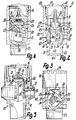
- the device 1 is used to control the pump 2 emitted water flow.
- the pump 2 has a housing 3 to limit a lying pump chamber 4 in which a pump rotor 5 about a horizontal axis like a Centrifugal pump is rotatably mounted. With this runner 5 will through an inlet 6 water into the suction area of the chamber 4 sucked in, conveyed by the rotor 5 in its pressure range and from there via an outlet 7 upwards under positive pressure submitted.
- the axis 4 parallel to the chamber, but eccentric Input 6 is used to connect one end of a flexible Hose and is in the upper area of chamber 4 above the rotor axis.
- the axis of the input 6 is at right angles transverse to the vertical axis of the exit 7.
- the entrance 6 lies in front of the free end face of the rotor 5 and the output 7 between the ends of the rotor 5 adjacent to it Extent and at the top.
- the horizontal axis 14 is coaxial to the rotor axis and on the motor shaft Rotor 5 is arranged immediately rotatably.
- the housing of the Motor 8, on the front side of the housing 3 directly attached, has a laterally protruding on the underside Base plate, which has a flat, footprint 9 parallel to axis 14 as the deepest area of the Motor pump forms.
- the pump 3 is completely above the Stand level 9. At the top is the motor pump, in particular only the motor housing, with a bow-shaped, to the axis 14 parallel carrying handle 11 provided.
- the electric motor 8 is via a connection cable led out of its housing the power grid can be connected.
- On the outside of the engine case is a switch for manual switching on and off accessible to the motor pump.
- the pump 2 is non-destructive removable, as it is firmly connected to the motor housing Housing 3 can be solved.
- the housing 3 has an axis 14 parallel process 12, which in the lowest area to the Chamber 4 connected and with a screw cap or the like. is closable so that after opening the chamber 4 completely can be emptied.
- the case shows in the upper area 3 above the entrance 6 one with a screw cap or The like.
- Lockable filling opening at right angles to the axis 14 13 through which the chamber, the entrance 6 and the this suction line connecting to the outside before commissioning the pump 2 are completely filled with water can, since the opening 13 at least as high as the exit 7 lies.
- the opening 13 opens directly with the vertical axis in the entrance 6 or in the transition area between chamber 4 and entrance 6.
- the device 1 has a preassembled unit 15 non-destructive detachable attachment to the top of the Housing 3 between the motor 8 and the handle 11 and the Openings 6, 13.
- the housing 3 forms in this area in the axis 10 of the output 7 a flange 16 for receiving the unit 15, which in turn is a continuation of the exit 7 delimits a flow channel 17 over its circumference.
- unit 15 forms its entrance and at the top End of their exit, at which a water pipe leading away, for example a non-destructive flexible hose can be detachably connected.
- the unit 15 has an exposed, tubular housing 2, which consists of only two axes adjoining housing parts 18, 19 assembled is.
- One housing part 18 forms the exit 7 Input of the unit 15 and the other housing part 19 the Connection coupling for the outgoing line.
- the housing part 19 engages over a partial length of the housing part 18 in the latter Inside and is in this area with an external thread into an internal thread in the outer jacket of the housing part 18 screwed in sealed.
- a control valve 22 is provided at the inlet end.
- the housing part 18 forms an im Diameter reduced nozzle 23 for immediate and clamped connection with the flange 16, in which the Spigot 23 as one piece with the rest of the housing part 18th trained connecting part protrudes.
- the unit 15 can compared to the housing 3 about the axis 10 or the like Setting rotatably mounted or in relation to the housing 3 be tightly clamped.
- the valve 21 has a valve body 24 that opposes Flow direction to exit 7 in the closed position and in Flow direction away from exit 7 in the open position opposite an annular, planar valve seat 25 in parallel is movably mounted to the axis 10 on the housing 20. Upstream is directly adjacent to the valve body 24 Valve body 26 of the valve 22 on the housing 20 or only on Housing part 18 in different functional positions movably mounted, with its outer surface permanently under Bias from a valve seat 27 is present.
- the valve seat 25 points in the direction of flow and the valve seat 27 in opposite direction against flow direction.
- valve seats 25, 26 are coaxial to each other in the Axis 10.
- the valve seat 25 is dimensionally stable and the valve seat 27 pressure elastic. That of the valve seat 25 during the opening movement lifting closing surface of the valve body 24 is by an annular, on the outer circumference of the valve body 24, annular seal 28 arranged in an annular groove educated.
- the closing surface 27 of the valve 22 is by a annular or sleeve-like, like the seal 28 pressure-elastic Seal 29 formed on which the valve body 26th with a dimensionally stable circumferential surface.
- the two seats 25, 27 are on a common, one-piece and sleeve-shaped Valve insert 30 is provided in a fixed position, the opposite Direction of flow guided in the housing part without radial play 18 used and with the housing part 19 against the circumference of the Valve body 26 is clamped axially so that the valve body 26 despite the friction on the seat 27 smooth enough can be rotated.
- the insert 30 forms a tubular, downstream one End and as an upstream end an annular Front wall that only over the inner circumference of the sleeve end protrudes, forms the seat 25 with its inner end face and the seal 29 in a groove on its outer end face with the seat 27 so that the valve body 26 in the Intervenes inside this end wall.
- Another insert 31 lies at the end of the insert 30 with an outermost ring section between your Housing part 19 and the insert 30 is so that it with the Housing part 19 is clamped axially against the insert 30 and this in turn clamps against the valve body 26.
- the insert 31 forms a guide in the center for the central, freely projecting shaft of the Valve body 24, the guide bushing with the outer ring Is rigidly connected via webs, which about the axis 10 are distributed.
- a compression spring or coil spring as valve spring 32 arranged with one end on the guide bush and with the other end directly on the one-piece with the shaft trained valve body 24 is supported.
- the spherical valve body 26 is from a bore or a passage 33 limited only on the outer circumference, which is a continuation of the flow channel 17 according to FIG. 2 can form, only slightly narrower than the subsequent ones Portions of the channel formed by the housing 20 is one the body 26 carrying shaft 34 penetrates, as shown in FIG. 2 in the axis 10 lies and on one opposite its side shorter length at the outlet end tapers conically is.
- the shaft 34 passes through the body 26 in the middle the ends of the passage 33 and is non-rotatable opposite openings of the casing of the housing part 18, which passes through, rotatable and axially secured stored.
- the axis of rotation 35 of the body 26, 34 intersects the Axis 10 at right angles across and passes through the passage 33 because this also penetrates the shaft 34 at a constant width.
- one Handle 42 On one end of the shaft 34 on which the body 26 axially self-aligning can be arranged is one Handle 42, for example a rotary knob, fixed against rotation, while at the other end a non-destructively removable Axial abutment is attached, which on one of the Handle 42 facing away from the shoulder surface of the housing part 18 is axially supported and after removal, pulling out the Shaft 34 together with the outside handle 42 the housing part 18 and the body 26 allowed.
- one Handle 42 for example a rotary knob, fixed against rotation, while at the other end a non-destructively removable Axial abutment is attached, which on one of the Handle 42 facing away from the shoulder surface of the housing part 18 is axially supported and after removal, pulling out the Shaft 34 together with the outside handle 42 the housing part 18 and the body 26 allowed.
- the housing part 19 When mounting is from the side of the engagement of the housing part 19 ago first the body 26 axially, then the shaft 34 radially, then the body 30 axially, then further the pre-assembled unit from the bodies 24, 28, 31, 32 axially and finally the housing part 19 is inserted axially and tense. Thereafter, the unit 15 can be attached to the flange 16 be attached.
- the housing part 18 could also be first Flange 16 are attached and then the assembly mentioned of components 26, 34, 30, 24, 32, 31, 19 in this order respectively.
- the body 26 can instead of the valve function or in addition a control body 36 for direct actuation of the Form valve body 24.
- a control curve 37, 38 on which sunk against the ball or outer circumference lies and through the bottom of an obtuse V-shaped limited groove is formed.
- the curve has two on either side of the passage 33 opposite each other, different long curve sections, of which the longer one Section 37 with both ends to one end of the Passage 33 extends and extends over an arc angle of Extends 90 °.
- the end of the valve 31 shown in FIG. 2 is spiral curve 37 curved around axis 35 has its smallest Distance from the axis 35, so that here the cam groove is the deepest. Opposing this end is essential Steeper curve section 38 is provided, which is over an arc angle of less than 30 ° around axis 35 extends, but also with one end to the circumference of the ball connects and with the other end its smallest distance of the axis 35, which is approximately equal to the corresponding one Distance of section 37 is.
- the curve groove penetrates hence the narrowed portion of the passage 33 at two opposite sides over its entire length.
- the valve body 24 For the engagement in the control curve 37, 38, the valve body 24 a cam 39 directed against the axis 35, which is formed in one piece with the body 24 and by its directed by the seal 28 against the control body 36 rounded cone tip is formed. Together the sections 37, 38 extend over an arc angle of 180 °.
- the arc angles mentioned can be maximum or Represent minimum values, each at least by 10, 20 or 30 ° can deviate.
- the larger radial distance of the Control curve 37, 38 corresponds to the ball radius, so that the Ball circumference in continuation of the slope sections 37, 38 Forms curve sections with constant radial distance.
- the groove 37, 38 guides the body 24 against the cam 39 against the side Axis 35 parallel movements positively.
- the seat 27 crosses the Curve groove 37 between its ends, so that on the outer circumference of the body 26, the two flow sides of the seat 27 connecting passage cross section results, which by a Is many times smaller than that of the passage 33.
- this passage cross section can be changed continuously to zero.
- the passage 33 limits a steplessly simultaneously with the seat 27 variable flow cross-section so that the flow rate by the unit 15 with the same drive power of the pump 2 or the motor 8 can be changed as desired.
- Of the Body 26 is here in the passage 33 and on the outer circumference by the water flowing past the valves 21, 22 flows around.
- the passage cross section at most is five, two or a square millimeter.
- the inner circumference of the passage 33 with the outer circumference of the body 26 in the circumferential distance from the curve 37, 38 and the ends of the passage 33 connected by a channel 41, which is perpendicular to the axis of the passage 33 Axial plane of axis 35 closer to 2 and only the inlet end of the passage 33 Body 26, but not penetrated the shaft 34.
- Channel 41 is narrowest at the passage 33 and the outer circumference of the Body 26 farthest, with its narrowest diameter at most three or two millimeters, especially one Is millimeters.
- the seat 27 is by the Part of the outer periphery of the body 26 belonging to curve 38 tightly closed, but this can be from the input side Seat 27, namely through the passage 33 and the channel 41, Air flows to and through the open valve 21. Thereby can the water in case it is foamed with air pockets flows to the unit 15, vented, thereby the Suction capacity of pump 2 optimized through input 6 becomes.
- the effective passage cross section of the channel 41 can thereby by more or less strong coverage with the seat 37 can be changed continuously.
- valve 21 In the position shown in FIG. 3, the valve 21 is manual opened and water can flow down from the flow channel flow through the valves 21, 22 into the chamber 4, from where it flows off when the drain 12 is open, as a result of which the input 6 can be emptied with the associated suction line.
- the water both through the passage 33 and along the outer circumference of the body 26 through the conduit 37 flow away.
- FIG. 4 could also be used for the function Fig. 4 can be used because the conduit 37 for ventilation suitable is. However, in the position shown in FIG. 4 Curve 37 on the side facing away from the valve 21, 27 Axis 35, so that the ventilation only through channel 41 he follows. 3, the channel 41 can pass through the backflowing water can be cleaned in countercurrent, if deposits should have built up in it.
- the control means 43 described can be used with a single handle 42 set all functions described.
- a measuring device 44 can also belong to the unit 15, which, for example, the flow rate and / or the pressure of the water flowing through and the corresponding Values via signal lines to an electronic control or Control device 46 forwards, which the pump 2 and the Motor 8 depending on the signals for regulating the Even delivery rate only between the on and off state reversed.
- the housing part 19 forms with a Measuring housing 45 is a one-piece unit that is used for detection the flow rate exposed to the flow in channel 17, turbine-like rotor or rotor and one Contains pressure of the fluid exposed membrane or the like.
- the horizontal axis 47 of the housing 45 is at right angles to axis 10 and laterally opposite this to the switch side of the motor 8 or to the side of the handle 42 to the front offset so that the housing 45 with the housing part 19 a T-shape, of which the housing part 19 forms the T-crosspiece represents.
- the control device above the motor 8 46 pivotable about the axis 47 and self-locking due to friction lockable. This allows the control panel 48 of the control device 46 in different inclination positions be transferred.
- Panel 48 contains displays for the operating state of the pump unit and, if applicable, for the Measured values and a switch for switching the on and off Pump 2.
- the devices 44, 46 can also together around the axis 10 adjusted and so in the most favorable operating position to be brought.
- the housing of the device 46 lies completely separate from the flow paths or from channel 17 the top of the housing 45 so that in the device 46th and the electronic controls it contains no water can penetrate.
- the housing of the Device 46 sunk in a fixed position, carry in which the plug of a connecting cable of the motor 8 is inserted and thereby this into the circuit of an interrupter the device 46 can be interposed.
- a power cord runs from the back of this case away with which this circuit and therefore the motor 8 can be connected to the mains.
- the handle 42 is on Outer periphery of the housing part 18 rotatable about the axis 10 stored.
- the curve 37 is immediately outside the housing 20 provided on the handle 42 and acts on one Cam 39, which is fixed with the axially displaceable Body 30 is connected and to secure it against rotation penetrates a slot in part 18.
- Drainage position. 5 are the inflow and Outflow side of the valve only via the bypass 41 with each other wired, which the jacket 30 immediately penetrated adjacent to the seat 25, between two ring seals lies and works as a slide valve 22.
- This bypass 41 connects the inner circumference of the body 30 to its outer circumference and is tightly closed in the other positions.
Landscapes
- Mechanically-Actuated Valves (AREA)
- Control Of Non-Electrical Variables (AREA)
- Lubricants (AREA)
- Details Of Reciprocating Pumps (AREA)
Applications Claiming Priority (2)
| Application Number | Priority Date | Filing Date | Title |
|---|---|---|---|
| DE19629137 | 1996-07-19 | ||
| DE19629137A DE19629137A1 (de) | 1996-07-19 | 1996-07-19 | Steuereinrichtung für ein Fluid, wie Wasser |
Publications (3)
| Publication Number | Publication Date |
|---|---|
| EP0819474A2 true EP0819474A2 (fr) | 1998-01-21 |
| EP0819474A3 EP0819474A3 (fr) | 1999-03-03 |
| EP0819474B1 EP0819474B1 (fr) | 2007-02-07 |
Family
ID=7800262
Family Applications (1)
| Application Number | Title | Priority Date | Filing Date |
|---|---|---|---|
| EP97112016A Expired - Lifetime EP0819474B1 (fr) | 1996-07-19 | 1997-07-15 | Dispositif de commande pour un fluide tel que de l'eau |
Country Status (3)
| Country | Link |
|---|---|
| EP (1) | EP0819474B1 (fr) |
| AT (1) | ATE353252T1 (fr) |
| DE (2) | DE19629137A1 (fr) |
Cited By (7)
| Publication number | Priority date | Publication date | Assignee | Title |
|---|---|---|---|---|
| EP0992687A3 (fr) * | 1998-10-07 | 2001-01-31 | GARDENA Kress + Kastner GmbH | Régulation du débit d'une pompe ménagère avec une soupape |
| EP0992686A3 (fr) * | 1998-10-07 | 2001-03-07 | GARDENA Kress + Kastner GmbH | Régulation du débit d'une pompe ménagère avec une soupape |
| WO2001018441A1 (fr) * | 1999-09-03 | 2001-03-15 | Oase Wübker GmbH & Co. KG | Raccord de tuyau de refoulement pour pompe |
| EP4410436A1 (fr) * | 2023-01-31 | 2024-08-07 | W.M. Barr & Company, Inc. | Lance de pulvérisation |
| US12103025B2 (en) | 2019-12-20 | 2024-10-01 | W.M. Barr & Company, Inc. | Spray wand |
| US12263508B2 (en) | 2019-12-20 | 2025-04-01 | W.M. Barr & Company, Inc. | Spray wand |
| US12485438B2 (en) | 2019-12-20 | 2025-12-02 | W.M. Barr & Company, Inc. | Spray wand |
Families Citing this family (3)
| Publication number | Priority date | Publication date | Assignee | Title |
|---|---|---|---|---|
| DE19923357A1 (de) * | 1998-10-07 | 2000-04-13 | Gardena Kress & Kastner Gmbh | Flüssigkeitspumpenanordnung, insbesondere für die Verwendung in Haus und/oder Garten |
| DE10062207B4 (de) * | 2000-12-13 | 2011-07-21 | ITT Manufacturing Enterprises, Inc., Del. | Pumpe mit wählbaren Ansaugöffnungen |
| DE102005045861A1 (de) * | 2005-09-21 | 2007-03-29 | Gardena Manufacturing Gmbh | Einrichtung zur Fluidsteuerung, Gehäusebauteil mit einer derartigen Einrichtung und damit ausgestattete Pumpeinrichtung |
Family Cites Families (13)
| Publication number | Priority date | Publication date | Assignee | Title |
|---|---|---|---|---|
| US2399300A (en) * | 1941-08-29 | 1946-04-30 | Crown Cork & Seal Co | Filling apparatus and valve |
| US2641437A (en) * | 1948-05-03 | 1953-06-09 | Jay Carl | Check valve with supplemental cam actuator |
| DE1128711B (de) * | 1957-03-28 | 1962-04-26 | Kloeckner Humboldt Deutz Ag | Steuervorrichtung fuer ein hydraulisches System |
| US2991800A (en) * | 1957-12-11 | 1961-07-11 | Logansport Machine Company | Air valve |
| US3420493A (en) * | 1965-12-13 | 1969-01-07 | Wilbur P Kraft | Combination metering,check and shut-off valve |
| DE1550249B2 (de) * | 1966-05-26 | 1970-11-19 | Gustav F. Gerdts KG, 28OO Bremen | Entsperreinrichtung für Rückschlagventile |
| DE1600844A1 (de) * | 1967-02-23 | 1970-03-19 | Elisabeth Lohoff Geb Krake | Rueckschlagventil |
| AT320440B (de) * | 1972-09-13 | 1975-02-10 | Vortex Pumpen Ag | Kreiselpumpe mit einem den Pumpenläufer tragenden Antriebsmotor |
| US4690169A (en) * | 1986-04-04 | 1987-09-01 | Jogler, Inc. | Combined shut off and check valve |
| US4366834A (en) * | 1980-10-10 | 1983-01-04 | Sargent-Welch Scientific Company | Back-flow prevention valve |
| US4580596A (en) * | 1983-01-18 | 1986-04-08 | Stehling Henry J | Check valve with dual locking mechanism |
| US5190074A (en) * | 1992-04-20 | 1993-03-02 | Christopher Gilman O | Check valve apparatus |
| US5509787A (en) * | 1994-10-07 | 1996-04-23 | Valdes; Osvaldo J. | Hydraulic actuator for pressure switch of fluidic system |
-
1996
- 1996-07-19 DE DE19629137A patent/DE19629137A1/de not_active Withdrawn
-
1997
- 1997-07-15 DE DE59712808T patent/DE59712808D1/de not_active Expired - Lifetime
- 1997-07-15 AT AT97112016T patent/ATE353252T1/de not_active IP Right Cessation
- 1997-07-15 EP EP97112016A patent/EP0819474B1/fr not_active Expired - Lifetime
Non-Patent Citations (1)
| Title |
|---|
| None |
Cited By (7)
| Publication number | Priority date | Publication date | Assignee | Title |
|---|---|---|---|---|
| EP0992687A3 (fr) * | 1998-10-07 | 2001-01-31 | GARDENA Kress + Kastner GmbH | Régulation du débit d'une pompe ménagère avec une soupape |
| EP0992686A3 (fr) * | 1998-10-07 | 2001-03-07 | GARDENA Kress + Kastner GmbH | Régulation du débit d'une pompe ménagère avec une soupape |
| WO2001018441A1 (fr) * | 1999-09-03 | 2001-03-15 | Oase Wübker GmbH & Co. KG | Raccord de tuyau de refoulement pour pompe |
| US12103025B2 (en) | 2019-12-20 | 2024-10-01 | W.M. Barr & Company, Inc. | Spray wand |
| US12263508B2 (en) | 2019-12-20 | 2025-04-01 | W.M. Barr & Company, Inc. | Spray wand |
| US12485438B2 (en) | 2019-12-20 | 2025-12-02 | W.M. Barr & Company, Inc. | Spray wand |
| EP4410436A1 (fr) * | 2023-01-31 | 2024-08-07 | W.M. Barr & Company, Inc. | Lance de pulvérisation |
Also Published As
| Publication number | Publication date |
|---|---|
| ATE353252T1 (de) | 2007-02-15 |
| EP0819474B1 (fr) | 2007-02-07 |
| DE19629137A1 (de) | 1998-01-22 |
| DE59712808D1 (de) | 2007-03-22 |
| EP0819474A3 (fr) | 1999-03-03 |
Similar Documents
| Publication | Publication Date | Title |
|---|---|---|
| DE3049613C2 (fr) | ||
| EP0826426B1 (fr) | Arroseur | |
| DE2359312C3 (de) | Mischventil | |
| EP0043076B1 (fr) | Robinet mélangeur pour liquides | |
| DE4422749A1 (de) | Pumpenschutzventil | |
| DE4024726A1 (de) | Membranventil | |
| EP0819474B1 (fr) | Dispositif de commande pour un fluide tel que de l'eau | |
| DE3110151C2 (de) | Vorrichtung zum Betätigen eines heb- und senkbaren Ventilkegels eines Wannenablaufventils | |
| EP0112977A1 (fr) | Organe d'arrêt pour fluides agressifs | |
| EP0410198B1 (fr) | Arroseur escamotable | |
| DE3509720C2 (fr) | ||
| DE10232506A1 (de) | Zapfhahn für Getränke mit einem Drehschieber | |
| DE3038007C2 (de) | Mischventil | |
| DE2907565C2 (de) | Kombinierte Selbstschluß- und Mischarmatur | |
| DE3309339A1 (de) | Mischbatterie | |
| DE3149116C2 (de) | Ventil zur Probeentnahme von flüssigen Medien | |
| DE4318837A1 (de) | Vorrichtung zum Auslösen und Unterbrechen des Wasserlaufs aus einer Wasseraustrittsöffnung | |
| EP1234917A1 (fr) | Robinetterie sanitaire | |
| DE69820875T2 (de) | Durchflussbegrenzer | |
| DE3833177C2 (fr) | ||
| DE8607840U1 (de) | Einhand-Kupplung mit Sitzventil, für Schläuche und/oder Rohre | |
| DE3041696A1 (de) | Mischbatterie | |
| DE8909346U1 (de) | Wasserhahn | |
| DE9204975U1 (de) | Mehrwegeventil für einen Badewannenlift | |
| DE2633548A1 (de) | Hebelmischventil |
Legal Events
| Date | Code | Title | Description |
|---|---|---|---|
| PUAI | Public reference made under article 153(3) epc to a published international application that has entered the european phase |
Free format text: ORIGINAL CODE: 0009012 |
|
| AK | Designated contracting states |
Kind code of ref document: A2 Designated state(s): AT DE FR IT |
|
| PUAL | Search report despatched |
Free format text: ORIGINAL CODE: 0009013 |
|
| AK | Designated contracting states |
Kind code of ref document: A3 Designated state(s): AT BE CH DE DK ES FI FR GB GR IE IT LI LU MC NL PT SE |
|
| 17P | Request for examination filed |
Effective date: 19990825 |
|
| AKX | Designation fees paid |
Free format text: AT DE FR IT |
|
| 17Q | First examination report despatched |
Effective date: 20010529 |
|
| RAP1 | Party data changed (applicant data changed or rights of an application transferred) |
Owner name: GARDENA MANUFACTURING GMBH |
|
| GRAP | Despatch of communication of intention to grant a patent |
Free format text: ORIGINAL CODE: EPIDOSNIGR1 |
|
| GRAS | Grant fee paid |
Free format text: ORIGINAL CODE: EPIDOSNIGR3 |
|
| GRAA | (expected) grant |
Free format text: ORIGINAL CODE: 0009210 |
|
| AK | Designated contracting states |
Kind code of ref document: B1 Designated state(s): AT DE FR IT |
|
| RIN1 | Information on inventor provided before grant (corrected) |
Inventor name: DIE ERFINDER HABEN AUF IHRE NENNUNG VERZICHTET. |
|
| REF | Corresponds to: |
Ref document number: 59712808 Country of ref document: DE Date of ref document: 20070322 Kind code of ref document: P |
|
| ET | Fr: translation filed | ||
| PLBE | No opposition filed within time limit |
Free format text: ORIGINAL CODE: 0009261 |
|
| STAA | Information on the status of an ep patent application or granted ep patent |
Free format text: STATUS: NO OPPOSITION FILED WITHIN TIME LIMIT |
|
| 26N | No opposition filed |
Effective date: 20071108 |
|
| PG25 | Lapsed in a contracting state [announced via postgrant information from national office to epo] |
Ref country code: IT Free format text: LAPSE BECAUSE OF FAILURE TO SUBMIT A TRANSLATION OF THE DESCRIPTION OR TO PAY THE FEE WITHIN THE PRESCRIBED TIME-LIMIT Effective date: 20070207 |
|
| PGFP | Annual fee paid to national office [announced via postgrant information from national office to epo] |
Ref country code: AT Payment date: 20080722 Year of fee payment: 12 |
|
| PG25 | Lapsed in a contracting state [announced via postgrant information from national office to epo] |
Ref country code: AT Free format text: LAPSE BECAUSE OF NON-PAYMENT OF DUE FEES Effective date: 20090715 |
|
| REG | Reference to a national code |
Ref country code: FR Ref legal event code: TP Owner name: HUSQVARNA AB, SE Effective date: 20140407 |
|
| REG | Reference to a national code |
Ref country code: DE Ref legal event code: R081 Ref document number: 59712808 Country of ref document: DE Owner name: HUSQVARNA AB, SE Free format text: FORMER OWNER: GARDENA MANUFACTURING GMBH, 89079 ULM, DE Effective date: 20140627 |
|
| REG | Reference to a national code |
Ref country code: FR Ref legal event code: PLFP Year of fee payment: 20 |
|
| PGFP | Annual fee paid to national office [announced via postgrant information from national office to epo] |
Ref country code: FR Payment date: 20160626 Year of fee payment: 20 |
|
| PGFP | Annual fee paid to national office [announced via postgrant information from national office to epo] |
Ref country code: DE Payment date: 20160512 Year of fee payment: 20 |
|
| REG | Reference to a national code |
Ref country code: DE Ref legal event code: R071 Ref document number: 59712808 Country of ref document: DE |